patent · US3878410
Two-phase liquid-metal magnetohydrodynamic (MHD) generator
15 April 1975
Page 1 — bibliographic record
United States Patent (19) (1) 3,878,410 Petrick et al. (45) Apr. 15, 1975
(54) TWO-PHASE LIQUID-METAL 3,309,545 3/1967 Finmerich............................. 310/11 MAGNETOHYDRODYNAMIC (MHD) 3,335,289 8/1967 Kidwell............................. 310/11 X 3,44,744 l2/1968 Petrick.................................. 310/11
GENERATOR 3,525,886 8/1970 Radebold.............................. 310/11 75) Inventors: Michael Petrick, Joliet; John C. 3,634,067 l/1972 Klein................................. 310|| 1 | X Cutting, Downers Grove; William E.
It is is toger L. Cole,
Riverside, all of Ill.
Primary Examiner-Donovan F. Duggan
Attorney, Agent, or Firm-Dean E. Carlson; Arthur A.
(73) Assignee: The United States of America as Churm; Frank H. Jackson represented by the United States -
Energy Research and Development
Administration, Washington, D.C. 57 ABSTRACT 22 Filed: Feb. 21, 1974 Dissipative boundary layer electrical shunts are elimi nated in a two-phase liquid-metal magnetohy 21 Appl. No.: 444,601 drodynamic (MHD) generator by displacing the slow moving, conducting liquid boundary layer adjacent the 52) U.S. Cl. .................................................. 310/11 insulating walls of the generator with a thin gas layer. 51 int. Cl. ........................................... H02k 45/00 This is accomplished by injecting an inert gas into the 58) Field of Search............ 3 10/11, 10; 73/194 FM, generator channel in the direction of flow of the work 417/50 ing fluid through the insulating walls at several loca tions through a narrow slit extending across the insu 56) References Cited lating walls.
UNITED STATES PATENTS
3,274,407 9/1966 Brogan.................................. 310/11 6 Claims, 8 Drawing Figures
Page 2
Drawing sheet — no readable text.
Page 3
Drawing sheet — no readable text.
Page 4
Drawing sheet — no readable text.
Page 5
Drawing sheet — no readable text.
Page 6
TWO-PHASE LIQUID-METAL a boundary-layer resistance of 0.25 to 0.50 milliohms MAGNETOHYDRODYNAMIC (MHD) is assumed.
GENERATOR
SUMMARY OF THE INVENTION
CONTRACTUAL ORIGIN OF THE INVENTION According to the present invention, improved per The invention described herein was made in the formance of a two-phase liquid-metal MHD generator course of, or under, a contract with the UNITED is attained by eliminating dissipative boundary-layer STATES ATOMIC ENERGY COMMISSION electrical shunts. This is accomplished by displacing
BACKGROUND OF THE INVENTION
the slow-moving conducting-liquid boundary layer ad () jacent the insulating walls of the generator with a thin
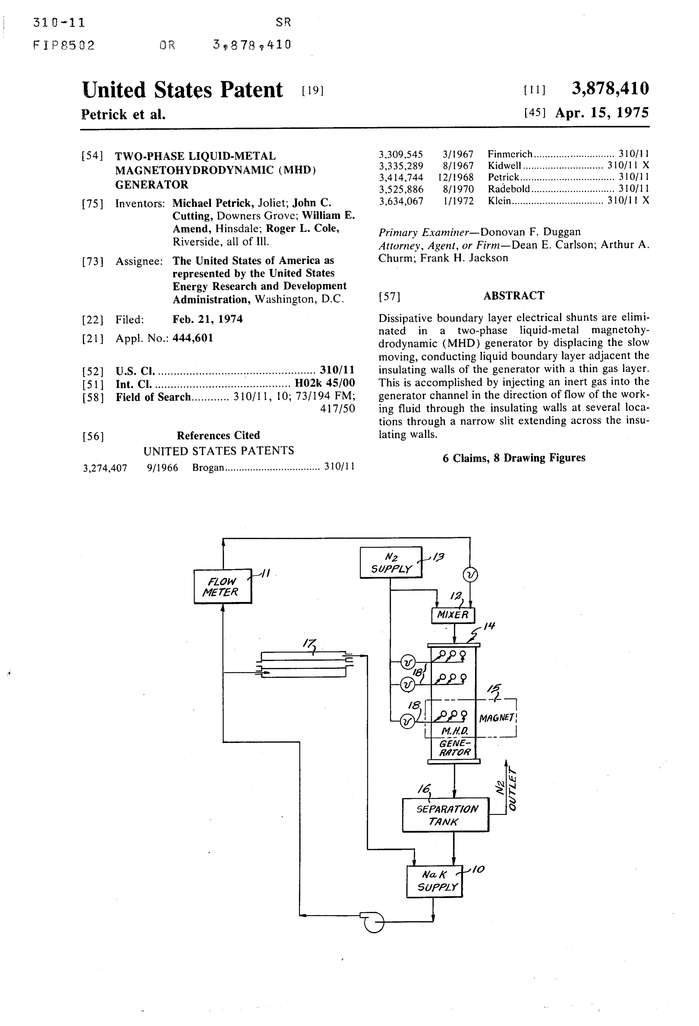
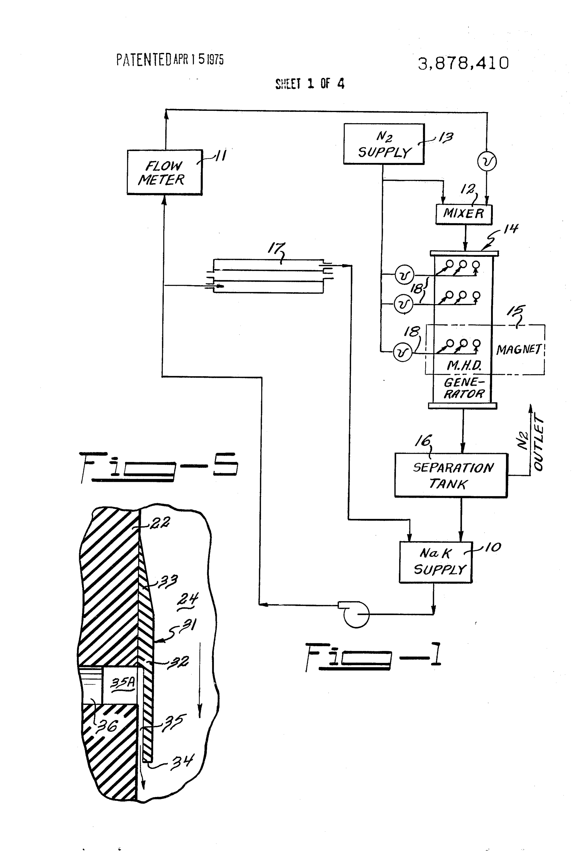
This invention relates to an apparatus for converting gas layer (0.0305 cm thick). An inert gas is introduced thermal energy to electrical energy. In more detail, the into the generator channel through the insulating walls invention relates to an apparatus for generating elec at a number of locations in the direction of flow of the tricity employing a two phase fluid consisting of a dis working fluid through a narrow slit or slits extending persion of an inert gas in an electrically conductive liq 5 across the insulating walls from electrode to electrode. uid as working fluid in a generator. In still more detail, DESCRIPTION OF THE FIGURES the invention relates to a two-phase liquid-metal mag netohydrodynamic (MHD) generator in which dissipa The invention will next be described in connection tive boundary layer electrical shunts have been elimi with the accompanying drawing wherein: nated. 20 FIG. l is a flow diagram of an ambient temperature Research performed at Argonne National Labora installation incorporating a MHD generator according tory over the last decade has shown that liquid-metal to the present invention;
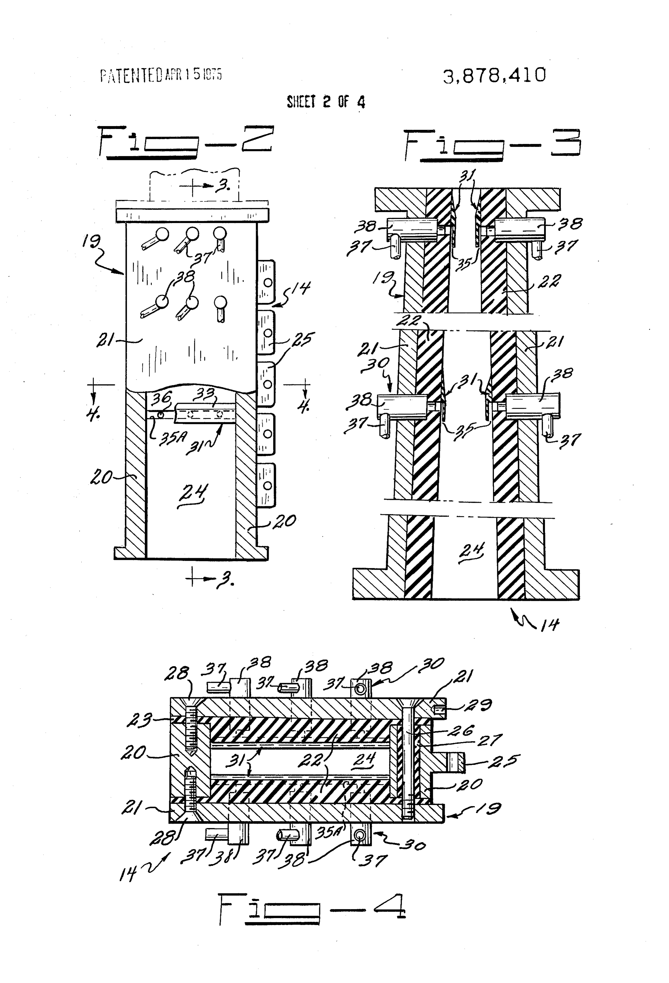
power systems offer significant potential advantages FIG. 2 is a vertical cross section taken through the over conventional energy conversion systems. These 2 5 MHD generator;
potential advantages include relatively high cycle effi FIG. 3 is a vertical cross section taken in the direc ciencies, increased reliability of operation at higher tion of the arrows 3-3 in FIG. 2;
temperatures, and reductions in power system volumes FIG. 4 is a horizontal section taken in the direction and weights. System studies have indicated the cycle of the arrows 4-4 in FIG. 2:
efficiency of power-generating plants using two-phase FIG. 5 is a detail view of a nozzle used for gas injec liquid-metal generators could be 50 percent or more. 30 tion.
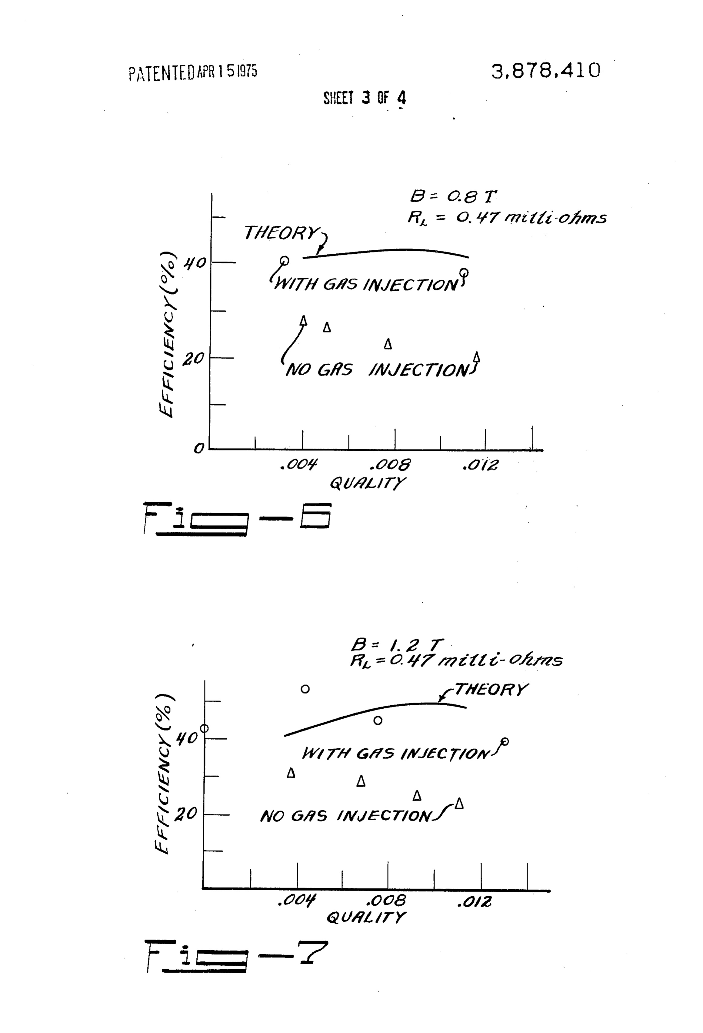
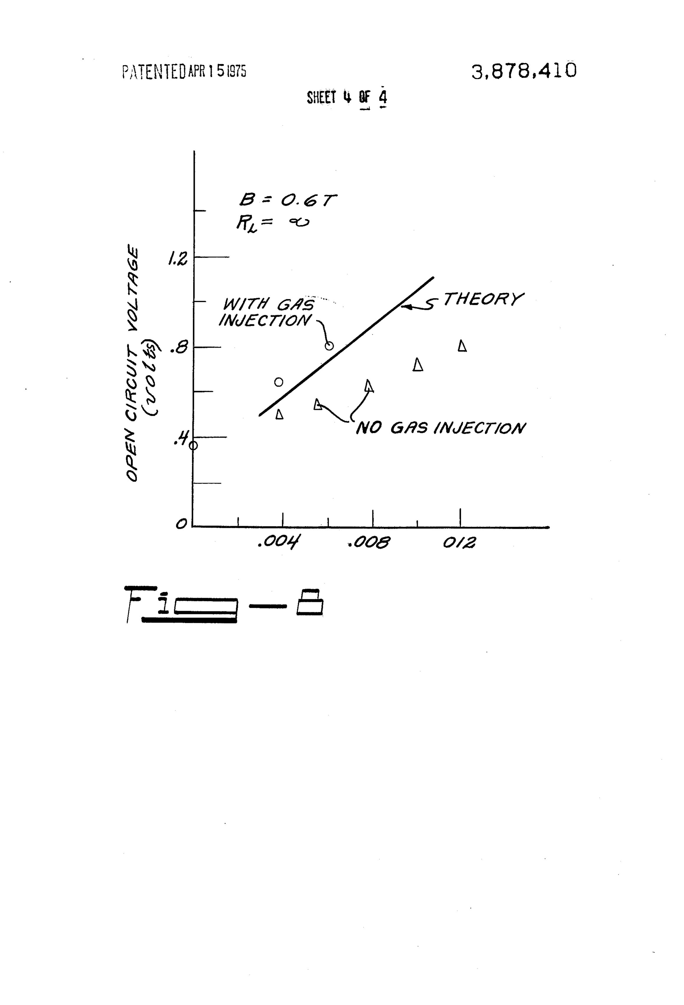
This over-all performance requires an MHD turbine ef FIGS. 6 and 7 are graphs comparing measured tur ficiency for the generator of 70 percent at high mixture bine efficiencies as a function of quality for a generator qualities (~0.01). The quality of a mixture of liquid with gas injection with a generator without gas injec and gas is defined as the ratio of the mass flow rate of tion; and gas to the total flow rate. Measurements to date in an FIG. 8 is a graph giving typical open circuit voltage installation operating at or near ambient temperatures vs. quality data for generators with and without gas in with a mixture of NaK (the eutectic of sodium and po jection.
tassium) and nitrogen as working fluid have indicated DESCRIPTION OF THE PREFERRED a significant decrease in generator performance as the 40 EMBODIMENT quality increases beyond 0.002. Thus the object of the present invention is to develop a two-phase liquid Referring first to FIG. I., NaK is pumped from supply metal MHD generator having better performance at tank 10 through flowmeter 11 to mixer 12 where it is higher mixture qualities. mixed with a metered amount of nitrogen from nitro Experimental data obtained at Argonne National 45 gen source 13. The resulting two-phase working fluid Laboratory coupled with theoretical analysis and mod flows rapidly through a magnetic field created in MHD eling has shown that an electrical shunt existed in the generator 14 by magnet 15 to generate electricity generator as originally designed, causing the above therein and discharges into separation tank 16. Here noted decrease in generator performance at higher the nitrogen is exhausted to the atmosphere and the mixture quality. A portion of the electrical shunt was 50 NaK is returned to supply tank 10. A portion of the removed by redesigning and rebuilding the generator to NaK pumped from the supply tank is cycled through completely eliminate leaks of working fluid and thus a heat exchanger 17 for cooling and return to the storage short behind the insulating side walls and a gas-cleaning tank. In accordance with this invention and as will next system and a micropore NaK filter was installed to min be described, nitrogen is fed to MHD generator 14 at imize the amount of gas impurities that could enter the 55 three locations on each side of the generator through test facility and remove any oxides as soon as they are lines 18 to eliminate dissipative boundary-layer electri formed. Performance tests indicated some improve cal shunts.
ment in efficiency and performance and hence that a Referring now to FIGS. 2, 3, 4 and 5, MHD generator portion of the electrical shunt was removed. It was evi 14 includes a duct 19 consisting of opposed, parallel dent, however, that the principal electrical shunt still 60 copper electrode walls 20, opposed diverging copper remained. side walls 21, and insulating walls 22 formed of fiber We have determined that a major cause of the lack glass covering the interior of side walls 21, said insulat of performance is the presence of an internal bound ing walls 22 including lips 23 which insulate electrode ary-layer shunt. The basic indications are: walls 20 from side walls 21. In operation, duct 19 is dis 1. Boundary layer calculations based on an integral 65 posed so as to define a vertically disposed channel 24 momentum technique predict a boundary-layer shunt extending therethrough.
resistance between 0.5 and 1.5 milliohms. 2. Good One of the electrode walls 20 is provided with five agreement between experiment and theory exists when lugs 25 for making an electrical connection and this
Page 7
electrode wall, lips 23 of insulating walls 22 and side for plate 32. Changing from a blunt leading edge to a walls 21 are fastened together by bolt 26 which is insu leading edge having a 10' taper gave very slightly im lated from electrode walls 20 by bushing 27. The other proved results, changing from a tapered to a blunt trail electrode wall 20, lips 23 of insulating walls 22 and side ing edge improved results substantially since the flow walls 21 are fastened together by brass bolts 28 which of liquid metal past the tapered trailing edge disrupted are set in silver-bearing paste to assure a good electrical to some extent the flow of gas along the insulating walls connection between the side walls and this electrode. of the duct.
The second electrical connection is to wires set in holes Experimental results obtained to date on an installa 29 in side wall 21 at the same end of the generator as tion similar to that shown in the drawing but incorpo the lugs 25, the wires being held in place by set screws 10 rating parallel side walls rather than diverging side (not shown). Magnet 15 (shown in FIG. 1 only) creates walls indicate that gas injection along the insulating a magnetic field through channel 24, the side walls 21 side walls of a generator has been effective in reducing acting as compensating bars to eliminate the armature the boundary-layer shunt observed in previous experi reaction. Magnet 15 is of an adjustable split-yoke type. ments. Dimensions of the channel were: Length 38.7 The field intensity is continuously adjustable from 0.05 15 cm, breadth 10.2 cm and width l.27 cm. to 1.75 Tesla by varying the power supply output from Void fraction measurements made with a gamma-ray 0 to 250 amperes at 70 volts d.c. scanning system indicate that the injected gas stays In a two-phase generator, the inert gas expands as it near the walls of the generator. Measured turbine effi passes through the channel, expending energy to drive ciencies with gas injection vs. mixture quality are pres the liquid metal against drag forces and electromag ented in FIGS. 6 and 7 for magnetic field strengths of netic forces. As the gas expands, the void fraction in 0.8 and 1.2 Tesla and a load resistance of 0.47 milli creases and the channel walls must diverge so that the ohms. Also present in FIGS. 6 and 7 are the theory for cross-sectional area of liquid flow remains constant, these conditions and previous constant-area channel giving a constant liquid velocity. Thus, as shown in FIG. data taken with no gas injection. The improvement in 3, according to the preferred embodiment of the inven performance with gas injection is about 100% at high tion, insulating walls 22 diverge from top to bottom of qualities (> 0.01) and between 50 and 70% at low the generator. qualities ( ~ 0.04). Good agreement between theory According to the present invention, dissipative boun and experiment is also indicated.
dary layer electrical shunts caused by a slow-moving 30 Typical open-circuit voltage vs. quality data are layer of liquid next to the insulating walls of the genera shown in FIG. 8. The improvement in performance tor are eliminated by providing means for displacing with the gas injection is in excess of 50% at high quali the slow-moving, conducting liquid boundary layer ad ties and between 5 and 20% at the low qualities. This jacent the insulating walls. Three pairs of gas injection trend indicates elimination of the current shunt which ports 30 penetrating insulating walls 22 at the genera had most effect on performance at high qualities where tor entrance, and 0.2 and 0.26 meters downstream 35 the ratio of electrical conductivity of the core of the thereof, are provided for this purpose. Each gas injec working fluid to that in the boundary layer was the tion port 30 includes a nozzle 31 formed by a fiberglass smallest.
plate 32 ( 10 cm x 1.90 cm x 0.089 cm) extending The greater-than-theoretical open-circuit voltages across the generator from electrode to electrode having 40 observed with gas injection are due to the decrease in a 10 leading edge 33 attached to insulating wall 22 and generator cross-sectional area, and consequent velocity a blunt trailing edge 34 spaced from the insulating wall increase at the gas injector locations. When compared to form a slit 35 which is 9.52 cm by 0.0305 cm wide to the theory, modified to account for the reduction in for the injection of an inert gas into channel 24 in the area, the measured voltage exceeded 95% of theoreti direction of flow of the working fluid (see FIG. 5). A 45 cal.
channel 35A extends entirely across the insulating It will be appreciated that much higher temperature walls 22 under each plate 32. Each channel 35A is ser than those employed in the tests reported herein are re viced by three 0.32 cm gas inlet passages 36 extending quired for a commerically practicable generator. Ex through insulating walls 22 and terminating at a chan periments are planned on a system operated at 1,000°F. nel 35A. An inert gas is fed to passages 36 from lines 50 using a mixture of sodium and argon as working fluid. 18 through metal tubes 37 and fiberglass inserts 38 set A practical system for the commerical generation of into a hole in side walls 21 and extending into insulating power might be operated, for example, at 1,600°F. em walls 22. There may be a single slit 35 extending across ploying a mixture of lithium and helium as working the insulating walls 22 or a plurality of colinear slits fluid.
The embodiments of the invention in which an exclu
Experiments employing a mixture of NaK and nitro sive property or privilege is claimed are defined as fol gen have been performed over a wide range of experi lows:
mental conditions. Prior to performing these experi 1. A two-phase liquid-metal magnetohydrodynamic ments in order to test the efficiency of boundary-layer generator comprising a duct consisting of opposing displacement by a gas, a mockup of the generator was 60 metal electrode walls, opposing metal side walls and in tested on a water-flow facility. Four configurations of sulating walls covering the interior of the side walls, gas injector nozzles were studied to determine their ef means for admitting a working fluid consisting of a two fectiveness in disrupting the boundary layer. To deter phase mixture of an inert gas and a liquid metal to one mine effectiveness of the injector nozzles, resistance end of the duct, means establishing a magnetic field between two electrodes mounted flush with the wall 65 through said duct, means for collecting the electric cur was studied. The configuration shown in the drawing rent generated by passage of the working fluid through gave the best results. Other configurations tested in the duct, and means for establishing a thin film of gas cluded tapered trailing edges and blunt leading edges on the insulating walls of the duct to displace the slow
Page 8
moving boundary layer of working fluid including a tening together the side walls, insulating walls and said plurality of nozzles which inject gas into the duct in the one of said electrode walls, bolts fastening the other direction of flow of the working fluid in a narrow slit or electrode wall to the insulating walls and the side walls. slits extending across the insulating walls of the duct, said last mentioned bolts being set in silverbearing said nozzles consisting of an insulating plate extending 5 paste to assure a good electrical connection between across the insulating walls of the duct, the leading edge the side walls and this electrode, means for making an of the insulating plate being fixed to the insulating walls electrical connection to a side wall on the same end of and the trailing edge of the plate being spaced from the the generator as the lugs for making an electrical con insulating walls to create said slit. nection, means for admitting a working fluid consisting 2. A generator according to claim 1 wherein said () of a two-phase mixture of an inert gas and a liquid plate has a 10 leading edge and a blunt trailingedge. metal to the top of the duct, means establishing a mag 3. A generator according to claim 2 including a metal netic field through said duct, and means for establish tube leading into a fiberglass insert in the side walls ing a thin film of gas on the insulating walls of the duct having a passage therein communicating with a passage to displace the slow-moving boundary layer of working through the insulating walls opening into a nozzle. fluid, said last mentioned means consisting of three 4. A generator according to claim 3 wherein three pairs of spaced fiberglass plates extending across the pairs of nozzles are provided, each nozzle having three insulating walls of the duct, the leading edge of said gas inlet passages opening thereinto. plates being fixed to the plate, the trailing edge of said 5. A generator according to claim 4 wherein the elec plates being spaced from the insulating walls to create trode walls of the duct are parallel and the side and in a slit extending across the insulating walls, said fiber sulating walls diverge. glass plates having a 10 leading edge and a blunt trail 6. A two-phase liquid-metal magnetohydrodynamic ing edge, said insulating walls having channels extend generator comprising a vertically disposed duct consist ing there across under the fiberglass plates and having ing of opposing, parallel, copper electrode walls, op three gas inlet passages extending through the insulat posing diverging copper side walls and insulating walls ing wall and opening into each channel, a fiberglass in covering the interior of the side walls, said insulating sert disposed in the side walls having a passage therein walls including lips disposed between the electrode communicating with said gas inlet passages and metal walls and the side walls, one of said electrode walls tubes leading into the fiberglass insert and communi being provided with lugs for making an electrical con cating with the passage
therein.
nection, a bolt surrounded by an insulating bushing fas 30
Provenance
- Collection
- Cited prior art
- Original PDF
- patentimages.storage.googleapis.com →
- Filed
- 1974-02-21
- Pages
- 8
- Method
- pdftotext (the PDF's own text layer) + pdftoppm 300dpi page scans
- Source
- Google Patents bibliographic record
- Granted
- 1975-04-15
- Inventors
- Michael Petrick; John C Cutting; William E Amend; Roger L Cole; US Department of Energy
- Transcribed from
- patentimages.storage.googleapis.com →