patent · US4199021
Thermal energy storage apparatus
22 April 1980
Page 1 — bibliographic record
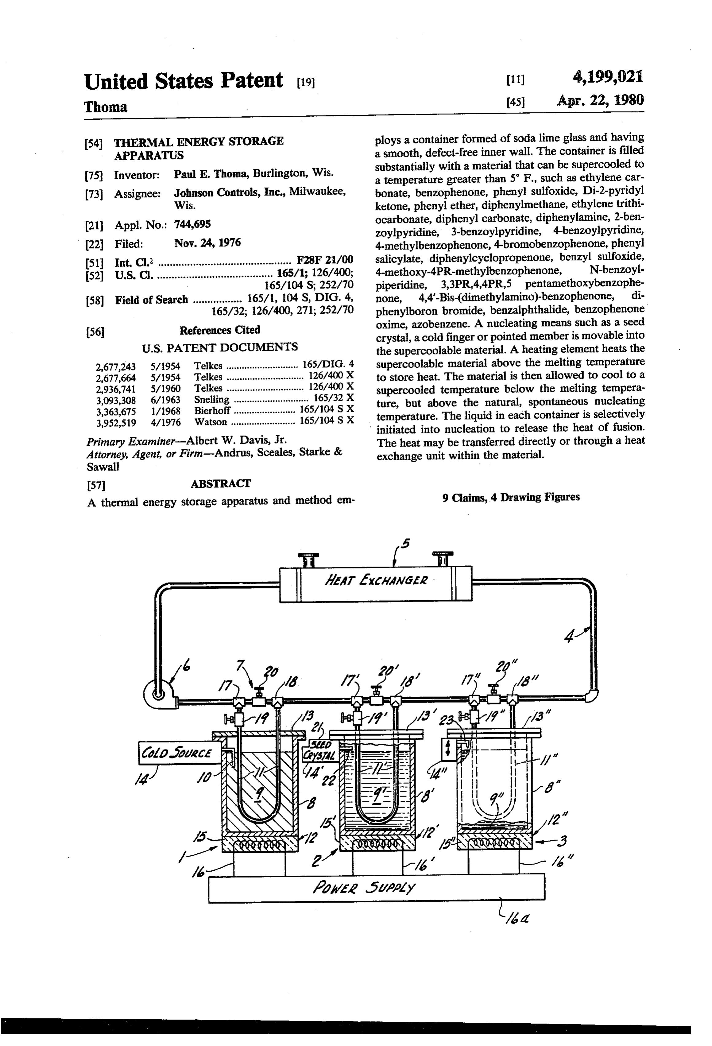
United States Patent (19) 11 4,199,021 Thoma 45 Apr. 22, 1980
54 THERMAL ENERGY STORAGE ploys a container formed of soda lime glass and having APPARATUS a smooth, defect-free inner wall. The container is filled substantially with a material that can be supercooled to 75 Inventor: Paul E. Thoma, Burlington, Wis. a temperature greater than 5 F., such as ethylene car 73) Assignee: Johnson Controls, Inc., Milwaukee, bonate, benzophenone, phenyl sulfoxide, Di-2-pyridyl Wis. ketone, phenyl ether, diphenylmethane, ethylene trithi 21 Appl. No.: 744,695 ocarbonate, diphenyl carbonate, diphenylamine, 2-ben zoylpyridine, 3-benzoylpyridine, 4-benzoylpyridine, 22 Filed: Nov. 24, 1976 4-methylbenzophenone, 4-bromobenzophenone, phenyl 51) Int. C.’.............................................. F28F 21/00 salicylate, diphenylcyclopropenone, benzyl sulfoxide, 52 U.S. C. ........................................ 165/1; 126/400; 4-methoxy-4PR-methylbenzophenone, N-benzoyl 165/104 S; 252/70 piperidine, 3,3PR4,4PR,5 pentamethoxybenzophe 58 Field of Search ................. 165/1, 104 S, DIG. 4, none, 4,4'-Bis-(dimethylamino)-benzophenone, di 165/32; 126/400, 271; 252/70 phenylboron bromide, benzalphthalide, benzophenone 56 References Cited oxime, azobenzene. A nucleating means such as a seed crystal, a cold finger or pointed member is movable into
2,677,243 5/1954 Telkes ............................ 165/DIG. 4 supercoolable material above the melting temperature 2,677,664 5/1954 Telkes .............................. 126/400X to store heat. The material is then allowed to cool to a 2,936,741 5/1960 Telkes. . 126/400X supercooled temperature below the melting tempera 3,093,308 6/1963 Snelling ............................. 165/32 X ture, but above the natural, spontaneous nucleating 3,363,675 l/1968 Bierhoff........................ 165/104 S X temperature. The liquid in each container is selectively 3,952,519 4/1976 Watson ......................... 165/104 SX initiated into nucleation to release the heat of fusion.
Primary Examiner-Albert W. Davis, Jr. The heat may be transferred directly or through a heat Attorney, Agent, or Firm-Andrus, Sceales, Starke & exchange unit within the material. Sawall
A thermal energy storage apparatus and method em 9 Claims, 4 Drawing Figures
AA7 Axaawgaa . |
RNXN
NRN
Page 2
Drawing sheet — no readable text.
Page 3
dia, 3rd Ed., published in 1958 D. Van Nostrand Com
THERMAL ENERGY STORAGE APPARATUS pany, Inc. of New Jersey or McGraw-Hill's Dictionary of Scientific and Technical Terms, Copyright 1974,
BACKGROUND OF THE INVENTION McGraw-Hill Book Company, USA. In the super This invention relates to a thermal energy storage 5 cooled state, the liquid stores thermal energy as the heat apparatus and particularly to an apparatus for storing the storageofover of fusion the supercoolable liquid and will maintain practical periods of indefinite length.
thermal energy in the form of heat of fusion for ex To recover such heat, it is merely necessary to nucleate tended period of storage.
Energy storing systems have been suggested to per 10 the liquid, thereby causing a rapid freezing or solidifica mit storage of the thermal energy from a suitable source tion with a corresponding liberation of the heat stored during low peak usage periods or when such energy is therein. Nucleation is accomplished by any suitable available for subsequent use as necessary. The rather means such as the cold element, seed crystal or sharp serious questions which have recently developed with pointed object.
respect to the availability and cost of natural resources 15 More particularly, the material employed should be in the world have increased the interest in development capable of significant supercooling in the liquid state in of heat storage systems, particularly those which are order to store a significant quantity of thermal energy useful to store solar energy and the like. and is preferably operable at relatively high tempera Although many different thermal storage energy ture such as the environmental temperatures. The melt systems have been suggested, basically three different 20 ing temperature is preferably as high as practical and storage types are available and can be generally classi the natural or spontaneous nucleating temperature fied as (1) liquid storage, (2) solid or packed bed storage, should be as low as practical. and (3) phase change storage. The supercooled liquid in most embodiments must be Liquid storage systems widely employ water as the capable of being selectively initiated into nucleation to thermal energy storage medium. The thermal energy is 25 release the heat of fusion and to release such heat over stored by heating of the liquid and storing it within a a reasonable recovery time period. A supercoolable suitable thermally insulated container. The solid or liquid upon the initial nucleation heats up and, if suffi packed storage system generally operates in a similar cient heat energy is present, rapidly increases to the manner but employs rocks, pebbles and the like which melting temperature. However, the supercooled liquid are heated to store the energy. Phase change energy will not increase above the melting temperature but will storage employs materials which are changed in phase, 30 continue to more slowly solidify and give up the heat of generally to a gaseous state from a liquid state or to a fusion until completely solidified and then will cool to liquid state from a solid state. For example, certain the ambient temperature. The material, the associated systems of the first type employ conversion of water to container steam. Systems of the second type employ conversion 35 cally stableandandnucleating components must be chemi of a sodium salt to a liquid in accordance with the well uncontrolled nucleation ofprevent pure to contamination and the material. The container known equation: Na2SO4.10H2O-Na2SO4+10H2O.
Although such devices have been suggested, the vari preferably also has a smooth interior surface to avoid uncontrolled nucleation and release of the thermal en ous designs generally have certain inefficiencies and ergy.
complexities connected with the storage and recovery Although any supercoolable material can be em of energy. ployed, available materials which have characteristics SUMMARY OF THE PRESENT INVENTION particularly adapted to this present invention include The present invention is particularly directed to an ethylene carbonate, benzophenone, phenyl sulfoxide, Di-2-pyridyl ketone, phenyl ether, diphenylmethane, improved thermal energy storage system employing a ethylene trithiocarbonate, supercooled storage medium in which the energy is nylamine, 2-benzoylpyridine,diphenyl carbonate, diphe
stored as the heat of fusion for an indefinite period of zoylpyridine, 4-methylbenzophenone, 4-bromoben time. Generally in accordance with the present inven zophenone, phenyl salicylate, diphenylcyclopropenone, tion, a supercoolable material is held within a suitale container means. The supercoolable material is selected benzyl sulfoxide, 4-methoxy-4pr-methylbenzophenone, N-benzoylpiperidine, 3,3pr,4,4pr 5 pentamethoxyben to have a supercooled liquid state of at least five degrees zophenone, 4,4'-Bis-(dimethylamino)-benzophenone,
of supercooling below the normal melting temperature. diphenylboron bromide, benzalphthalide, benzophe The material is such that when in the supercooled liquid none oxime, azobenzene and the like with greater than state, solidification or freezing can be initiated by spon 5 F. supercooling. Mixtures of such materials with taneous nucleation or by use of a nucleating device such as a cold element, a seed crystal, or a sharp pointed 55 each other and with other materials which form a eutec object. In the storage of energy, the material is heated to tic composition will also provide supercoolable charac its melting temperature to form a liquid body above the ter. The materials generally operated at elevated tem melting temperature. The liquid body is then allowed to peratures and thus are conveniently stored in natural cool to a temperature below the melting temperature, environments. For example, ethylene carbonate sponta that is to the temperature of the surrounding environ 60 neously solidifies at approximately 45 F., ethylene ment. As the supercoolable liquid cools below the melt trithiocarbonate solidifies at approximately 50 F., and ing temperature, it does not freeze or change state but benzophenone solidifies at a temperature below -20 rather supercools in the liquid state to the temperature F. These materials are available commercially and the of the surroundings. This characteristic is generally ambient storage temperature is readily held above such defined as creating a metastable state of the liquid, with 65 aPhenyl spontaneous solidification temperature for storage.
salicylate similarly functions with a somewhat the reference to the normal same freezing and melting temperature of most liquids. For example, reference longer period of freezing and, therefore, timed release may be made to Van Nostrand's Scientific Encyclope of thermal energy.
Page 4
In a highly practical system, for example, used for nucleating temperature encountered in northern cli heat storage and selective release, 4-benzoylpyridine nates.
may be the supercoolable material. A satisfactory con The present invention provides a relatively simple tainer means is a soda lime glass formed as a suitable and reliable energy storage means and method having a smooth wall container. A suitable nucleating means large capacity for storing of thermal energy for indif such as pointed member, a seed crystal source or a nite periods in combination with a convenient and prac rod-like element coupled to a cooling means is secured tical means of selective recovery of such energy. to the container for entry into the supercoolable mate BRIEF DESCRIPTION OF THE DRAWING rial. A heating unit is incorporated into the assembly, such as a part of the container. A heat transfer conduit 10 In the drawing:
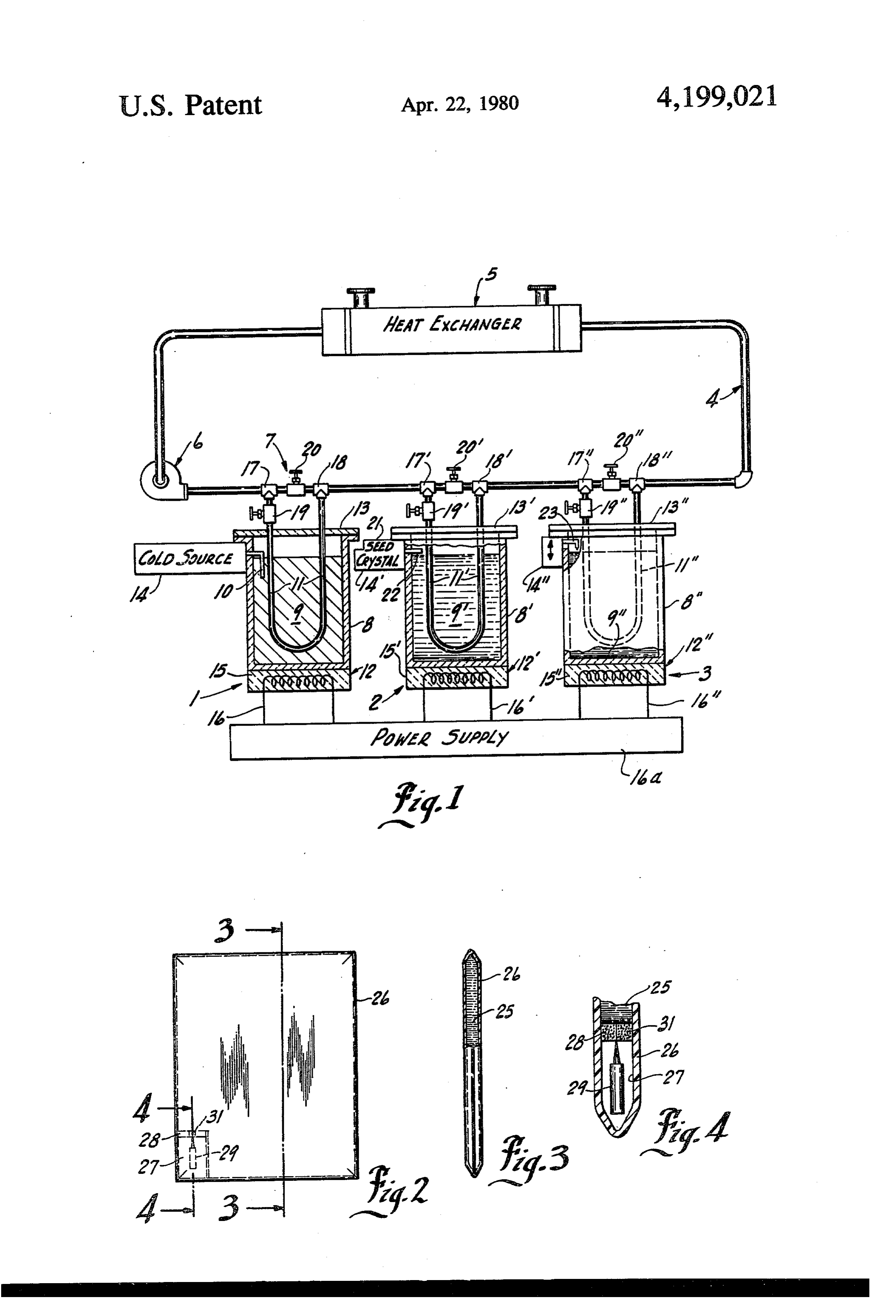
means is supported within the container and, in particu FIG. 1 is an illustration of a thermal storage energy lar, within the supercoolable material and connected system constructed in accordance with the present in through suitable valving to a fluid transport output line vention;
containing an efficient heat transfer fluid. In operation, 5 FIG. 2 is an illustration of a hot pad constructed in the heating unit is energized and the solid material accordance with the present invention; heated to above its melting temperature. The liquid is FIG. 3 is a vertical section taken generally on line then cooled below its melting temperature but above its 3-3 of FIG. 2; and spontaneous solidification temperature storing thermal onFIG. line 4 is an enlarged sectional view taken generally
energy. When heat is to be withdrawn from the super 20 cooled liquid, the valving system is open to pass the DESCRIPTION OF THE ILLUSTRATED transfer medium through the immersed conduit means EMBODIMENT and simultaneously the supercooled liquid is nucleated Referring to the drawing, the illustrated embodiment by activation of the nucleating element. The super of the invention in FIG. 1 includes three thermal energy cooled liquid freezes over a period of time which gener ally varies with the particular supercoolable material 25 storage cells or units, 1,2, and 3, each of which is simi larly constructed in accordance with the teaching of the and thereby generates and releases the heat of fusion present over a corresponding period. The time release of the nected toinvention. The three cells 1-3 are similarly con a main heat transfer line 4 which is connected thermal energy provides a source of energy which is to circulate a heat exchange medium to a thermal load transferred to the transfer medium in the conduit means.
The unit is regenerated by again actuating the heating 30 device device.
5 for supplying of thermal energy to the load
A pump 6 is shown for circulating of a suitable means to completely melt the material to above its melt liquid through line 4 and load 5. For example, the load ing temperature and then allowing the material to su device 5 may be a part of a room heating system for percool to again store thermal energy. conditioning of the room air. The thermal energy stor In a highly practical thermal storage system, a plural 35 age cells 1-3 are similarly connected to the main trans ity of individual cells such as described above are pro fer line 4 through similar valving systems 7 for selective vided. The conduit means are connected to the main withdrawal of thermal energy, in accordance with any transfer system with inlet and by-pass valving means for suitable automatic or manual control. selectively connecting of a cell in series with the main The illustrated cells 1-3 are essentially similarly con transfer line. Whenever heat is desired, a single cell may structed and cell 1 will be described in detail with corre be connected into the system. When additional heat is sponding elements of cells 2 and 3 identified by corre desired and the heat has been wholly or partially with sponding prime and double prime numbers for simplic drawn from a first cell, additional cell or cells may be ity and clarity of explanation. connected into the system. When the energy of a cell Generally, in accordance with the illustrated embodi has been depleted, such cell is disconnected and regen 45 ment of the invention, the thermal energy storing cell 1 erated immediately or at an appropriate later time. includes a container 8 in which a supercoolable material In other applications, other heating means, storage 9 is confined. A nucleating device 10 is secured within means and heat transfer means may of course be em the container 8 and is operable to trigger the supercool ployed. For example, a hot pad suitable for medical or able material 9 when in a supercooled liquid state, into therapeutic application may be constructed using a 50 nucleation with a freezing of the supercooled liquid and supercooling material, such as benzophenone, con the release of thermal energy. A conduit 11 is mounted tained in a sealed plastic bag. A nucleating device such within the container 8 passing through the supercoola as a pointed rod may be secured in an attached pocket ble material 9 and selectively connected to the heat having a self-sealing gland between the pocket and bag transfer line 4 for circulating of the transfer liquid proper. When the hot pad is to be used, the nucleating 55 through the conduit 11 for transfer of the heat from the device is pushed through the self-sealing gland to initi nucleated supercooled material 9 to the load 5. ate nucleation of the material. After nucleation, the The cell 1 further includes a suitable heating unit 12 nucleating device may be retracted. The heat generated to convert nucleated and solidified material 9 to a liquid as a result of freezing is applied to a desired location by state above its melting temperature. placing the plastic bag over the desired location with The present invention is particularly directed to the the container wall providing the heat transfer means. storage means. The heat exchange load 5 and intercon When the heat is completely expended, the entire bag necting system to cells 1-3 is, therefore, diagrammati with supercooling liquid is subjected to a suitable heat cally illustrated and no further description of a particu source such as an oven to obtain the liquid state again. lar load or the like is given other than to clearly explain By selection of a suitable supercoolable material, a tem 65 the illustrated embodiment of the present invention. perature responsive comfort unit can be provided. The material 9 may be of any suitable supercoolable Thus, an outdoor comfort pad may be provided by material. A supercoolable material 9 is capable of being selecting a supercoolable material with a spontaneous placed and maintained in a solid state to a given melting
Page 5
temperature level and alternately in a total liquid state ture and thereby storing of thermal energy within the upon reaching such level. Further, material 9 maintains liquid. If heat is desired, the valving system is opened to the liquid state even when cooled in the liquid state to connect the desired cell 1-3 into the transfer line 4 and below its melting temperature, which may be referred simultaneously the nucleating device 10 is activated to to in the art as the freezing temperature, but above a 5 trigger the supercooled liquid which nucleates and spontaneous freezing temperature. Thus, supercooling of most supercoolable liquids to a particular level, iden freezes, liberating the heat of fusion and producing a tified as the spontaneous nucleating temperature, results timed release of thermal energy. The liquid passing in spontaneous freezing and solidification of the mate through heat and the transfer conduit 11 absorbs this liberated transfers it to the main system and particularly rial 9, with a resulting release of the heat stored in the 10 the load liquid. The material in accordance with the present to More device 5.
particularly, the proper construction of con invention is selected with a significant supercooling tainer 8 for the supercoolable material 9 constitutes a capability and generally at least five F. and preferably significant feature for proper functioning of the cell. greater for providing a substantial level of energy stor Thus, the inner surface of the container 9 for most age. 15
The supercooled liquid in addition to spontaneous free supercoolable liquids must be smooth and essentially nucleation is also capable of being triggered into freez cooled of all imperfections. As noted previously, super ing or fusion while above the spontaneous nucleating ation liquids can generally be triggered into nucle temperature in a controlled manner by other than cool by a sharp pointed object. A sharp imperfection ing to the spontaneous nucleating temperature, and 20 on the inner surface of the container 8 could constitute thereby producing a timed release of the thermal energy anucleating nucleating means which would generate uncontrolled and freezing of the liquid. Contamination of upon initiation of the freezing of the supercooled liquid.
The supercoolable liquid may also be triggered to solid the supercoolable material 9 may also result in uncon ify by initiating solidification at a point or limited area. trolled nucleating similar to the addition of a seed crys For example, an element at a temperature below the 25 tal. The container therefore is preferably sealed to pro spontaneous nucleating temperature of the material tect the material and constructed with an inner smooth placed in the material may initiate the process which . wall which does not chemically react with the super coolable material 9.
will then rapidly propagate through the entire mass.
Similarly, a starting seed crystal may be introduced or shown In the illustrated embodiment, the container 8 is even a sharp pointed instrument inserted in the liquid 30 13, through as a cylindrical tank having a removable cover will act as a trigger means to initiate the nucleating and system, the containerwhich the conduit 11 passes. In a practical solidifying process. The supercooled liquid rather rap 8 may be formed of a soda lime idly begins to solidify from the initiating means, rising glass, which is readily formed as a smooth and essen to the melting temperature if sufficient energy is pres tially imperfection free container and which will not ent. However, the supercooled liquid cannot be heated 35 react with the supercoolable material. For example, particularly satisfactory supercoolable materials include above its melting temperature and, consequently, after benzophenone, 4-benzoylpyridine and ethylene carbon rising to the melting temperature, the supercooled liq uid decreases in solidification rate, with timed release of ate for application of normal environmental conditions. thermal energy. The trigger means may be removed Ethylenetemperature carbonate, for example, has a convenient after the process is started because of the self propagat 40 melting cooled to a temperature of 96 F. and can be readily super of around 50 F. without solidi ing characteristic thereof. However, in heating and storing of the energy, the material must be in a complete fication. The carbonate also has a relatively high heat of liquid state as any solid portion would function as a seed fusion being on the order of 2.40 kilocalories/mole, and crystal and immediately reverse the process upon re hasAlthough a heat capacity of 40.6 calories/1 C. mole. any other supercoolable material having a moval of the heat. 45
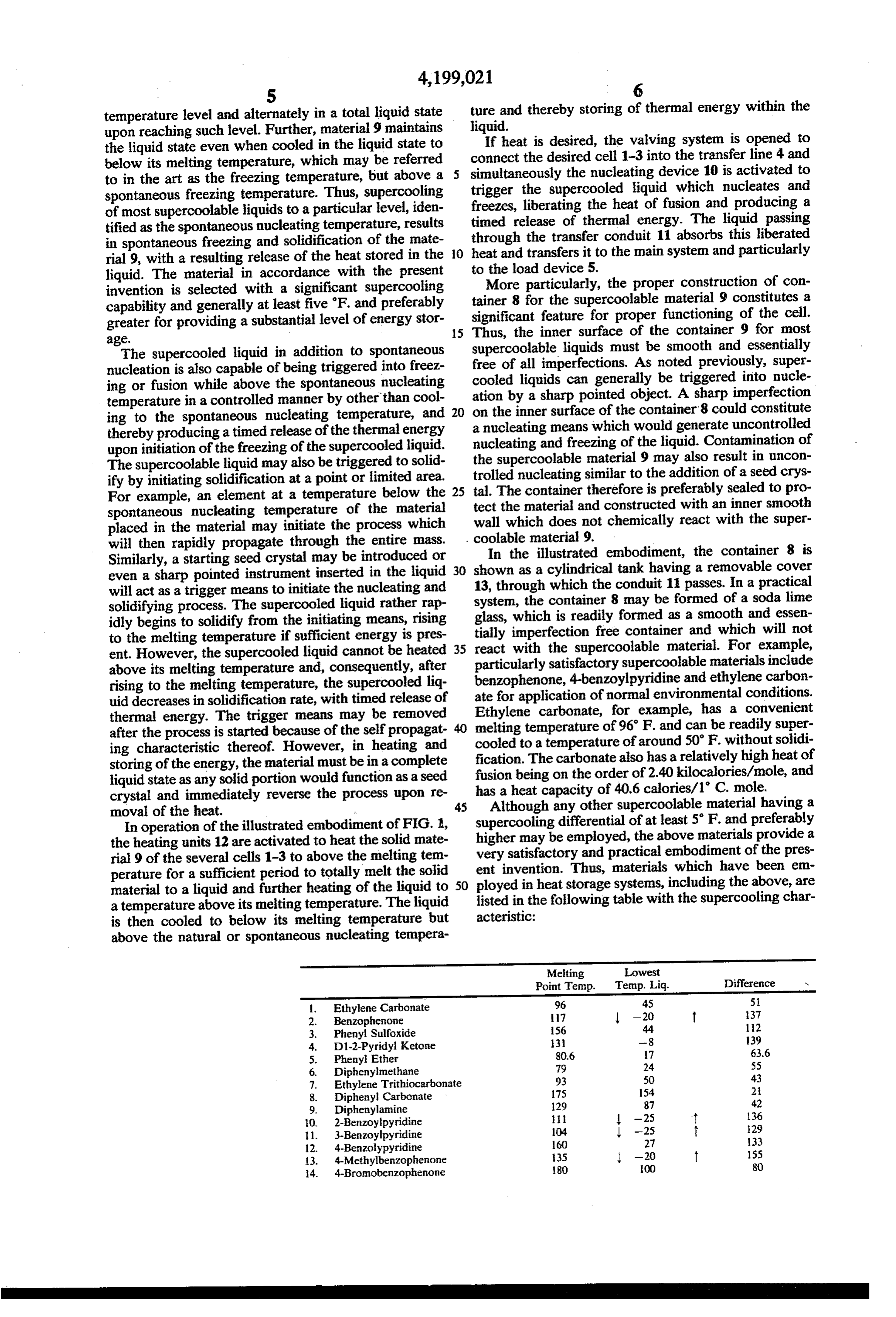
In operation of the illustrated embodiment of FIG. 1, supercooling differential of at least 5 F. and preferably the heating units 12 are activated to heat the solid mate higher may be employed, the above materials provide a rial 9 of the several cells 1-3 to above the melting tem very satisfactory and practical embodiment of the pres perature for a sufficient period to totally melt the solid ent invention. Thus, materials which have been en material to a liquid and further heating of the liquid to 50 ployed in heat storage systems, including the above, are a temperature above its melting temperature. The liquid listed in the following table with the supercooling char is then cooled to below its melting temperature but acteristic:
above the natural or spontaneous nucleating tempera
Melting Lowest
Point Temp. Temp. Liq. Difference w
Ethylene Carbonate 96 45 5.
Benzophenone 7 -20 t 37
Phenyl Sulfoxide 56 44 12
D1-2-Pyridyl Ketone 3. -8 139
Phenyl Ether 80.6 17 63.6
Diphenylmethane 79 24 55
Ethylene Trithiocarbonate 93 50 43
Diphenyl Carbonate 175 154 21
Diphenylamine 129 87 42 2-Benzoylpyridine -25 t 136 3-Benzoylpyridine 04 -25 t 29 4-Benzolypyridine 60 27 133 4-Methylbenzophenone 35 -20 t 155 4-Bromobenzophenone 180 00 80
Page 6
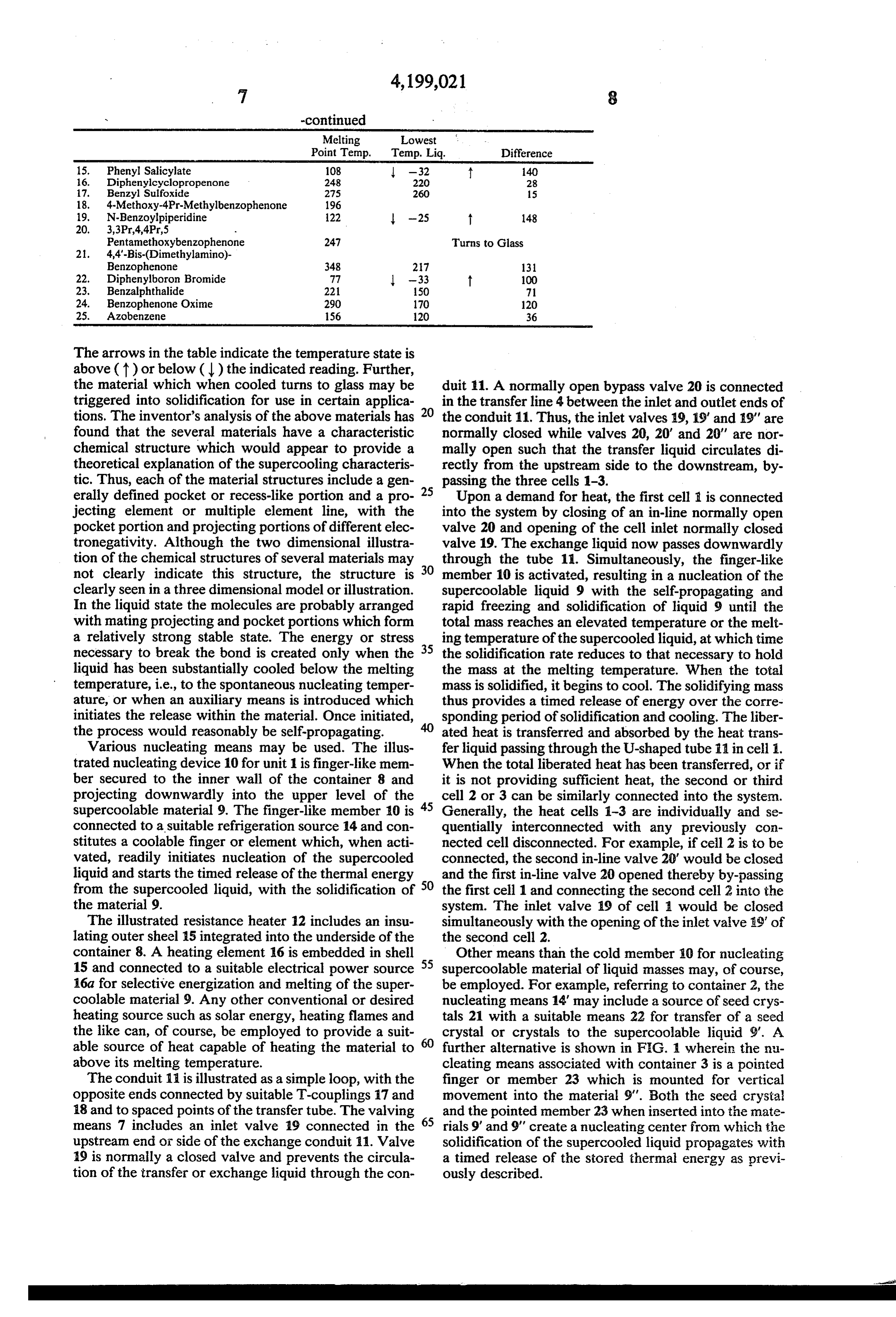
Melting Lowest
Point Temp. Temp. Liq. Difference 15. Phenyl Salicylate 108 -32 f 140 16. Diphenylcyclopropenone 248 220 28 17. Benzyl Sulfoxide 275 260 15
19. N-Benzoylpiperidine 122 -25 t 148
Pentamethoxybenzophenon 247 Turns to Glass
Benzophenone 348 27 13 22. Diphenylboron Bromide 77 -33 t 100 23. Benzalphthalide 221 150 71 24. Benzophenone Oxime 290 170 120 25. Azobenzene 156 120 36
The arrows in the table indicate the temperature state is above (t) or below () the indicated reading. Further, the material which when cooled turns to glass may be duit 11. A normally open bypass valve 20 is connected triggered into solidification for use in certain applica 20 in the transfer line 4 between the inlet and outlet ends of tions. The inventor's analysis of the above materials has the conduit 11. Thus, the inlet valves 19, 19' and 19" are found that the several materials have a characteristic normally closed while valves 20, 20' and 20' are nor chemical structure which would appear to provide a mally open such that the transfer liquid circulates di theoretical explanation of the supercooling characteris rectly from the upstream side to the downstream, by tic. Thus, each of the material structures include agen 25 passing the three cells 1-3.
erally defined pocket or recess-like portion and a pro Upon a demand for heat, the first cell it is connected jecting element or multiple element line, with the into the system by closing of an in-line normally open pocket portion and projecting portions of different elec valve 20 and opening of the cell inlet normally closed tronegativity. Although the two dimensional illustra valve 19. The exchange liquid now passes downwardly tion of the chemical structures of several materials may 30 through the tube 11. Simultaneously, the finger-like not clearly indicate this structure, the structure is member 10 is activated, resulting in a nucleation of the clearly seen in a three dimensional model or illustration. supercoolable liquid 9 with the self-propagating and In the liquid state the molecules are probably arranged rapid freezing and solidification of liquid 9 until the with mating projecting and pocket portions which form total mass reaches an elevated temperature or the melt a relatively strong stable state. The energy or stress 35 ing temperature of the supercooled liquid, at which time necessary to break the bond is created only when the the solidification rate reduces to that necessary to hold liquid has been substantially cooled below the melting the mass at the melting temperature. When the total temperature, i.e., to the spontaneous nucleating temper mass is solidified, it begins to cool. The solidifying mass ature, or when an auxiliary means is introduced which thus provides a timed release of energy over the corre initiates the release within the material. Once initiated, sponding period of solidification and cooling. The liber the process would reasonably be self-propagating. ated heat is transferred and absorbed by the heat trans Various nucleating means may be used. The illus fer liquid passing through the U-shaped tube 11 in cell 1. trated nucleating device 10 for unit 1 is finger-like mem When the total liberated heat has been transferred, or if ber secured to the inner wall of the container 8 and it is not providing sufficient heat, the second or third projecting downwardly into the upper level of the cell 2 or 3 can be similarly connected into the system. supercoolable material 9. The finger-like member 10 is 45 Generally, the heat cells 1-3 are individually and se connected to a suitable refrigeration source 14 and con quentially interconnected with any previously con stitutes a coolable finger or element which, when acti nected cell disconnected. For example, if cell 2 is to be vated, readily initiates nucleation of the supercooled connected, the second in-line valve 20' would be closed liquid and starts the timed release of the thermal energy and the first in-line valve 20 opened thereby by-passing from the supercooled liquid, with the solidification of 50 the first cell 1 and connecting the second cell 2 into the the material 9. system. The inlet valve 19 of cell a would be closed The illustrated resistance heater 12 includes an insu simultaneously with the opening of the inlet valve 9 of lating outer sheel 5 integrated into the underside of the the second cell 2.
container 8. A heating element 16 is embedded in shell 55 Other means than the cold member 10 for nucleating 15 and connected to a suitable electrical power source supercoolable material of liquid masses may, of course, 16.a for selective energization and melting of the super be employed. For example, referring to container 2, the coolable material 9. Any other conventional or desired nucleating means 14" may include a source of seed crys heating source such as solar energy, heating flames and tals 21 with a suitable means 22 for transfer of a seed the like can, of course, be employed to provide a suit crystal or crystals to the supercoolable liquid 9". A able source of heat capable of heating the material to further alternative is shown in F.G. wherein the nu above its melting temperature. cleating means associated with container 3 is a pointed The conduit 1 is illustrated as a simple loop, with the finger or member 23 which is mounted for vertical opposite ends connected by suitable T-couplings 17 and movement into the material 9'. Both the seed crystal 18 and to spaced points of the transfer tube. The valving 65 and the pointed member 23 when inserted into the mate means 7 includes an inlet valve 19 connected in the rials 9' and 9' create a nucleating center from which the upstream end or side of the exchange conduit 11. Valve solidification of the supercooled liquid propagates with 19 is normally a closed valve and prevents the circula a timed release of the stored thermal energy as previ tion of the transfer or exchange liquid through the con ously described.
Page 7
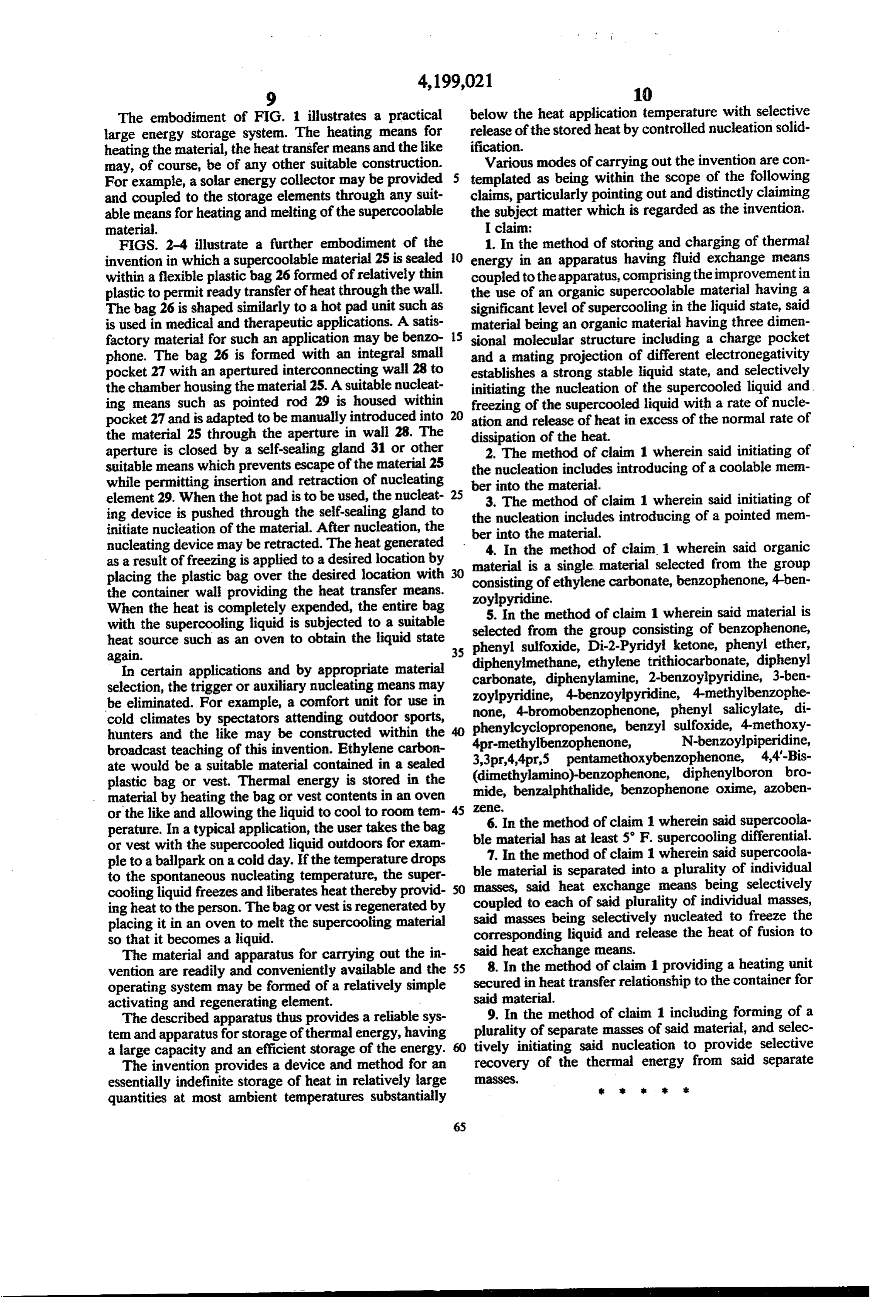
The embodiment of FIG. 1 illustrates a practical below the heat application temperature with selective large energy storage system. The heating means for release of the stored heat by controlled nucleation solid heating the material, the heat transfer means and the like ification.
may, of course, be of any other suitable construction. Various modes of carrying out the invention are con For example, a solar energy collector may be provided 5 templated as being within the scope of the following and coupled to the storage elements through any suit claims, particularly pointing out and distinctly claiming able means for heating and melting of the supercoolable the subject matter which is regarded as the invention. material. I claim:
FIGS. 2-4 illustrate a further embodiment of the 1. In the method of storing and charging of thermal invention in which a supercoolable material 25 is sealed 10 energy in an apparatus having fluid exchange means within a flexible plastic bag 26 formed of relatively thin coupled to the apparatus, comprising the improvementin plastic to permit ready transfer of heat through the wall. the use of an organic supercoolable material having a The bag 26 is shaped similarly to a hot pad unit such as significant level of supercooling in the liquid state, said is used in medical and therapeutic applications. A satis material being an organic material having three dimen factory material for such an application may be benzo 15 sional molecular structure including a charge pocket phone. The bag 26 is formed with an integral small and a mating projection of different electronegativity pocket 27 with an apertured interconnecting wall 28 to establishes a strong stable liquid state, and selectively the chamber housing the material 25. A suitable nucleat initiating the nucleation of the supercooled liquid and, ing means such as pointed rod 29 is housed within freezing of the supercooled liquid with a rate of nucle pocket 27 and is adapted to be manually introduced into 20 ation and release of heat in excess of the normal rate of the material 25 through the aperture in wall 28. The dissipation of the heat.
aperture is closed by a self-sealing gland 31 or other 2. The method of claim 1 wherein said initiating of suitable means which prevents escape of the material 25 the nucleation includes introducing of a coolable mem while permitting insertion and retraction of nucleating ber into the material.
element 29. When the hot pad is to be used, the nucleat 25 3. The method of claim 1 wherein said initiating of ing device is pushed through the self-sealing gland to the nucleation includes introducing of a pointed mem initiate nucleation of the material. After nucleation, the nucleating device may be retracted. The heat generated ber4.into In the material.
the method of claim. 1 wherein said organic as a result of freezing is applied to a desired location by material is a single material selected from the group placing the plastic bag over the desired location with consisting of ethylene carbonate, benzophenone, 4-ben
the container wall providing the heat transfer means.
When the heat is completely expended, the entire bag zoylpyridine.
5. In the method of claim 1 wherein said material is with the supercooling liquid is subjected to a suitable selected from the group consisting of benzophenone, heat source such as an oven to obtain the liquid state 35 phenyl sulfoxide, Di-2-Pyridyl ketone, phenyl ether, again.
In certain applications and by appropriate material carbonate, diphenylamine, trithiocarbonate, diphenylmethane, ethylene diphenyl
Selection, the trigger or auxiliary nucleating means may zoylpyridine, 4-benzoylpyridine, 4-methylbenzophe be eliminated. For example, a comfort unit for use in none, 4-bromobenzophenone, phenyl salicylate, di cold climates by spectators attending outdoor sports, phenylcyclopropenone, benzyl sulfoxide, 4-methoxy hunters and the like may be constructed within the broadcast teaching of this invention. Ethylene carbon 4pr-methylbenzophenone, N-benzoylpiperidine, 3,3pr,4,4pr,5 pentamethoxybenzophenone, 4,4'-Bis ate would be a suitable material contained in a sealed plastic bag or vest. Thermal energy is stored in the (dimethylamino)-benzophenone, diphenylboron bro mide, benzalphthalide, benzophenone oxime, azoben material by heating the bag or vest contents in an oven Zaee.
or the like and allowing the liquid to cool to room tem perature. In a typical application, the user takes the bag ble6.material
In the method of claim 1 wherein said supercoola has at least 5 F. supercooling differential.
or vest with the supercooled liquid outdoors for exam ple to a ballpark on a cold day. If the temperature drops ble7.material
In the method of claim 1 wherein said supercoola to the spontaneous nucleating temperature, the super masses, said isheat separated into a plurality of individual exchange means being selectively cooling liquid freezes and liberates heat thereby provid coupled to each of said plurality of individual masses, ing heat to the person. The bag or vest is regenerated by said masses placing it in an oven to melt the supercooling material correspondingbeing selectively nucleated to freeze the liquid and release the heat of fusion to so that it becomes a liquid.
The material and apparatus for carrying out the in said8. heat exchange means.
In the method of claim 1 providing a heating unit vention are readily and conveniently available and the 55 operating system may be formed of a relatively simple secured in heat transfer relationship to the container for activating and regenerating element. said material.
The described apparatus thus provides a reliable sys 9. In the method of claim 1 including forming of a tem and apparatus for storage of thermal energy, having plurality of separate masses of said material, and selec a large capacity and an efficient storage of the energy. tively initiating said nucleation to provide selective The invention provides a device and method for an recovery of the thermal energy from said separate essentially indefinite storage of heat in relatively large aSSeS.
quantities at most ambient temperatures substantially
Page 8
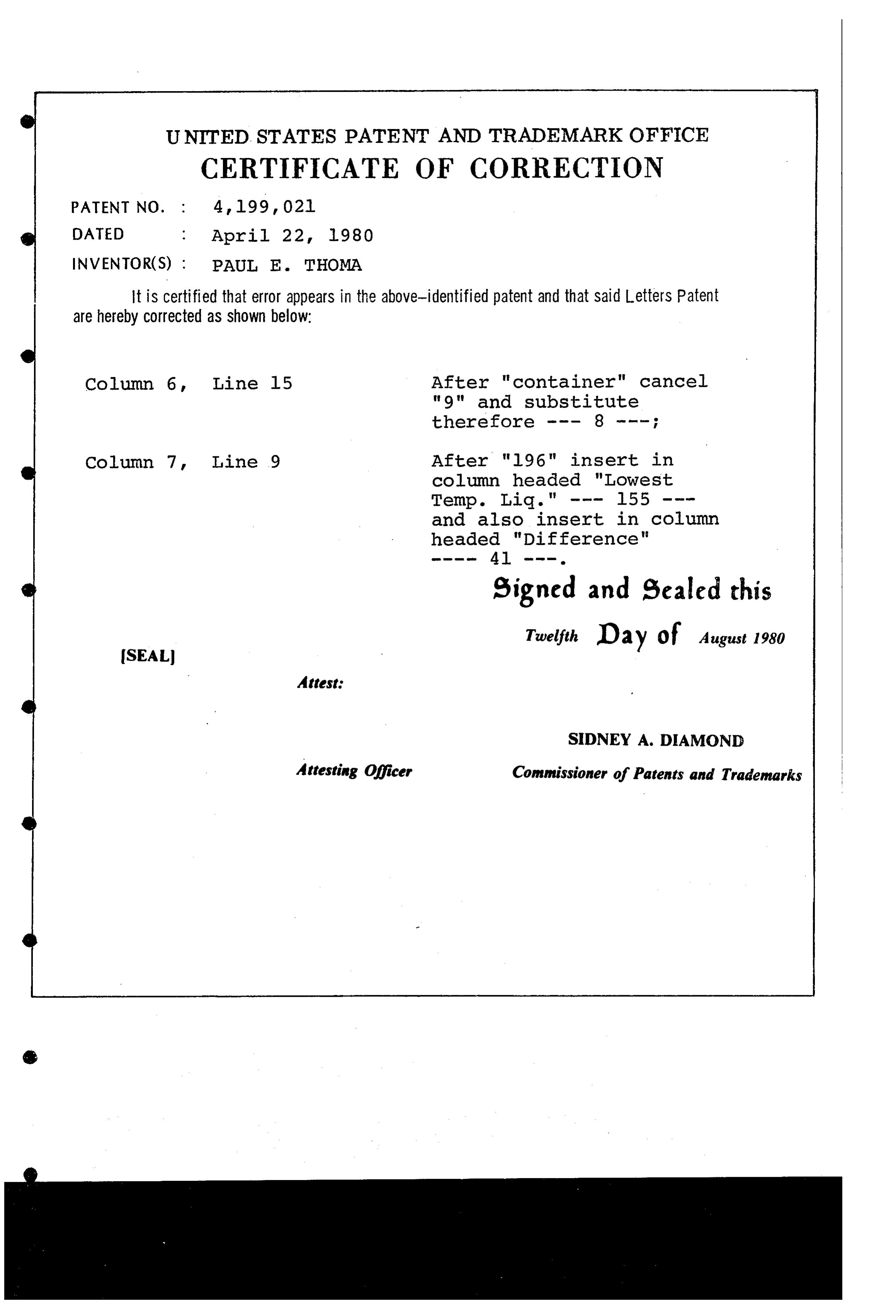
UNITED STATES PATENT AND TRADEMARK OFFICE
CERTIFICATE OF CORRECTION
INVENTOR(S) : PAUL E. THOMA
It is certified that error appears in the above-identified patent and that said Letters Patent are hereby Corrected as shown below:
Column 6, Line l5 After "container" cancel "9" and substitute
Column 7, Line 9 After "96" insert in column headed "LOWest
and also insert in column headed "Difference"
signed and sealed this
Twelfth Day of August 1980
SIDNEY A. DAMOND
Attesting Officer Commissioner of Patents and Trademarks
Provenance
- Collection
- Cited prior art
- Original PDF
- patentimages.storage.googleapis.com →
- Filed
- 1976-11-24
- Pages
- 8
- Method
- pdftotext (the PDF's own text layer) + pdftoppm 300dpi page scans
- Source
- Google Patents bibliographic record
- Granted
- 1980-04-22
- Inventors
- Paul E. Thoma; Johnson Controls Inc
- Transcribed from
- patentimages.storage.googleapis.com →