patent · US3375664
Convection current power generator
2 April 1968
Page 1
Drawing sheet — no readable text.
Page 2
United States Patent Office 3,375,664 Patented Apr. 2, 1968
3,375,664 tion of one of the leg members supplies a measured
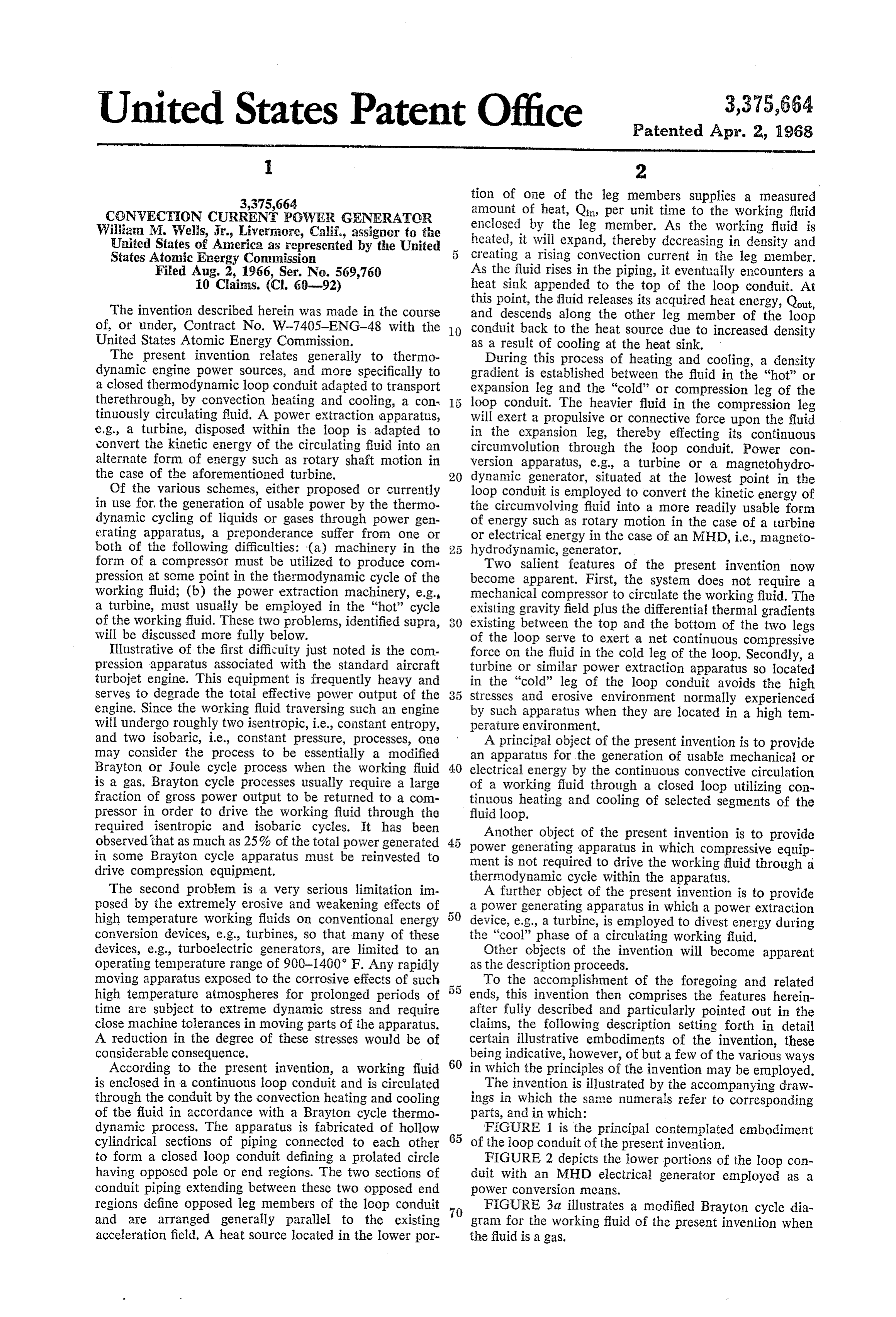
CGNVECTION CURRENT POWER GENERATOR amount of heat, Qin, per unit time to the working fluid Willian M. Weis, Jr., Livermore, Calif., assignor to the enclosed by the leg member. As the working fluid is United States of America as represented by the United 5 heated, it will expand, thereby decreasing in density and States Atomic Energy Commission creating a rising convection current in the leg member. Filed Aug. 2, 1966, Ser. No. 569,760 As the fluid rises in the piping, it eventually encounters a 10 Cains. (C. 60-92) heat sink appended to the top of the loop conduit. At The invention described herein was made in the course this point, the fluid releases its acquired heat energy, Qout, and descends along the other leg member of the loop of, or under, Contract No. W-7405-ENG-48 with the O conduit back to the heat source due to increased density United States Atomic Energy Commission. as a result of cooling at the heat sink. The present invention relates generally to thermo During this process of heating and cooling, a density dynamic engine power sources, and more specifically to gradient is established between the fluid in the “hot” or a closed thermodynamic loop conduit adapted to transport expansion leg and the "cold' or compression leg of the therethrough, by convection heating and cooling, a con loop conduit. The heavier fluid in the compression leg tinuously circulating fluid. A power extraction apparatus, will exert a propulsive or connective force upon the fluid e.g., a turbine, disposed within the loop is adapted to in the expansion leg, thereby effecting its continuous convert the kinetic energy of the circulating fluid into an circumvolution through the loop conduit. Power con alternate form of energy such as rotary shaft motion in version apparatus, e.g., a turbine or a magnetohydro the case of the aforementioned turbine. 20 dynamic generator, situated at the lowest point in the Of the various schemes, either proposed or currently loop conduit is employed to convert the kinetic energy of in use for the generation of usable power by the thermo the circumvolving fluid into a more readily usable form dynamic cycling of liquids or gases through power gen of energy such as rotary motion in the case of a turbine erating apparatus, a preponderance suffer from one or or electrical energy in the case of an MHD, i.e., magneto both of the following difficulties: (a) machinery in the hydrodynamic, generator.
form of a compressor must be utilized to produce com Two salient features of the present invention now pression at some point in the thermodynamic cycle of the become apparent. First, the system does not require a working fluid; (b) the power extraction machinery, e.g. mechanical compressor to circulate the working fluid. The a turbine, must usually be employed in the “hot” cycle existing gravity field plus the differential thermal gradients of the working fluid. These two problems, identified supra, existing between the top and the bottom of the two legs will be discussed more fully below. of the loop serve to exert a net continuous compressive Illustrative of the first difficulty just noted is the com force on the fluid in the cold leg of the loop. Secondly, a pression apparatus associated with the standard aircraft turbine or similar power extraction apparatus so located turbojet engine. This equipment is frequently heavy and in the “cold' leg of the loop conduit avoids the high serves to degrade the total effective power output of the 3 5 stresses and erosive environment normally experienced engine. Since the working fluid traversing such an engine by such apparatus when they are located in a high tem will undergo roughly two isen tropic, i.e., constant entropy, perature environment.
and two isobaric, i.e., constant pressure, processes, one A principal object of the present invention is to provide may consider the process to be essentially a modified an apparatus for the generation of usable mechanical or Brayton or Joule cycle process when the working fluid 40 is a gas. Brayton cycle processes usually require a large electrical energy by the continuous convective circulation of a working fluid through a closed loop utilizing con fraction of gross power output to be returned to a com tinuous heating and cooling of selected segments of the pressor in order to drive the working fluid through the fluid loop.
required isentropic and isobaric cycles. It has been Another object of the present invention is to provide observed that as much as 25% of the total power generated power generating apparatus in which compressive equip in some Brayton cycle apparatus must be reinvested to ment is not required to drive the working fluid through a drive compression equipment. thermodynamic cycle within the apparatus. The second problem is a very serious limitation im A further object of the present invention is to provide posed by the extremely erosive and weakening effects of a power generating apparatus in which a power extraction high temperature working fluids on conventional energy device, e.g., a turbine, is employed to divest energy during conversion devices, e.g., turbines, so that many of these the “cool” phase of a circulating working fluid. devices, e.g., turboelectric generators, are limited to an Other objects of the invention will become apparent operating temperature range of 900-1400 F. Any rapidly as the description proceeds.
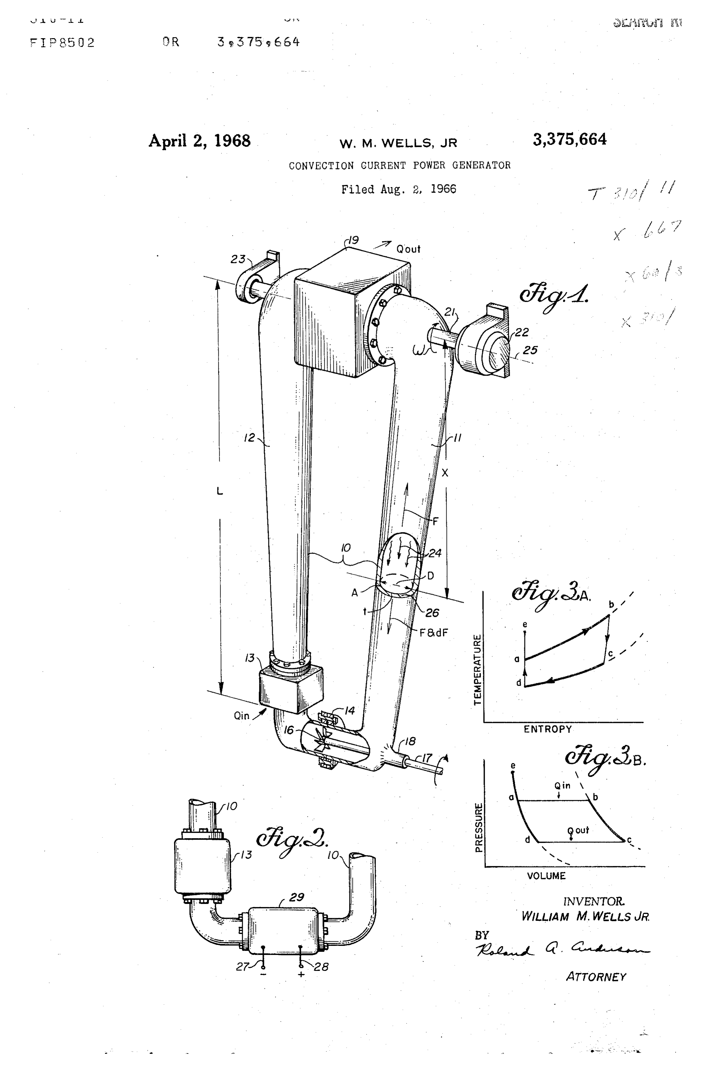
moving apparatus exposed to the corrosive effects of such To the accomplishment of the foregoing and related high temperature atmospheres for prolonged periods of ends, this invention then comprises the features herein time are subject to extreme dynamic stress and require after fully described and particularly pointed out in the close machine tolerances in moving parts of the apparatus. claims, the following description setting forth in detail A reduction in the degree of these stresses would be of certain illustrative embodiments of the invention, these considerable consequence. being indicative, however, of but a few of the various ways According to the present invention, a Working fluid 60 in which the principles of the invention may be employed. is enclosed in a continuous loop conduit and is circulated The invention is illustrated by the accompanying draw through the conduit by the convection heating and cooling ings in which the same numerals refer to corresponding of the fluid in accordance with a Brayton cycle thermo parts, and in which:
dynamic process. The apparatus is fabricated of hollow 65 FIGURE 1 is the principal contemplated embodiment cylindrical sections of piping connected to each other of the loop conduit of the present invention. to form a closed loop conduit defining a prolated circle FIGURE 2 depicts the lower portions of the loop con having opposed pole or end regions. The two sections of duit with an MHD electrical generator employed as a conduit piping extending between these two opposed end power conversion means.
regions define opposed leg members of the loop conduit FIGURE 3a illustrates a modified Brayton cycle dia and are arranged generally parallel to the existing 70 gram for the working fluid of the present invention when acceleration field. A heat source located in the lower por the fluid is a gas.
Page 3
FIGURE 3b illustrates an ideal P-V program for the ator employing these principles and suitable for use working fluid in the system of the present invention when in the present invention is disclosed in an article en the fluid is a gas. titled “MHD with Liquid Metai' by H. E. Weber and Referring now to the drawings, in FIGURE 1 there C. H. Marston, Mechanical Engineering, August 1964, is shown one embodiment of a loop conduit 10 con pp. 34-37. The apparatus disclosed in the above article prising a "cold' of compression leg member 1 and employs a spinning annulus of conducting fiuid as an a "hot' or expansion leg member 12. Located in the "armature' situated in a magnetic field. Although the lower portion of the expansion leg member 12 between reference article describes the fluid "armature' as driven points a and b referring to the diagrams of FIGURE by a high pressure, high temperature vapor, the appara 3a and FIGURE 3b of the loop conduit 10 is a heat O tus is readily adaptable for use in the compression leg Source 13. Typically, this heat source 13 is a nuclear of the present invention by injecting the high pressure reactor core disposed within and enclosed by leg mem cooled fuid located at the bottom of the leg member ber 12, a heat exchanger apparatus located within leg into the rotating fluid “armature' in order to spin it 2 and connected to an external heat source (not shown), within the magnetic field created inside the MHD gen or other equivalent device for delivering a specified quan erator. An alternate location for the MHD generator tity of heat, Qin, to a working fluid disposed therein. of the present invention is in the expansion leg if above Situated between points a and e (FIGURES 3a and the heat source 3. In this location, the fluid "armature' 3b) of the loop conduit 10 and near the juncture i4 of the generator is driven by the high temperature vapor of leg member 1 with leg member 12 is a prime mover, rising upwardly from heat sink 13. Electrical power gen i.e., an apparatus designed to derive and modify force erated by the MHD device is extracted via terminals 27 and motion from the circulating working fluid to drive and 28 as shown in FIGURE 2.
external machinery (not shown). The prime mover can In operation, the pressure density gradient established be in the form of a turbine 6 with a rotatable shaft between the fiuid in the compression leg and the ex 17 egressing through a support bearing 8 in the lower pansion leg of the loop conduit serves to maintain a portion of leg member 11. The emergence of shaft 7 continuous circulation of the working fluid around the through leg member 11 is not a strict requirement; shaft conduit. Proper placement of the heat sink 19 as shown 17 may also be directed through a similar support bear in FIGURE 1 is critical to the efficient operation of the ing (not shown) in the lower portion of leg member present invention. The heat sink 19 must be positioned 2 or by other equivalent means. midway between leg members Ei and 2 as shown in At the top portion of loop conduit 10 between leg FIGURE 1, or displaced slightly in the direction of the members 11 and 12 and between points c and d referring compression leg 1. In either of the two locations noted to the diagrams of FIGURES 3a and 3b of the loop above, the momentum of the fluid rising in the expansion conduit is a heat sink 19 arranged to extract a given leg will propel the densified working fluid in the heat quantity of heat, Qout, from the working fluid. As in sink over into the compression leg. Relocation of the the case of the heat source i3, the heat sink 9 may com heat sink in the expansion leg could result in a back flow prise conventional radiator schemes suitable for the ex of condensed fluid descending the expansion leg into traction of heat from a working fluid, e.g., a radiator the heat Source with a consequent decrease in the net which exposes a maximal surface area to a separate cool efficiency of the system.
ing fluid, or radiates heat into a heat sink such as the Another critical parameter associated with the present vacuum of Space, etc. With the foregoing arrangement, 40 invention relates to the location of the heat source. For a working fluid, e.g., water, inert gas, liquid metal or the most efficient operation of the present invention, the like disposed in the loop circuit will generally be this component must be situated in the lower portion of heated by Source 13, rise in conduit leg 12, be cooled either leg member 11 or 12 of the loop conduit. Unlike and densified in heat sink 19, descend in conduit leg the heat sink, the heat source cannot be located at the and expend its energy in prime mover 14, and then juncture 14 (FIGURE 1) of leg members 11 and 12 return to heat source 13 for recycling. Since at this location the fluid motions would no longer While the apparatus may be operated in a natural be unidirectional and will attempt to ascend both leg gravity field generally parallel to leg portions 11, 2, members simultaneously, thereby rendering the device in in space applications and for compactness a centrifugal operative.
acceleration field is preferred. To obtain such a fied 50 The fluid employed in the cycling process of the present there is attached to the top of loop conduit 10 a rigid, invention may exist in either a single or two-phase state rotatable shaft 21 engaged at one of its end portions during its transit around the loop conduit, depending, in to a rotator means 22 and supported at the other end part, on the operating temperature ranges within the loop point by a stationary bearing structure 23. The loop con conduit. In a single phase state, the working fluid will re duit 16 is then rotated as a unit around the axis 25 of 5 5 main either in a gaseous or in a liquid condition as it shaft 21. traverses both the heat sink and the heat source of the In FIGURE 2, there is shown the lower portions of loop conduit. In the two-phase state, the working fluid the loop conduit 10 of FIGURE 1, modified to include will be vaporized during its passage through the heat an MHD electric generator 29 in lieu of the turbine 16. Source and will be liquified while traversing the heat sink. The MHD generator 29 is affixed at the juncture 14 of 60 It is possible to operate the present invention utilizing a leg members 1 and 12 as shown in FIGURE 2. The mixture of a single-phase fluid with a double phase fluid or principle of operation of an MHD generator, as in the by employing exclusively either a single or a double phase case of a conventional wire wound generator, is based fluid, available coolants, heat transfer agents, and even on Faraday's law which states that the electromotive refrigerant compositions can be used to accommodate force (voltage) induced in a circuit is proportional to 65 requisite temperature conditions at high temperatures. the time rate of change of the magnetic flux through To further illustrate the operation of the present in the circuit. vention, it is desirable to understand in greater detail In the case of a conventional generator, this circuit the function and specification of the two leg members comprises a wire wound armature rotating in a mag 1 and 12. In addition to providing structural support netic field. The MHD generator employs a high velocity, O for the heat Source 13, the turbine 16, and the heat sink electrically conductive fluid, e.g., salt water, ionized 19, as shown in FIG. 1, and serving as an efficient path gases, mercury, cesiurn, potassium, etc., traversing a Way for confining the pressurized working fiuid 24, leg magnetic field to create an electrical current flow within members 1 and 12 must also function as highly efficient the fluid that will be perpendicular in direction to both heat insulators. For the loop conduit to operate properly, the magnetic field and the fluid flow. An MHD gener 5 heat must be prevented from escaping from the fluid in
Page 4
the expansion leg, and the fluid in the compression leg Rearranging Equation 5 will now produce the required must be prevented from absorbing heat. The use of struc expression for A:
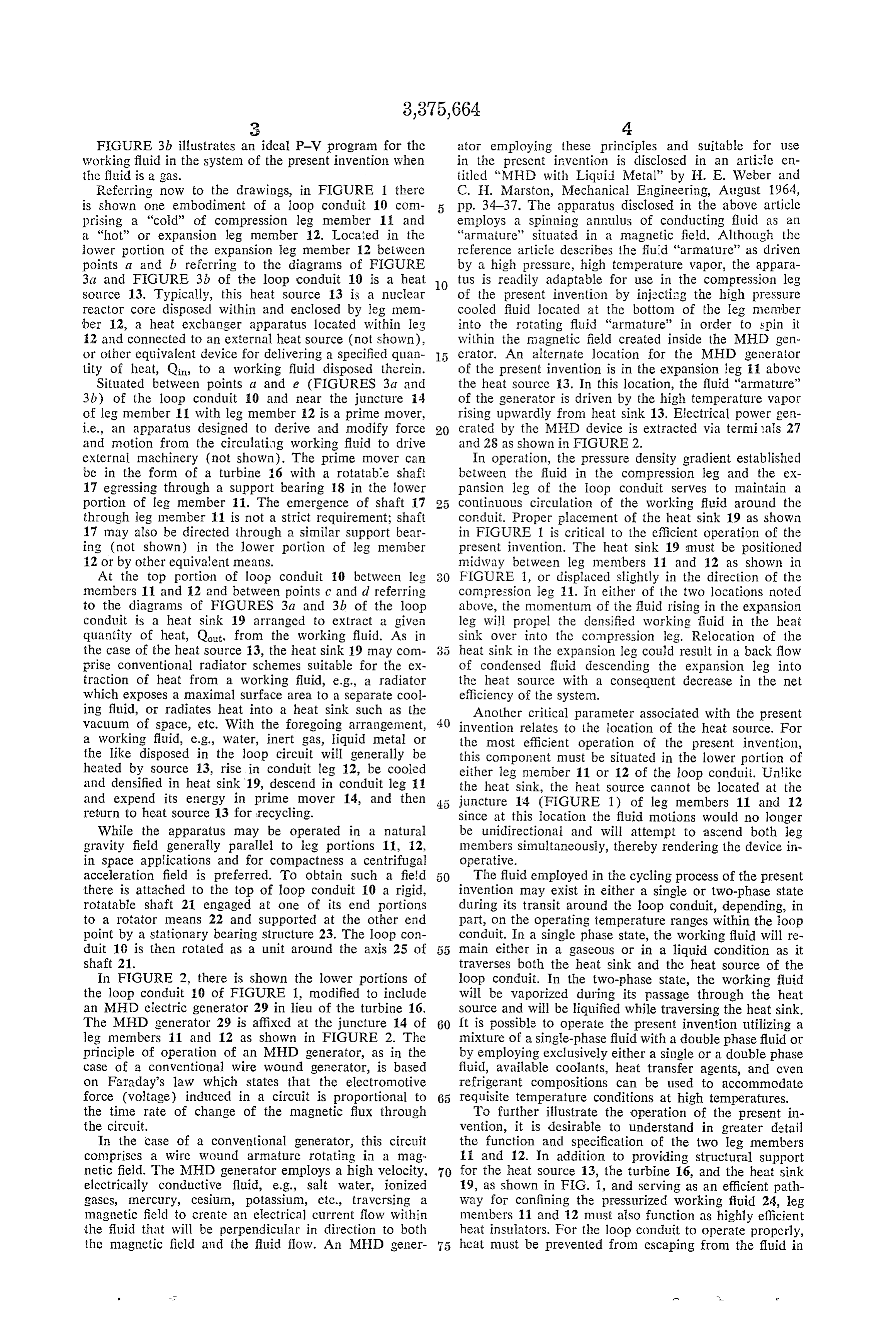
tural materials of very low thermal conductivity for use in leg members 11 and 12 is one satisfactory method of (6) A TD eXp. 2o. handling this problem.
To better comprehend the method of operation of the present invention, it is necessary to formulate relationships
Having obtained an expression for the cross sectional between the cross sectional area A, the mass M, and the area A of leg member 1 at any point x along its length, wall thickness t of the loop conduit 10 in terms of the one may now determine the radial wall thickness t at any various parameters associated with the system. We first 0 point along leg member 1. The cross sectional area. A consider a cross sectional annulus 26 of conduit piping at any point along leg member 1 can be given alternately located along leg member 11 at a distance x from the by the expression:
rotational axis 25, as shown in FIGURE 1. To facilitate (7) explanation, the following notation will be used:
dx-the longitudinal thickness of the pipe cross sectional 15
Substituting Equation 6 into Equation 8 and rearrang disk 26 as shown in FIG. 1.
x-the distance of pipe cross sectional disk 26 from the ing terms, one now obtains the desired equation for t: axis of rotation 25. (8) t-the wall thickness of pipe annulus 26 as shown in FIG 20
URE 1.
L-the total length of leg member 11.
A-the radial pipe cross sectional area of annulus 26 as shown in FIG. 1.
M-total pipe mass for leg member 11. Finally, to obtain an expression for the mass M of dM-mass of disk 26. leg member 11, it should be recalled that the mass of p-pipe density. disk 26 is given by the expression dM=pAdX. Integra o-tensile stress along pipe leg member 1. tion of this expression and substituting into it the value for F-total tensile force along pipe leg member 11, acting on A shown by Equation 7, one obtains the desired result: anulus 26 in the direction of fluid flow 24 within leg 30 member 11.
dF-increment of total tensile force. (9) parD2 "e2 (L-f)da w-angular velocity of rotation of leg member 11 around 2(F-1)
axis 25.
D-inner diameter of annulus 26 as shown in FIGURE 1. It is now instructive to consider two possible modes Pe-internal pressure at point e along loop conduit 11. of operation. The first is that of operation in a natural By Newton's second law, the forces acting upon annulus gravity field. The second includes spinning the loop con 26 are given by the expression: duit 0 around an axis 25 to provide a matched system of paired units rotating, as in space, about an axis there (1) between, or to produce an artificial "gravity” field within 40 the loop conduit. This second operation would be applica
However, since it is obvious that dM=pAdx and by ble to situations in which the natural gravity field is definition F=oA where all the piping in the conduit loop extremely weak or non-existent, such as in space. In both 10 is designed such that a will be constant, one can re instances, the design parameters of the present invention arrange Equation 1 to read: are essentially similar. For instance, Equation 8 states 45 that the thickness t of leg member 11 increases in going (2) d4 -2O ada from the bottom to the top of loop conduit ii). This in A. crease is achieved by maintaining a constant internal
Integration of Equation 2 yields the expression: diameter D throughout the loop 10 while varying the ex ternal diameter to satisfy Equation 8. Also, it is observed
2 that the mass M and the cross sectional area A of leg 2g member 11 will increase in a similar fashion while travel ing from the bottom to the top of loop conduit 10. This where C is a constant of integration. To evaluate C, one "tapering” of the external diameter of leg member 1 can may consider the following boundary conditions: at x=L, be perceived as a means for maintaining a constant tensile A will equal the cross sectional area Aend of the leg men 5 5 stress a as every point along the leg member 1. ber 11 at point e of the loop conduit 11. This expression Although the foregoing analysis was presented for the can be shown to equal compression leg ii, the same analysis and conclusions pertain with equal validity to the expansion leg 12. The
only difference in the analysis presented for leg 12 as
2(t–1) 60 compared with that for leg 12 relate to the resultant values for M, A, and t which will be slightly smaller in the expansion leg 2 than in the compression leg 11 due
Substituting this information into Equation 3 produces an to the decreased fluid pressure existing in this leg as com expression for C given by: pared with leg 11, discussed below. For purposes of elucidation, it will be assumed that the working fluid of the present invention is a gas, and
(i) ; in this instance an ideal gas. In a specific system, the working fluid could be a liquid, a gas, or a combination
Substituting Equation 4 into Equation 3 yields the re 70 of in a a liquid and a gas. Furthermore, the working fluid real system will not be ideal, and therefore its prop lationship: erties can be expected to depart from those of an ideal working fluid in a manner understood in the art.
in 'F'l-Fate) Referring to FIGURES 3a and 3b, as the working gas TD2 T2, 24 travels from point a to point b of the loop conduit 75 10 as shown in FIGURE 1, temperature and volume
Page 5
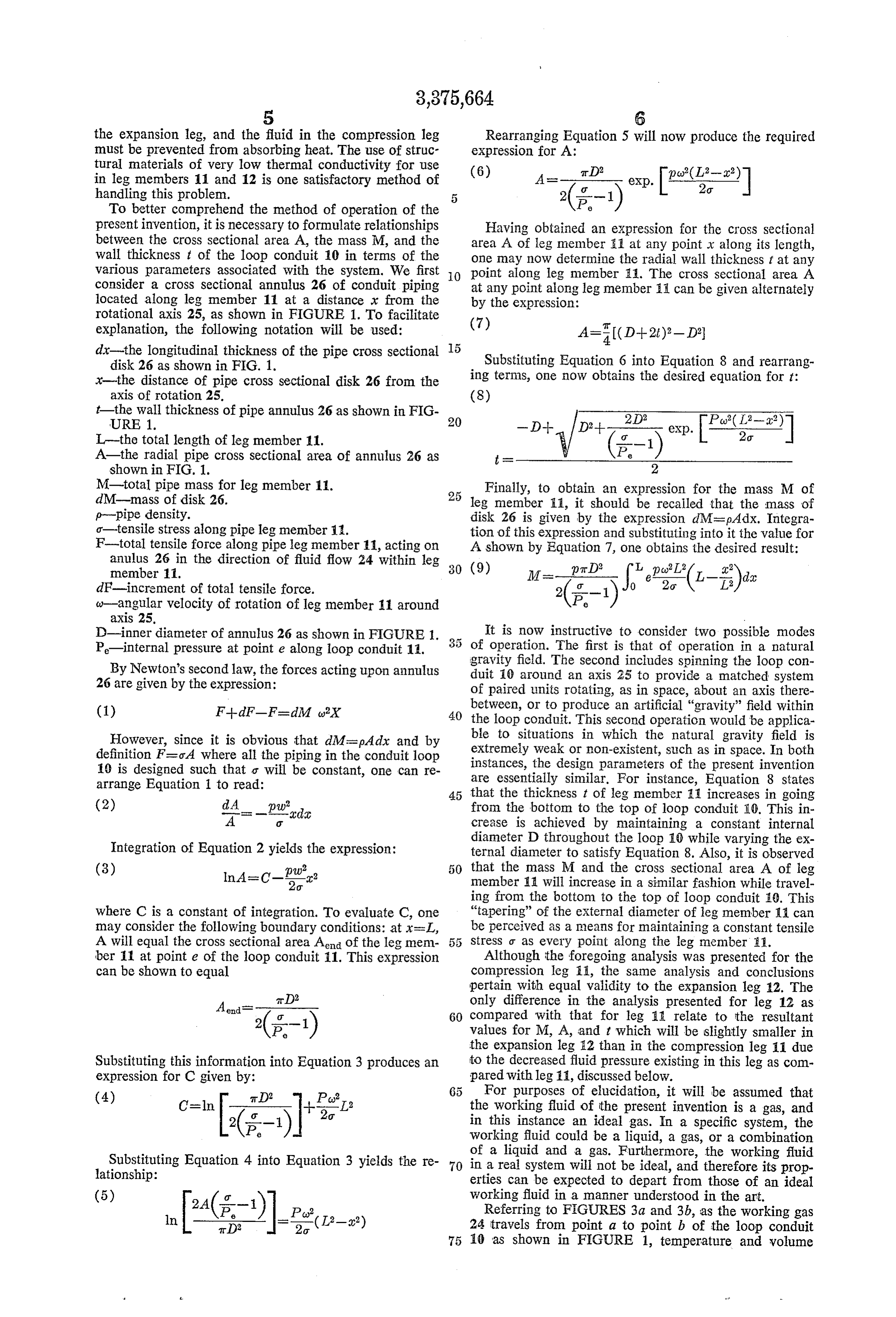
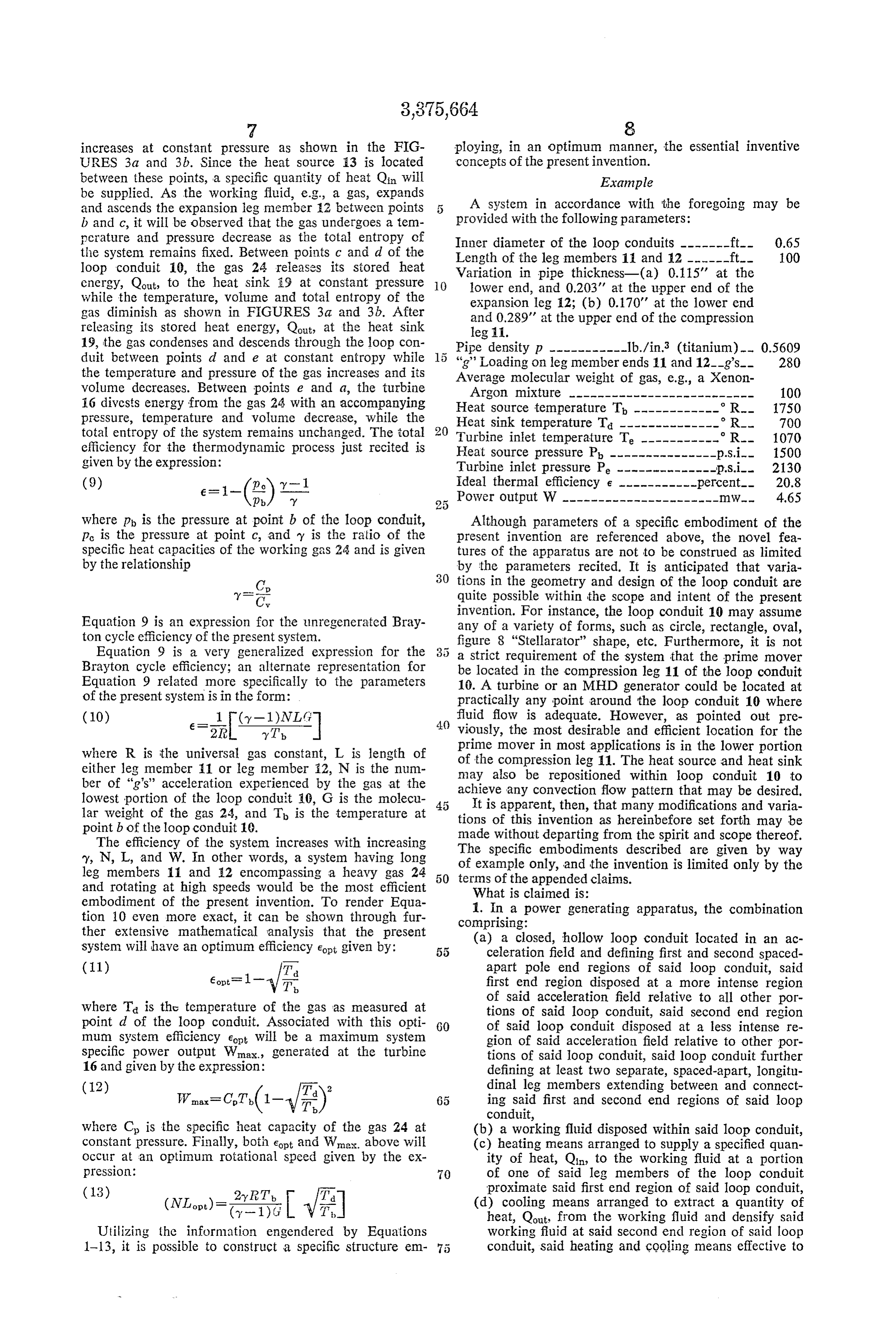
increases at constant pressure as shown in the FIG ploying, in an optimum manner, the essential inventive URES 3a and 3b. Since the heat source i3 is located concepts of the present invention. between these points, a specific quantity of heat Qin will Example be supplied. As the working fluid, e.g., a gas, expands and ascends the expansion leg member 2 between points A system in accordance with the foregoing may be b and c, it will be observed that the gas undergoes a tem provided with the following parameters: perature and pressure decrease as the total entropy of Inner diameter of the loop conduits -------ft.-- 0.65 the system remains fixed. Between points c and d of the Length of the leg members 11 and 12 ------ft.-- 100 loop conduit 10, the gas 24 releases its stored heat Variation in pipe thickness-(a) 0.115' at the energy, Qout, to the heat Sink 9 at constant pressure O lower end, and 0.203' at the upper end of the while the temperature, volume and total entropy of the expansion leg 2; (b) 0.170' at the lower end gas diminish as shown in FIGURES 3a and 3b. After and 0.289' at the upper end of the compression releasing its stored heat energy, Qout, at the heat sink leg 11.
19, the gas condenses and descends through the loop con Pipe density P -----------1b./in.3 (titanium) -- 0.5609 duit between points d and e at constant entropy while ''g'' Loading on leg member ends 1 and 12-g's-- 280 the temperature and pressure of the gas increases and its Average molecular weight of gas, e.g., a Xenon volume decreases. Between points e and a, the turbine Argon mixture -------------------------- 100 16 divests energy from the gas 24 with an accompanying Heat Source temperature T ------------ R 750 pressure, temperature and volume decrease, while the Heat sink temperature Ta -------------- R. 700 total entropy of the system remains unchanged. The total Turbine inlet temperature Te ----------- R. 1070 efficiency for the thermodynamic process just recited is Heat Source pressure Pb ---------------p.s. i. 1500 given by the expression: Turbine inlet pressure Pe --------------p.s. i. 2130 (9) e = - E) Y-l ideal thermal efficiency e -----------percent - 20.8 b my Power output W---------------------- mW-- 4.65 where p is the pressure at point b of the loop conduit, Although parameters of a specific embodiment of the pe is the pressure at point c, and y is the ratio of the present invention are referenced above, the novel fea specific heat capacities of the working gas 24 and is given tures of the apparatus are not to be construed as limited by the relationship by the parameters recited. It is anticipated that varia 30 tions in the geometry and design of the loop conduit are quite possible within the scope and intent of the present
Equation 9 is an expression for the unregenerated Bray invention. For instance, the loop conduit 10 may assume ton cycle efficiency of the present system. any of a variety of forms, such as circle, rectangle, oval, Equation 9 is a very generalized expression for the figure 8 "Stellarator' shape, etc. Furthermore, it is not Brayton cycle efficiency; an alternate representation for a strict requirement of the system that the prime mover Equation 9 related more specifically to the parameters be located in the compression leg 11 of the loop conduit of the present system is in the form: 10. A turbine or an MHD generator could be located at practically any point around the loop conduit 10 where fluid flow is adequate. However, as pointed out pre
T, 40 viously, the most desirable and efficient location for the
where R is the universal gas constant, L is length of prime mover in most applications is in the lower portion either leg member 1 or leg member 2, N is the num of the compression leg 11. The heat source and heat sink ber of "g's' acceleration experienced by the gas at the may also be repositioned within loop conduit 10 to lowest portion of the loop conduit 10, G is the molecu achieve any convection flow pattern that may be desired, lar weight of the gas 24, and T is the temperature at It is apparent, then, that many modifications and varia point b of the loop conduit 10. tions of this invention as hereinbefore set forth may be The efficiency of the system increases with increasing made without departing from the spirit and scope thereof. y, N, L, and W. In other words, a system having long The specific embodiments described are given by way leg members 1 and 2 encompassing a heavy gas 24 50 terms of the only, of example and the invention is limited only by the appended claims.
and rotating at high speeds would be the most efficient What is claimed is:
embodiment of the present invention. To render Equa 1. In a power generating apparatus, the combination tion 10 even more exact, it can be shown through fur comprising:
ther extensive mathematical analysis that the present (a) a closed, hollow loop conduit located in an ac system will have an optimum efficiency Eot given by: celeration field and defining first and second spaced (1) apart pole end regions of said loop conduit, said first end region disposed at a more intense region where T is the temperature of the gas as measured at of said acceleration field relative to all other por tions of said loop conduit, said second end region point d of the loop conduit. Associated with this opti 60 of Said loop conduit disposed at a less intense re mum system efficiency ect will be a maximum system gion of said acceleration field relative to other por specific power output Wimax, generated at the turbine tions of said loop conduit, said loop conduit further 16 and given by the expression: defining at least two separate, spaced-apart, longitu 2 dinal leg members extending between and connect
65 ing said first and second end regions of said loop conduit, where C is the Specific heat capacity of the gas 24 at (b) a working fluid disposed within said loop conduit, constant pressure. Finally, both eopt and Wme... above will (c) heating means arranged to supply a specified quan Occur at an optimum rotational speed given by the ex ity of heat, Q, to the working fluid at a portion pression: O of one of said leg members of the loop conduit (13) 2y RT proximate said first end region of said loop conduit,
Utilizing the information engendered by Equations (d) cooling means arranged to extract a quantity of heat, Qout, from the working fluid and densify said working fluid at said second end region of said loop 1-13, it is possible to construct a specific structure em conduit, said heating and cooling means effective to
Page 6
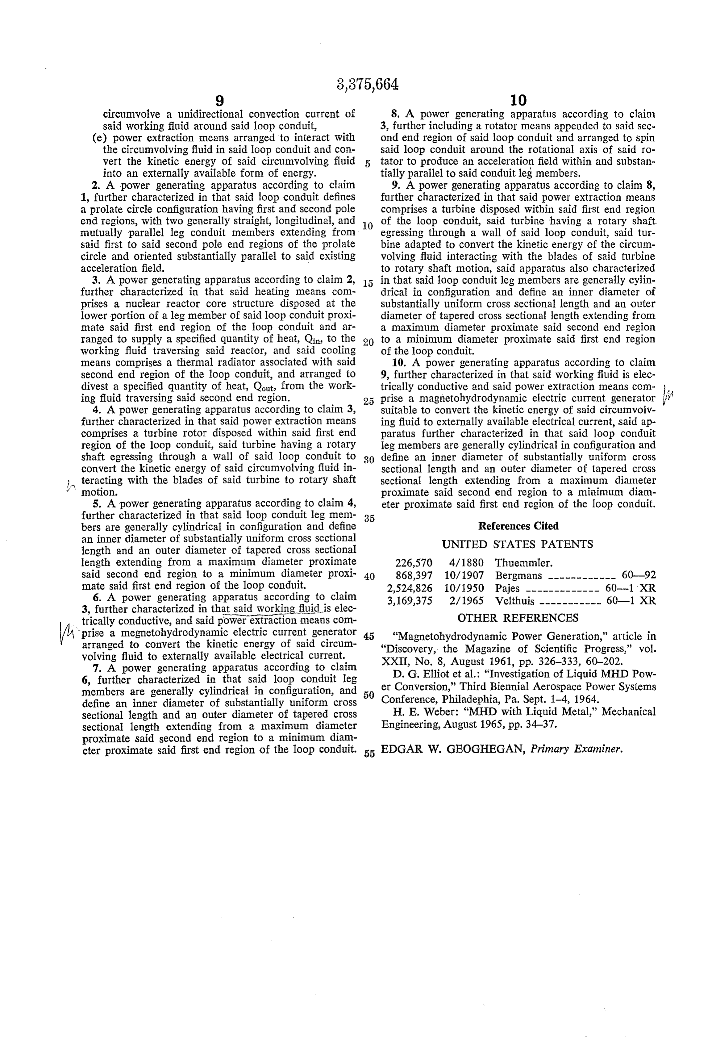
circumvolve a unidirectional convection current of 8. A power generating apparatus according to claim said working fluid around said loop conduit, 3, further including a rotator means appended to said sec (e) power extraction means arranged to interact with ond end region of said loop conduit and arranged to spin the circumvolving fluid in said loop conduit and con said loop conduit around the rotational axis of said ro vert the kinetic energy of said circumvolving fluid tator to produce an acceleration field within and substan into an externally available form of energy. tially parallel to said conduit leg members. 2. A power generating apparatus according to claim 9. A power generating apparatus according to claim 8, 1, further characterized in that said loop conduit defines further characterized in that said power extraction means a prolate circle configuration having first and second pole comprises a turbine disposed within said first end region end regions, with two generally straight, longitudinal, and O of the loop conduit, said turbine having a rotary shaft mutually parallel leg conduit members extending from egressing through a wall of said loop conduit, said tur said first to said second pole end regions of the prolate bine adapted to convert the kinetic energy of the circum circle and oriented substantially parallel to said existing volving fluid interacting with the blades of said turbine acceleration field. to rotary shaft motion, said apparatus also characterized 3. A power generating apparatus according to claim 2, in that said loop conduit leg members are generally cylin further characterized in that said heating means com drical in configuration and define an inner diameter of prises a nuclear reactor core structure disposed at the substantially uniform cross sectional length and an outer lower portion of a leg member of said loop conduit proxi diameter of tapered cross sectional length extending from mate said first end region of the loop conduit and ar a maximum diameter proximate said second end region ranged to supply a specified quantity of heat, Qin, to the 20 to a minimum diameter proximate said first end region working fluid traversing said reactor, and said cooling of the loop conduit.
means comprises a thermal radiator associated with said 10. A power generating apparatus according to claim second end region of the loop conduit, and arranged to 9, further characterized in that said working fluid is elec divest a specified quantity of heat, Qout, from the Work trically conductive and said power extraction means conn ing fluid traversing said second end region. prise a magnetohydrodynamic electric current generator 4. A power generating apparatus according to claim 3, suitable to convert the kinetic energy of said circumvolv further characterized in that said power extraction means ing fluid to externally available electrical current, said ap comprises a turbine rotor disposed within said first end paratus further characterized in that said loop conduit region of the loop conduit, said turbine having a rotary leg members are generally cylindrical in configuration and shaft egressing through a wall of said loop conduit to 30 define an inner diameter of substantially uniform cross convert the kinetic energy of said circumvolving fluid in sectional length and an outer diameter of tapered cross teracting with the blades of said turbine to rotary shaft sectional length extending from a maximum diameter motion. proximate said second end region to a minimum diam 5. A power generating apparatus according to claim 4, eter proximate said first end region of the loop conduit. further characterized in that said loop conduit leg mem 35 bers are generally cylindrical in configuration and define References Cited an inner diameter of substantially uniform cross Sectional UNITED STATES PATENTS length and an outer diameter of tapered cross sectional length extending from a maximum diameter proximate 226,570 4/1880 Thuemmler.
said second end region to a minimum diameter proxi 40 868,397 10/1907 Bergmans ------------ 60-92 mate said first end region of the loop conduit. 2,524,826 10/1950 Pajes ------------- 60-1 XR 6. A power generating apparatus according to claim 3,169,375 2/1965 Velthuis ----------- 60-1, XR 3, further characterized in that said working fluidis elec willors -"
OTHER REFERENCES
trically conductive, and said power extraction means com prise a megnetohydrodynamic electric current generator 45 "Magnetohydrodynamic Power Generation,' article in arranged to convert the kinetic energy of said circum "Discovery, the Magazine of Scientific Progress,' vol. volving fluid to externally available electrical current.
7. A power generating apparatus according to claim XXII, D. G.
Elliot et al.: "Investigation of Liquid MHD Pow 6, further characterized in that said loop conduit leg er Conversion,” Third Biennial Aerospace Power Systems members are generally cylindrical in configuration, and 50 Conference, Philadephia, Pa. Sept. 1-4, 1964. define an inner diameter of substantially uniform cross sectional length and an outer diameter of tapered cross H. E. Weber: “MHD with Liquid Metal,” Mechanical sectional length extending from a maximum diameter Engineering, August 1965, pp. 34–37. proximate said second end region to a minimum diam eter proximate said first end region of the loop conduit. 55 EDGAR W. GEOGHEGAN, Primary Examiner.
Provenance
- Collection
- Cited prior art
- Original PDF
- patentimages.storage.googleapis.com →
- Filed
- 1966-08-02
- Pages
- 6
- Method
- pdftotext (the PDF's own text layer) + pdftoppm 300dpi page scans
- Source
- Google Patents bibliographic record
- Granted
- 1968-04-02
- Inventors
- Jr William M Wells; Atomic Energy Commission Usa
- Transcribed from
- patentimages.storage.googleapis.com →