patent · US3443129
Vapor-liquid cycle mhd power conversion
6 May 1969
Page 1
Drawing sheet — no readable text.
Page 2
Drawing sheet — no readable text.
Page 3
Drawing sheet — no readable text.
Page 4
United States Patent Office 3,443,129 Patented May 6, 1969
condensed or gaseous form and the conductive liquid is 3,443,129 at a temperature high enough so that, when mixed, WAPOR-LIQUID CYCLE MHD POWER thermodynamic fluid forms bubbles, which expand and
CONVERSION
Andrew G. Hammitt, Spring Lake, N.J., assignor to TRW move through the common tube to the other end of the Inc., Redondo Beach, Calif., a corporation of Ohio tube to a separator where the vapor is then separated Filed Mar. 17, 1966, Ser. No. 535,380 from the liquid. These bubbles form a simple means for Int, CI. H02k 45/00, G21d 7/02 coupling the thermodynamic fluid and the conductive liq U.S. C. 30- 4 Claims luid medium and serve to pump or drive the conductive liquid against a force field by dragging the liquid along
O by viscous forces. As the liquid returns to the mixer, as
ABSTRACT OF THE DISCLOSURE aforesaid, the conducting liquid is driven by this force field The working fluid of the MHD is a conductive liquid through the magnetic field of the MHD generator to gen propelled by a vapor portion of the liquid or the vapor erate the electrical energy. At the same time, the vapor of a second liquid. separated from the liquid in the separator end is passed through a condenser to form a condensate which is re turned by this force field to the mixer.
This invention relates to magnetohydrodynamic In one embodiment of this invention a gravity force (MHD) systems for thermal electric power conversion field is used as the force field referred to above. The and it is a general object of this invention to provide a 20 common tube, sometimes called a bubble tube, is disposed MHD hermal electric power conversion system by the vertically so that the fluids in the mixer, being lower than use of fluids at low fluid velocities and without mechani the separator, are at a higher pressure due to the gravity cal moving parts. head in the loop than the liquid and vapor at the higher separator. In this manner, the bubbles pump the liquid
It is recognized that MHD systems utilizing fluids for against thermal electric power conversion have been proposed. the gravity in the bubble tube to a higher level The most common proposed system includes a jet mixing expendedthus increasing the liquid's potential energy which is then system in which one fluid is driven by another by a jet through thebyMHD allowing the liquid to return to the mixer generator by the force of gravity.
mixing momentum exchange system with the driven fluid It can be appreciated that using the expansion of the directed through an MHD generator to generate electrical bubbles against gravity is highly efficient and that the energy. Such a system, for example, will utilize a liquid 30 System mercury loop driven by a mercury vapor jet. This system is kept simple by the utilization of the gravity has disadvantages for MHD power conversion because of force to obtain an expansion and compression cycle of the vapor medium and the liquid medium. The selection its inefficiency due to mixing losses. By way of explana of the fluids may be chosen to allow a suitable thermo tion, in such a system because the liquid loop must be dynamic cycle in conjunction with the pressure limita kept at low velocities to keep the friction reasonably low, tions imposed by the strength of the gravity field. Thus, and the velocity of the vapor jet must be kept high to dependent upon the mediums selected for the pressure provide a reasonable thermodynamic cycle with a rela tively high energy release per unit mass of fluid, the mix and temperature ranges desired, this system may be used ing losses are high and low efficiency will result. in a number of applications, such as simple unattended Another known system utilizing two fluids embodies a 40 small sized power plants or, for example, in central power stations where the simplicity of the system allows higher loop of driven liquid medium and a loop of driving vapor temperatures to be obtained than may be obtained in medium; the latter for imparting high velocity to the more complicated Systems having mechanical moving driven liquid. In this system, the driven liquid is heated parts.
and mixed with the condensed vapor medium at a tem In space requirements where there may be insufficient perature which will vaporize the condensate. This mix 45 gravity force to provide the force field or whenever this ture is then expanded through a nozzle in which high gravity force field is inadequate another embodiment may Velocity is imparted to the liquid. Thereafter, the driven be utilized. In the second disclosed embodiment an MHD liquid and vapor are separated while still at high velocity force and the high velocity driven liquid is directed through an field is used. A high pressure zone at the mixing MHD generator to generate electrical energy. At the 50 end of the bubble tube and a low pressure zone at the same time, the separated vapor medium is condensed separation end of the bubble tube may be created by pro and returned to a point where it will be mixed again with viding two MHD pumps in the liquid loops which pump the heated driven liquid to begin the cycle again. the liquid from the separator toward the mixer and an This latter system, while having no moving parts, is MHD generator in the leg which expands the mixture quite complex and has many inherent problems because 55 driventhis from mixer to the separator. The MHD pumps are by a portion of the electrical energy converted by of the velocity of the fluid at which the system operates.
For example, such a system requires special equipment to the MHD generator, which in this embodiment, is lo Separate the vapor from the high velocity driven liquid cated between the mixer and the separator so as to be medium; there are also high losses involved in such a driven by the bubbling vapor-conductive liquid mixture. separation, and the friction losses of the high velocity 60 Itthisis second contemplated also that in certain use applications of disclosed embodiment a cyclonic separator liquid are high. would be utilized.
The present invention simplifies MHD electric power Another version of either of the embodiments of this generator conversion systems and thus overcomes the problems of the above-known systems. The system which invention contemplates the use of a plurality of fine or smaller tubes incorporated in the bubble tube so that the comprises this invention energizes a loop of driving vapor 65 tube is broken up into fine passages and the flow there medium, sometimes called the thermodynamic fluid, and through comprises slugs of liquid separated by bub a loop of driven liquid medium, sometimes called the conductive liquid, which are mixed at one end of a leg bles. This version would utilize the pumping ability of or tube common between the two loops. Two separate the bubbles by percolation more efficiently, and if de substances may be used for one substance for both pur 70 sired, could form a type of pulsating D.C. current, where poses. At the mixing end of the tube, or mixer as it is the application of such current would be desirable. In sometimes called, the thermodynamic fluid is either in order to extract the electrical energy form the pulsating
Page 5
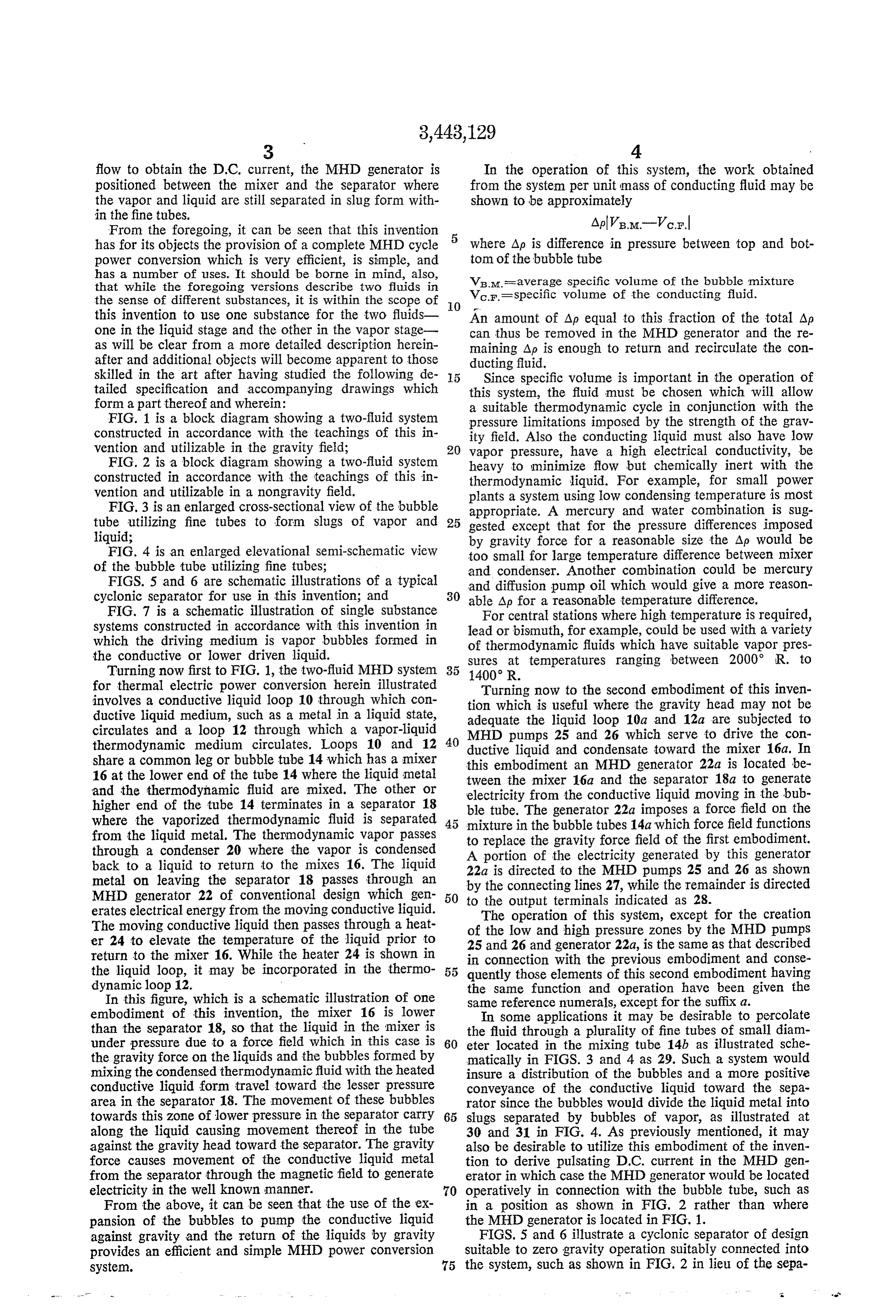
flow to obtain the D.C. current, the MHD generator is In the operation of this system, the work obtained positioned between the mixer and the separator where from the System per unit mass of conducting fluid may be the vapor and liquid are still separated in slug form with shown to be approximately in the fine tubes.
From the foregoing, it can be seen that this invention has for its objects the provision of a complete MHD cycle 5 where Ap is difference in pressure between top and bot power conversion which is very efficient, is simple, and tom of the bubble tube has a number of uses. It should be borne in mind, also, VB.M. = average specific volume of the bubble mixture that while the foregoing versions describe two fluids in Vc.F.=specific volume of the conducting fluid. the sense of different substances, it is within the scope of O this invention to use one substance for the two fluids one in the liquid stage and the other in the vapor stage An amount of Ap equal to this fraction of the total Ap can thus be removed in the MHD generator and the re as will be clear from a more detailed description herein maining Ap is enough to return and recirculate the con after and additional objects will become apparent to those ducting fluid.
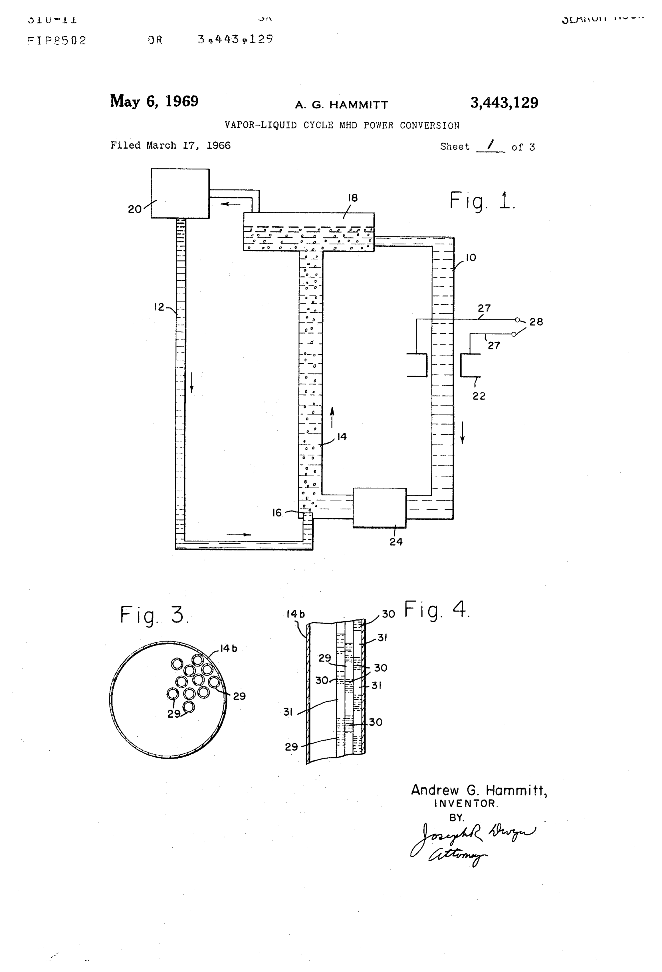
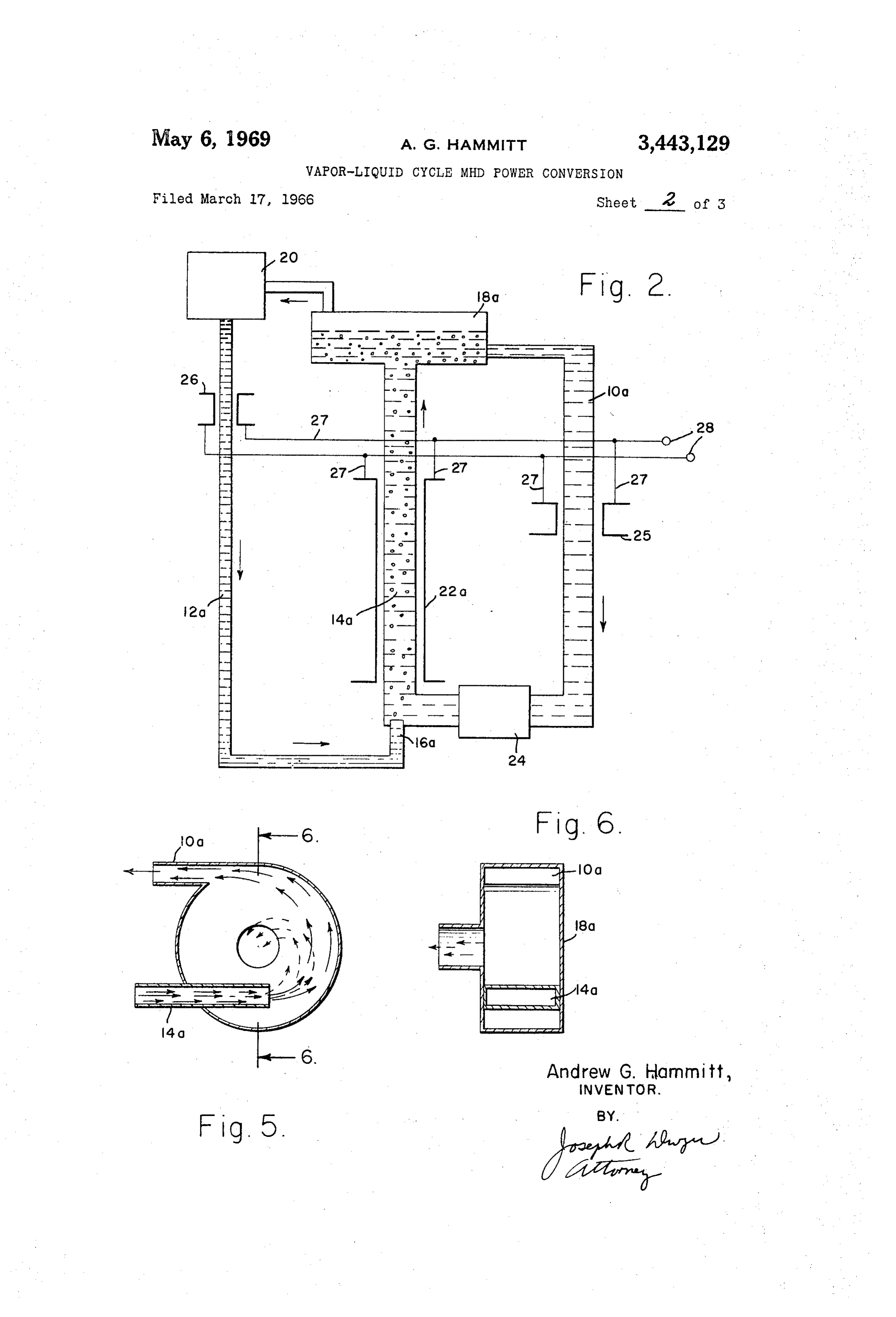
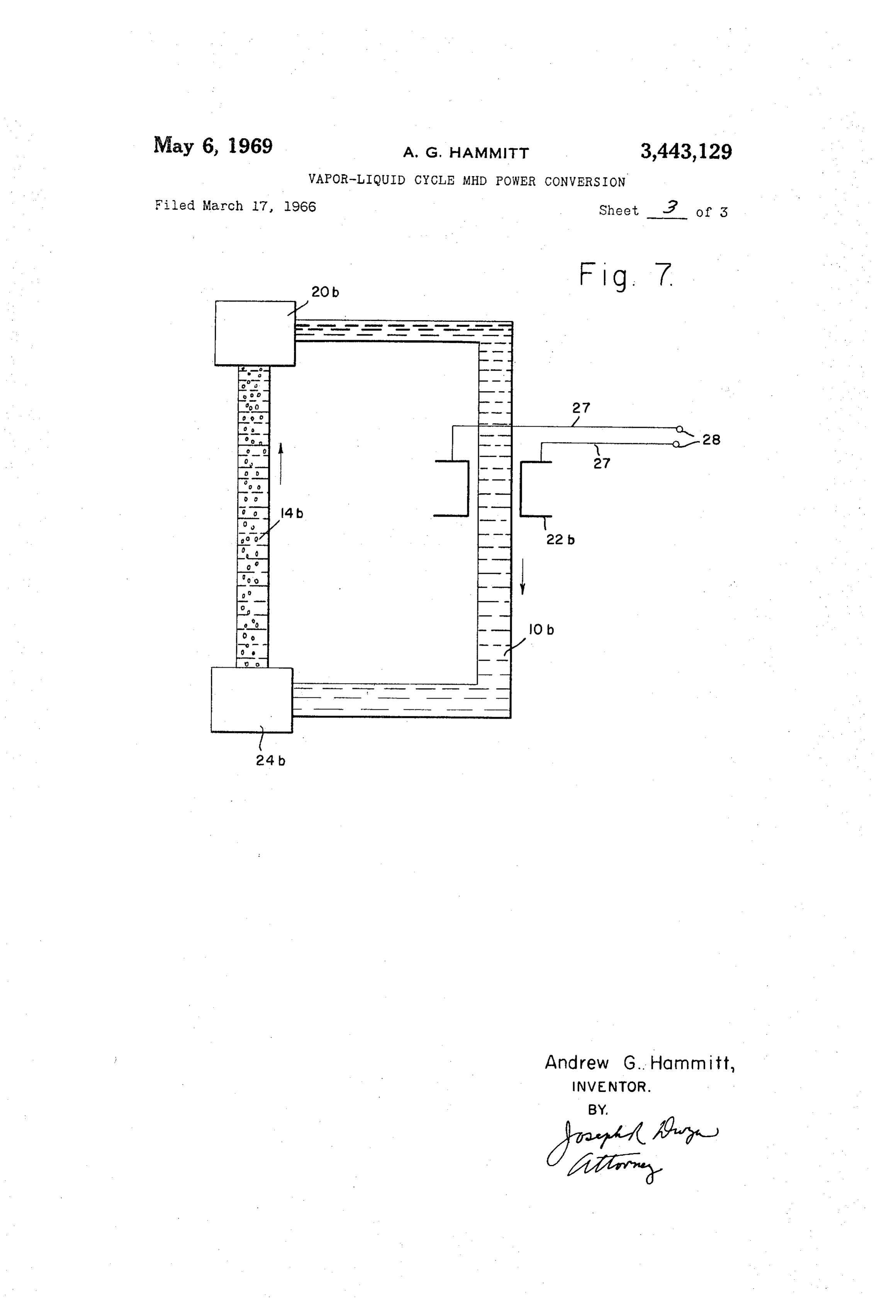
skilled in the art after having studied the following de 5 Since specific volume is important in the operation of tailed specification and accompanying drawings which this system, the fluid must be chosen which will allow form a part thereof and wherein: a suitable thermodynamic cycle in conjunction with the FIG. 1 is a block diagram showing a two-fluid system pressure limitations imposed by the strength of the grav constructed in accordance with the teachings of this in ity field. Also the conducting liquid must also have low vention and utilizable in the gravity field; 20 vapor pressure, have a high electrical conductivity, be FIG. 2 is a block diagram showing a two-fluid system heavy to minimize flow but chemically inert with the constructed in accordance with the teachings of this in thermodynamic liquid. For example, for small power vention and utilizable in a nongravity field. plants a system using low condensing temperature is most FIG. 3 is an enlarged cross-sectional view of the bubble appropriate. A mercury and water combination is sug tube utilizing fine tubes to form slugs of vapor and 25 gested except that for the pressure differences imposed liquid; by gravity force for a reasonable size the Ap would be FIG. 4 is an enlarged elevational semi-schematic view too small for large temperature difference between mixer of the bubble tube utilizing fine tubes; and condenser. Another combination could be mercury FIGS. 5 and 6 are schematic illustrations of a typical and diffusion pump oil which would give a more reason cyclonic separator for use in this invention; and 30 able Ap for a reasonable temperature difference. FIG. 7 is a schematic illustration of single substance For central stations where high temperature is required, systems constructed in accordance with this invention in lead or bismuth, for example, could be used with a variety which the driving medium is vapor bubbles formed in of thermodynamic fluids which have suitable vapor pres the conductive or lower driven liquid. sures at temperatures ranging between 2000 R. to Turning now first to FIG. 1, the two-fluid MHD system 35
for thermal electric power conversion herein illustrated Turning now to the second embodiment of this inven involves a conductive liquid loop 10 through which con tion which is useful where the gravity head may not be ductive liquid medium, such as a metal in a liquid state, adequate the liquid loop 10a and 12a are subjected to circulates and a loop 12 through which a vapor-liquid thermodynamic medium circulates. Loops 10 and 12 40 ductivepumps
MHD liquid 25 and 26 which serve to drive the con and condensate toward the mixer 16a. In share a common leg or bubble tube 14 which has a mixer this embodiment an MHD generator 22a is located be 16 at the lower end of the tube 14 where the liquid metal tween the mixer 16a and the separator 18a to generate and the thermodynamic fluid are mixed. The other or electricity from the conductive liquid moving in the bub higher end of the tube 14 terminates in a separator 18 where the vaporized thermodynamic fluid is separated ble tube. The generator 22a imposes a force field on the mixture in the bubble tubes 14a which force field functions from the liquid metal. The thermodynamic vapor passes to replace the gravity force field of the first embodiment. through a condenser 20 where the vapor is condensed A portion of the electricity generated by this generator back to a liquid to return to the mixes 16. The liquid 22a is directed to the MHD pumps 25 and 26 as shown metal on leaving the separator 18 passes through an by the connecting lines 27, while the remainder is directed MHD generator 22 of conventional design which gen 50 to the output terminals indicated as 28. erates electrical energy from the moving conductive liquid. The operation of this system, except for the creation The moving conductive liquid then passes through a heat of the low and high pressure zones by the MHD pumps er 24 to elevate the temperature of the liquid prior to 25 and 26 and generator 22a, is the same as that described return to the mixer 16. While the heater 24 is shown in in connection with the previous embodiment and conse the liquid loop, it may be incorporated in the thermo 55 quently those elements of this second embodiment having dynamic loop 12. the same function and operation have been given the In this figure, which is a schematic illustration of one same reference numerals, except for the suffix a. embodiment of this invention, the mixer 16 is lower In some applications it may be desirable to percolate than the separator 18, so that the liquid in the mixer is the fluid through a plurality of fine tubes of small diam under pressure due to a force field which in this case is 60 eter located in the mixing tube 14b as illustrated sche the gravity force on the liquids and the bubbles formed by matically in FIGS. 3 and 4 as 29. Such a system would mixing the condensed thermodynamic fluid with the heated insure a distribution of the bubbles and a more positive conductive liquid form travel toward the lesser pressure conveyance of the conductive liquid toward the sepa area in the separator 18. The movement of these bubbles rator since the bubbles would divide the liquid metal into towards this zone of lower pressure in the separator carry 65 slugs separated by bubbles of vapor, as illustrated at along the liquid causing movement thereof in the tube 30 and 31 in FIG. 4. As previously mentioned, it may against the gravity head toward the separator. The gravity also be desirable to utilize this embodiment of the inven force causes movement of the conductive liquid metal tion to derive pulsating D.C. current in the MHD gen from the separator through the magnetic field to generate erator in which case the MHD generator would be located electricity in the well known manner. 70 operatively in connection with the bubble tube, such as From the above, it can be seen that the use of the ex in a position as shown in FIG. 2 rather than where pansion of the bubbles to pump the conductive liquid the MHD generator is located in FIG. 1.
against gravity and the return of the liquids by gravity FIGS. 5 and 6 illustrate a cyclonic separator of design provides an efficient and simple MHD power conversion suitable to zero gravity operation suitably connected into System. 75 the system, such as shown in FIG. 2 in lieu of the sepa
Page 6
rator 18a, as shown therein. This cyclonic separator would means for condensing the propelling medium before separate the liquid and the vapor by centrifugal effect and the medium is mixed with said conductive means; would be required where gravity is not available to use a first closed system for circulating a conductive liquid to operate the separation system such as illustrated in medium;
FIG. 2. a second closed system for circulating the propelling Since the connection of the cyclonic separator is located medium, said circulating systems having a common in the drawings with appropriate reference numerals illus conduit for mixing said mediums; trating the legs of the loops, no further description is thermal energy supplying means for vaporizing said needed herein. propelling medium at one end of said common As previously mentioned, while the foregoing discussed O conduits;
the inventive concept in connection with a two-fluid sys separator means being located at the other end of said tem in which the driving and driven mediums were dif common conduit for returning said mediums to their ferent substances, the driven medium can be of the same respective systems, said vaporized propelling medium Substance except in the vapor stage. FIG. 7 illustrates carrying said conductive liquid medium along as it an apparatus for producing electrical energy in which the 15 flows toward said separator; means for applying thermal energy 24b is located so as means for creating a Zone of high pressure, said means to form bubbles at the zone of higher pressure of leg being formed by having said separator higher than 14b with a condenser 20b located at the opposite end Said one end of said common conduit so that said of leg 14b, so that the bubbles will drive the liquid mediums flow against gravity toward said separator from one end of the leg to the other. When condensed 20 to return to said one end by gravity. in condenser 20b, the driven liquid continues on to flow 2. An apparatus for producing electrical energy com through leg 10b to generate electricity in MHD generator prising:
22b. an electrically conductive medium; It can be appreciated that the operation of the appa a propelling medium comprising vapor; ratus shown in FIG. 7 is comparable to the devices pre 25 means for mixing said mediums whereby said vapor viously described in FIGS. 1-6 and for that reason the travels through said liquid medium against a force same reference numbers were used to identify compo field and moves the liquid medium of said mixture nents having the same function and operation (except therewith;
for the suffix b) and while FIG. 7 illustrates a gravity means for establishing a magnetic field in the region system, the apparatus can be used in a nongravity environ 30 of said conductive medium to produce electrical ment by the use of an MHD pump used in a manner energy;
described in the previous figures. means for separating said mediums; From the foregoing it can be seen that the advantages means for defining a flow path for each of said mediums of this invention lie in the fact that the velocity of the from said separating means to said mixing means; fluids operating in the system is not within any par 35 means for condensing the propelling medium before ticular range; that the problems of separation of gas the medium is mixed with said conductive means; and liquid at high velocity have been eliminated; con a first closed system for circulating a conductive liquid version of thermal energy to potential energy rather than medium;
kinetic energy before conversion to electricity simplifies a second closed system for circulating the propelling the present system; that the friction losses attendant in 40 medium, said circulating systems have a common high velocity liquid systems have been eliminated; and conduit for mixing said mediums, said second closed that the number of parts necessary to operate a system System having a second loop containing a second at high velocity have been obviously reduced. While two liquid medium;
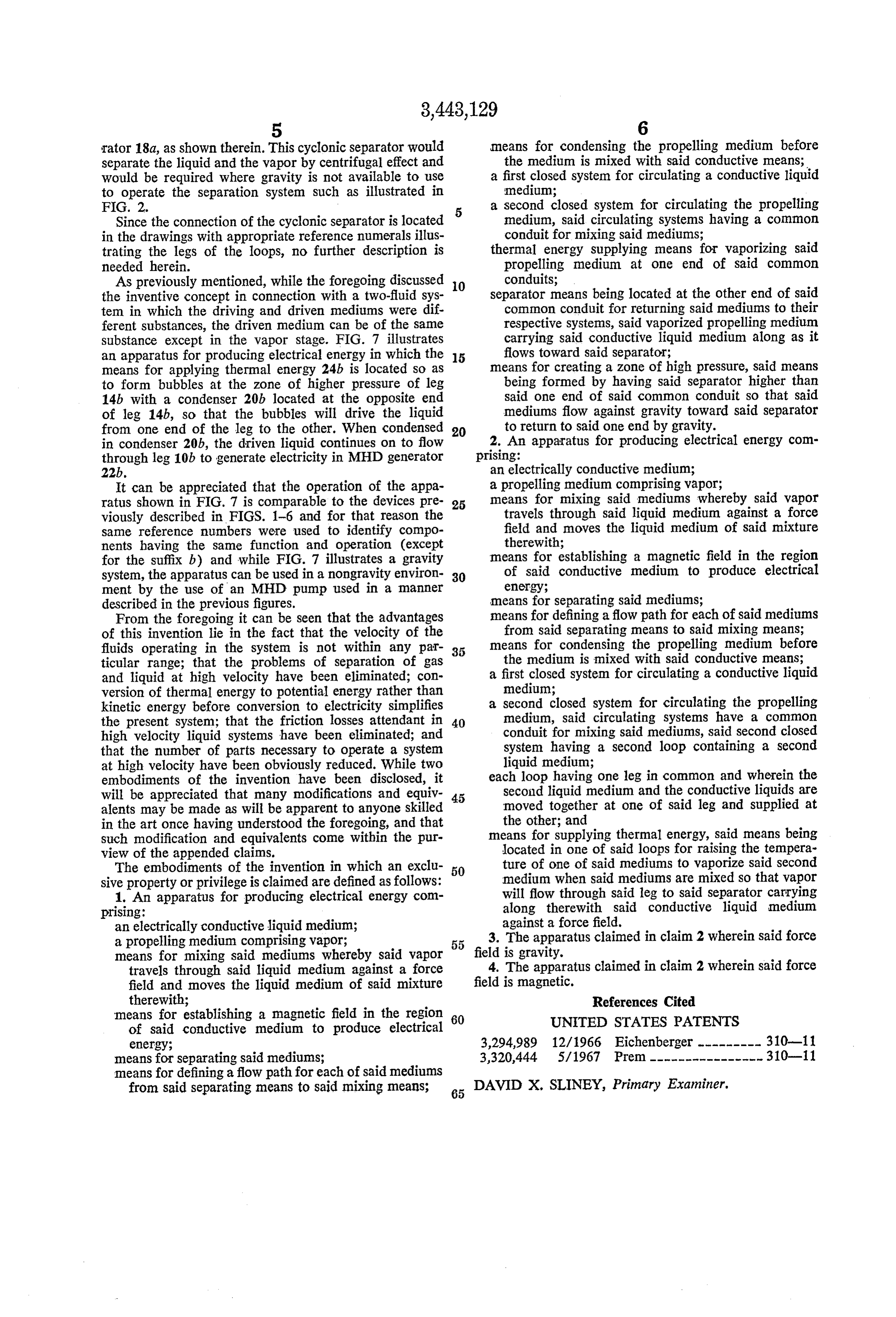
embodiments of the invention have been disclosed, it each loop having one leg in common and wherein the will be appreciated that many modifications and equiv 45 second liquid medium and the conductive liquids are alents may be made as will be apparent to anyone skilled moved together at one of said leg and supplied at in the art once having understood the foregoing, and that the other; and such modification and equivalents come within the pur means for supplying thermal energy, said means being view of the appended claims. located in one of said loops for raising the tempera The embodiments of the invention in which an exclu 50 ture of one of said mediums to vaporize said second sive property or privilege is claimed are defined as follows: medium when said mediums are mixed so that vapor 1. An apparatus for producing electrical energy com will flow through said leg to said separator carrying prising: along therewith said conductive liquid medium an electrically conductive liquid medium; against a force field.
a propelling medium comprising vapor; 55 3. The apparatus claimed in claim 2 wherein said force means for mixing said mediums whereby said vapor field is gravity.
travels through said liquid medium against a force 4. The apparatus claimed in claim 2 wherein said force field and moves the liquid medium of said mixture field is magnetic.
therewith; References Cited means for establishing a magnetic field in the region 60 UNITED STATES PATENTS of said conductive medium to produce electrical energy; 3,294,989 12/1966 Eichenberger --------- 310-11 means for separating said mediums; 3,320,444 5/1967 Prem ---------------- 310-11 means for defining a flow path for each of said mediums from said separating means to said mixing means; 65 DAVID X, SLINEY, Primary Examiner.
Provenance
- Collection
- Cited prior art
- Original PDF
- patentimages.storage.googleapis.com →
- Filed
- 1966-03-17
- Pages
- 6
- Method
- pdftotext (the PDF's own text layer) + pdftoppm 300dpi page scans
- Source
- Google Patents bibliographic record
- Granted
- 1969-05-06
- Inventors
- Andrew G Hammitt; TRW Inc
- Transcribed from
- patentimages.storage.googleapis.com →