patent · US3999089
Non-pollutant fuel generator and fuel burner with a non-pollutant exhaust and supplementary D.C. generator
21 December 1976
Page 1 — bibliographic record
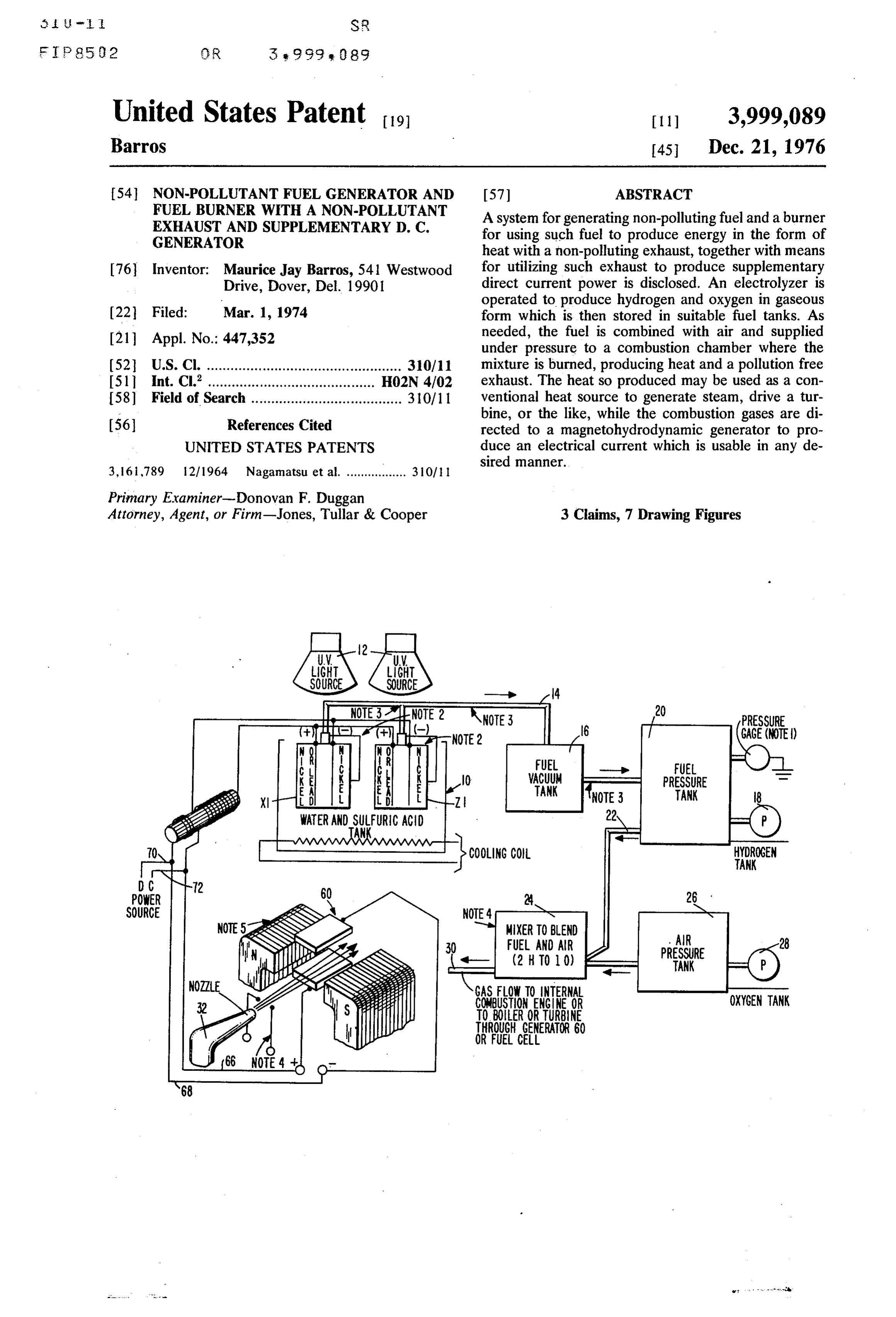
United States Patent to 11) 3,999,089 Barros 45 Dec. 21, 1976 54. NON-POLLUTANT FUEL GENERATOR AND 57 ABSTRACT FUEL BURNER WITH A NON-POLLUTANT A system for generating non-polluting fuel and a burner EXHAUST AND SUPPLEMENTARY D. C. for using such fuel to produce energy in the form of GENERATOR heat with a non-polluting exhaust, together with means 76 Inventor: Maurice Jay Barros, 541 Westwood for utilizing such exhaust to produce supplementary Drive, Dover, Del, 19901 direct current power is disclosed. An electrolyzer is operated to produce hydrogen and oxygen in gaseous (22 Filed: Mar. 1, 1974 form which is then stored in suitable fuel tanks. As 21 Appl. No.: 447,352 needed, the fuel is combined with air and supplied under pressure to a combustion chamber where the 52 U.S. Cl. ................................................. 310/11 mixture is burned, producing heat and a pollution free I5ll Int. Cl”.......................................... H02N 4/02 exhaust. The heat so produced may be used as a con 58) Field of Search ...................................... 310/11 ventional heat source to generate steam, drive a tur (56) References Cited bine, or the like, while the combustion gases are di rected to a magnetohydrodynamic generator to pro
UNITED STATES PATENTS duce an electrical current which is usable in any de sired manner.
Primary Examiner-Donovan F. Duggan
Attorney, Agent, or Firm-Jones, Tullar & Cooper 3 Claims, 7 Drawing Figures
NOTE2 GAGE (NOTE)
HYDROGEN
ANK
MIXER TO BLEND
PRESSURE
ANK
GAS FLOW TO INTERNAL OXYGEN TANK
USTION ENGINE OR
BOER ORTURBINE
Page 2
Drawing sheet — no readable text.
Page 3
Drawing sheet — no readable text.
Page 4
Drawing sheet — no readable text.
Page 5
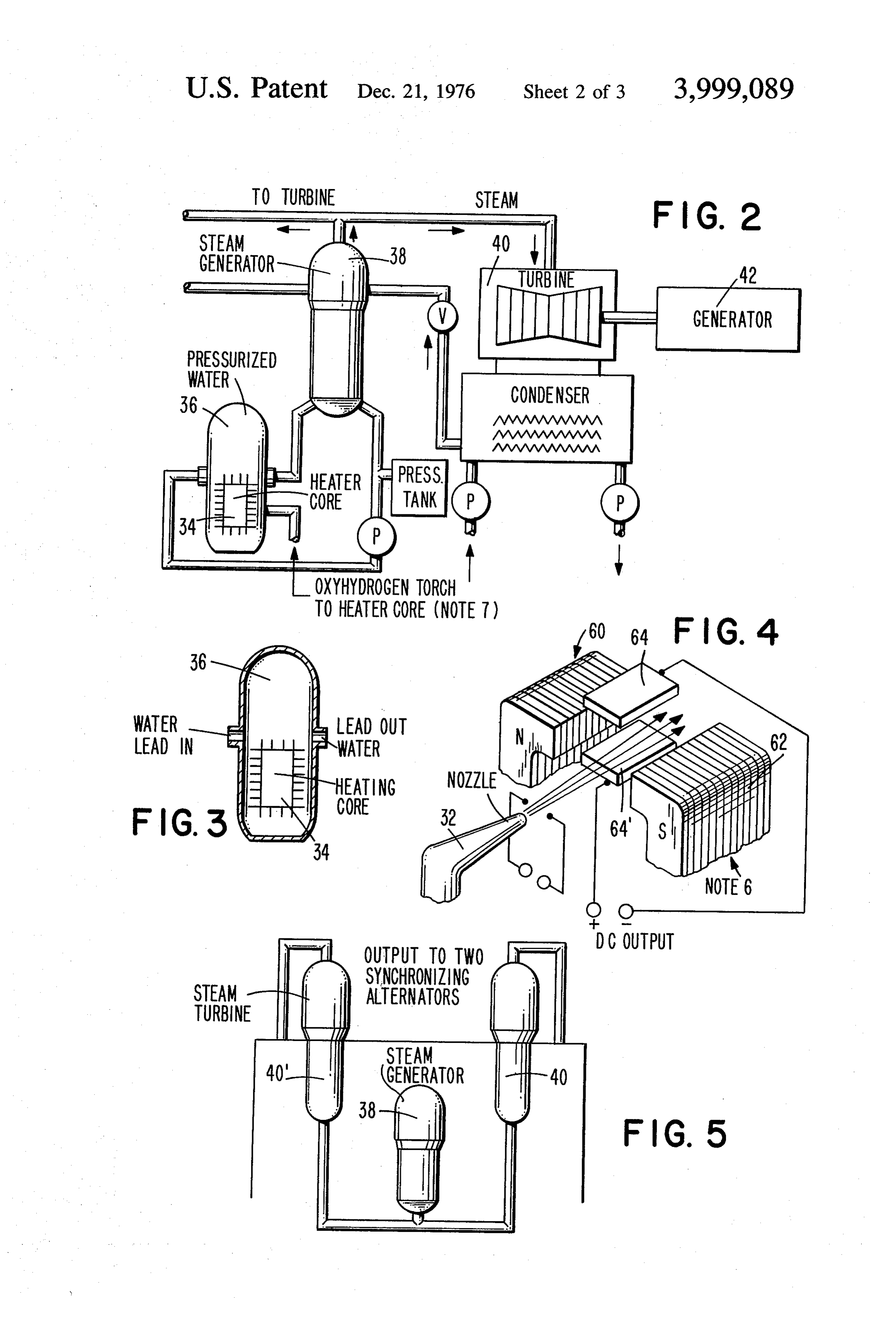
FIG. 2 is a diagrammatic illustration of a steam power
NON-POLLUTANT FUEL GENERATOR AND FUEL system utilizing the fuel generated in the system of FIG. BURNER WITH A NON-POLLUTANT EXHAUST 1;
AND SUPPLEMENTARY D. C. GENERATOR FIG.3 is a diagrammatic illustration of a heating core BACKGROUND OF THE INVENTION usable in the arrangement of FIG. 2; FIG. 4 is a diagrammatic illustration of an MHD
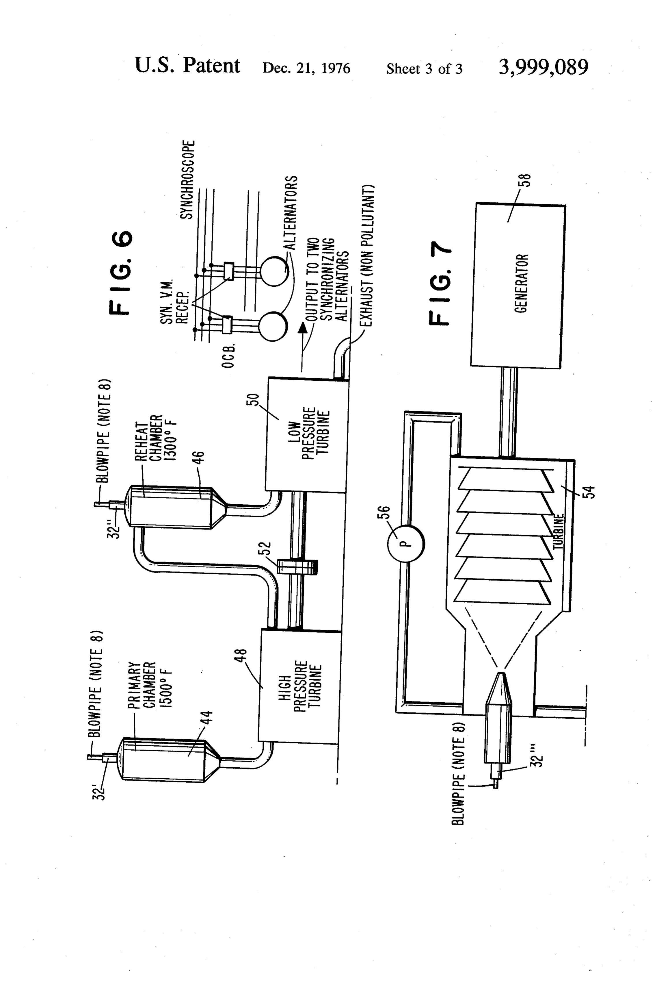
The present invention relates, in general, to a system generator usable in the system of FIG. 1; for producing and using non-polluting fuel for the pro FIG. 5 is a diagrammatic illustration of an alternate duction of heat and electricity. The basic fuel is hydro form of power producing system;
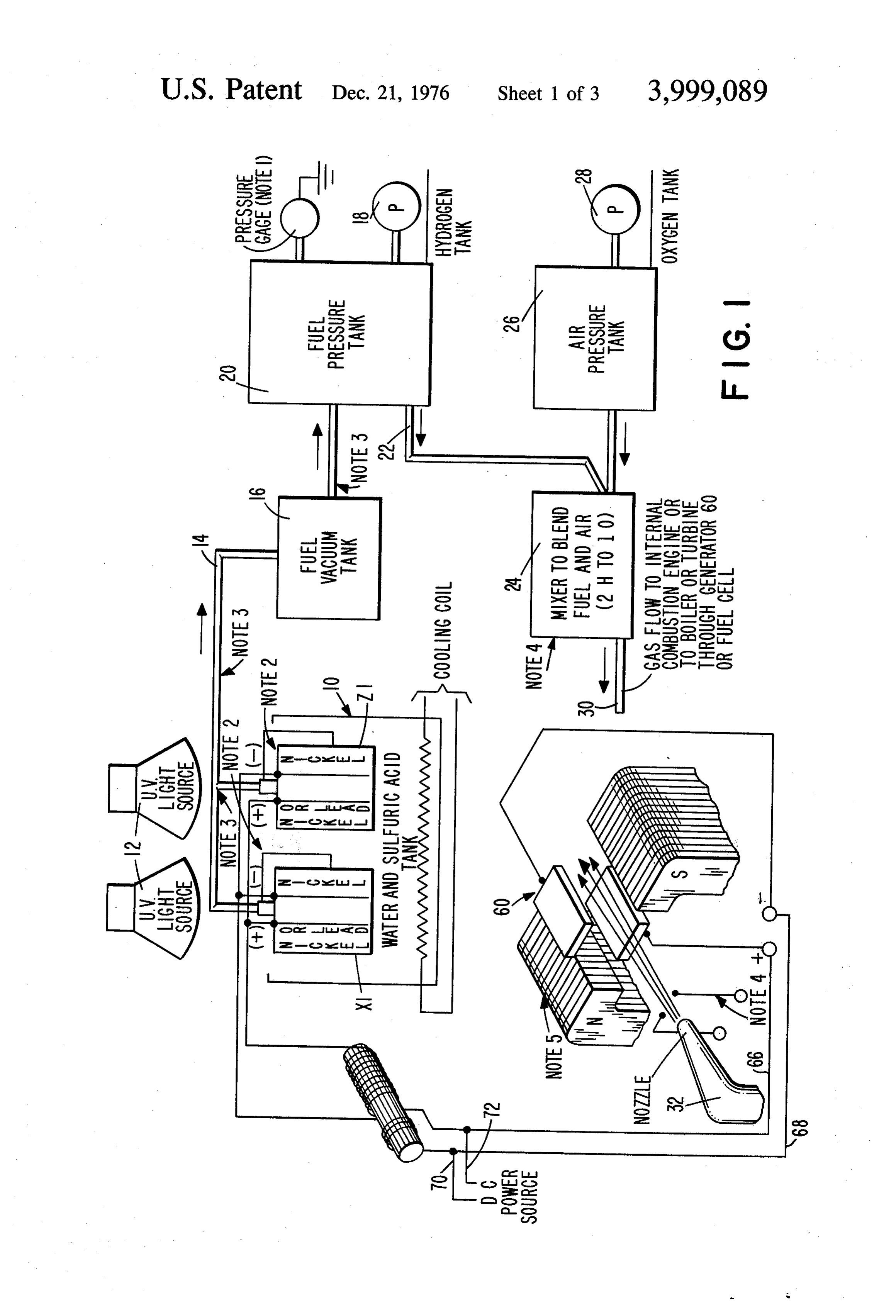
gen and any other gas released through the electrolysis 10 FIG. 6 is a diagrammatic illustration of a turbine of water. In fresh water, using sulfuric acid as a catalyst, power generator using the fuel produced by the system the fuel would be hydrogen and oxygen. This fuel may of FIG. 1; and be burned in any heating core with the combustion FIG. 7 is a modified form of the system of FIG. 6. products being used not only to produce heat, but to DETALED DESCRIPTION generate electricity through the use of a magnetohy 15 drodynamic generator. Such a system operates without For clarity, certain legends have been omitted from polluting the atmosphere with its exhausts and provides the drawings, where indicated by "notes', and refer heat and both mechanical and electrical power for ence may be had to the following for an explanation of virtually any use. Without limiting the potential uses of such notes:
the energy so generated, the heat and power produced 20 Note 1: Pressure gage regulates electricity to generat by the non-polluting system of the present invention ing tank 10.
may find use in the following areas. Note 2: Water gage provided to release gas at set 1. Use in electric generators by Utilities. level to keep pressure out of generating tank 10. 2. Use in apartment heating plants. Note 3: Pressure safety stop vacuum gage (-pressure 3. Use in home heating units. 25 to tank 16) provided.
4. Use in ships with salt water. Note 4: Gas ionized by arc under pressure. Use elec a. Note, electrolysis of saltwater will supply hydro tric arc for ultraviolet light source at flame. Use gen and chlorine which will burn and produce tungsten electrodes.
equal. Note 5: To regulate temperature increase or decrease 5. Use with Internal-Combustion Engine. 30 pressure to 300 pounds per square inch to 7,000°F. a. Feed ration 2 LBH - 10). Also, up to 4 H. to 1 o. straight fuel will increase b. Exhaust gas water vapor non-pollutant. temperature to 5,000 F burning hydrogen with 6. Use in small boats I. C. Engine oxygen only; regulate amperes to arc. Also could 7. Use in automobiles I. C. Engine be done by using air pressure tank 26 and sending SUMMARY OF THE INVENTION 35 only negative (-) charge to nickel cathode in sepa Briefly, the invention discloses a method and appara rate cell X1 and positive (+) to lead anode in sepa tus for producing a fuel and for using that fuel to gener rate cell Z1, or not using air from atmosphere; add ate heat and electrical energy. The fuel is produced in extra vacuum tank for oxygen. an electrolyzer, in the preferred embodiment, with a 40 catalystRecycling
program. Exhaust over a nickel
The use of Fisher Tropsch Syn solution of water and sulfuric acid producing hydrogen thesis by adding hydrogen at this point produces gas which may be stored in a suitable tank for later use. liquid hydrocarbons or methane, synthetic gaso The hydrogen gas is a safe and non-polluting fuel which lines which are less toxic. may be shipped in large quantities with a high degree of safety. The hydrogen gas, together with any other com 45 gen 7:fuelOxyhydrogen
Note ignited by an torch uses hydrogen and oxy electric arc. A nickel ignition bustible gas released through the electrolysis of water, chamber is used. For utraviolet light, arc electrodes is pressurized and may then be supplied to a suitable are tungsten. Ignition chamber temperature: 700 burner associated with a conventional heating core C. To regulate temperature in heating core, vary whereby the heat of combustion may be used in the generation of steam for use in driving turbines, for 50 mixture ofoffuel pressure fuel to 300 lbs/in to 7,000 F.; vary
heating uses and the like. F; vary amperes to arc to 7,000 F. Exhaust is non Combustion of the fuel mixture is accomplished by polluting.
means of an electric arc, producing a very high temper Note 8: Oxyhydrogen ignited by electric arc. ature ionized gas which is directed through the mag Referring now to FIG. 1, there is illustrated at 10 an netic field of a magnetohydrodynamic (MHD) genera 55 electrolyzer tor immediately before or immediately after passing produce thewhich is utilized in the present invention to non-polluting fuel which is to be burned.
through the heating core. The MHD generator pro duces a direct current output which may be used for The electrolyzer is of conventional construction having one or more cathodes of nickel and anodes of a suitable any desired purpose.
material such as nickel or lead to which a source of
E. BRIEF DESCRIPTION OF DRAWINGS 60 direct current is supplied. The electrolyzer contains The foregoing and additional objects, features and water and a suitable electrolyte such as sulfuric acid to advantages of the invention will become apparent to produce oxygen and hydrogen. If desired, a source of those of ordinary skill in the art from a consideration of ultraviolet light such as lamps 12 may be used in con the following detailed description, taken in conjunction junction with the electrolytic tank 10 to assist in the with the accompanying drawings, in which 65 generation of oxygen and hydrogen. FIG. 1 is a diagrammatic illustration of a system for This is a simple application of fission and fusion. generating and utilizing non-polluting fuel in accor Commerical electrolyzers typically operate at efficien dance with the present invention; cies of about 60 to 70 percent-although some high
Page 6
pressure prototypes may reach 85 percent. Future de In all of the systems, additional electrical power can velopments may increse this efficiency by using waste be obtained from the operation of the nozzle, or blow heat from the combustion process, thus be used to free pipe, 32 through the provision of a magnetohydrody the hydrogen and oxygen. namic generator generally indicated at 60 in FIGS. 1 Compared to the present fossil fuel burners which and 4. By reason of its ignition, by means of an electri give back no fuel, only pollutants, my invention using cal arc, the combustion products from nozzle 32 com these applications can be a great benefit for all man prise a high temperature stream of ionized gas. kind. The actual flame or stream of ionized gas is directed There is some concern-often called the "Hinden at high speed between the poles of a magnet and also burg Syndrome" about the safety of hydrogen, but 10 between two electrodes, the resulting electro-magnetic most such fears seem exaggerated noting the large force produces lateral movement of the charged quantities of hydrogen shipped and used both in this carries; ie. a Hall effect between the electrodes thus country and in Europe with a high degree of safety. setting up a potential difference between them. The Have you ever heard of a hydrogen spill? arrangement is shown schematically on FIGS. 1 and 4. The gaseous output from the electrolyzer 10 is sup 15 The magnet is illustrated at 62 and the output elec plied by way of a gas line 14 to a suitable fuel tank 16 trodes at 64 and 64". As is known in the MHD genera which receives and temporarily stores, for example, the tor art, the flow of a hot ionized gas through a magnetic hydrogen produced by unit 10. A pump 18 transfers the field generates an electric potential between electrodes fuel to a pressure tank 20 for storage or transportation 64 and 64", producing a direct current output on lines under pressure. A suitable pressure regulating gauge 66 and 68 (FIG. 1), which output may be used for any (not shown) may be provided to regulate the pressure desired purpose, and in particular may be used to assist of the fuel in tank. 20. in the electrolysis of water for the production of the As required, the gaseous fuel from tank 20 may be fuel used in the present system. Additional electrical supplied under pressure by way of line 22 to a suitable power requirements of the electrolyzer may be ob mixing chamber 24 where the fuel is mixed with air and 25 tained from a source of direct current by way of lines 70 and 72. This method of generating electricity has the oxygen produced by the electrolyzer 10 which is the stored in an air supply tank 24 which is also pressur can advantage that it lends itself to large plant sizes and ized, as by means of pump 28. The resulting air and fuel atingbestations.
integrated into the conventional thermal gener
No complicated moving parts exposed to mixture is then supplied by way of a fuel line 30 for utilization in an internal combustion engine, a heating 30 high nited temperatures are required. The fuel must be ig by an electric arc using tungsten electrodes to core, or the like. In a preferred form of the invention, produce the air-fuel mixture is supplied to a burning nozzle 32 moleculesanbecome Ultra-Violet light source after the hydrogen which acts as an oxyhydrogen torch. The fuel mixture is by passing a nickelconverted catalyst.
into more reactive atoms
At this point it would be ignited by means of an electric arc, with the resulting 35 helpful to quote Pashen' law. "The flame being directed to a heating core 34 (FIGS. 2 and between electrodes in a gas depends onspark the potential length of 3) located in a suitable boiler tank 36. The boiler con the spark gap and the pressure of the gas in such a way tains water under high pressure which is then heated to that it is directly proportional to the mass of gas be a suitable temperature, which may be as high as 700 tween the two electrodes; ie. the sparking potential is a centigrade, by the combustion of the fuel and air mix 40 function of the pressure times the density of the gas.” ture. The heated water is circulated through a heat exchanger in a steam generator 38, with the steam and to maintaintheit temperature
being utilized in conventional manner to drive a suit sure of the fuel is controlled to acentrigrade,
maximum of 300lbs.
able turbine 40, which in turn may drive an electrical generator 42. As illustrated in FIG. 5, the steam gener 45 per square foot. In addition, control is obtained by regulating the mixture of the fuel and air, and by con ator 38 may be used to drive a pair of turbine genera trolling the current flow to the arc ignition electrodes. tors 40 and 40' if desired. With maximum current flow, the arc may produce a The combustion products from the nozzle 32, which temperature of up to 7000' F. The use of tungsten may also be referred to as a blow pipe, may be used electrodes produces ultraviolet light. Further control is directly to produce the steam for driving turbines, as 50 obtained by regulating the mixture of the fuel up to 4H illustrated, for example, in FIGS. 6 and 7, instead of and 10 or 4 hydrogen to 1 oxygen. utilizing the heating core arrangement of FIGS. 2 and The size of blow pipe can vary although I have burnt 3. As shown in FIG. 6, the nozzles 32' and 32' may be mixture with standard businen burner. The size of com used to produce steam in primary chamber 44 and in a bustion chamber can vary depending on B.T.U. re reheating chamber 46, with the output from the pri 55 quired. Size of M. H. D. generator can be integrated mary chamber being used to drive a high pressure tur into the chamber of conventional thermal generating bine 48. The outflow of steam from turbine 48 is fed to station to yield a direct current for the electrolysis of the reheating chamber 46 where its temperature is water to take place at the fuel generator. raised and it is then fed to a second turbine 50. The two Detailed description of fuel generator. Hydrogen is turbines may be mechanically coupled, as at 52, and 60 released at cathode. Use nickel cathode and an ode. the outputs of the turbines may be used to drive suit The best electrolyte for fresh water is sulfuric acid H2 able electrical generators, as noted in FIG. 6. The ex So + H2 o + direct current = -oxygen hydrogen. haust from this system is a non-polluting exhaust. FIG. Please note other catalysis - sunlight or ultra violet 7 is similar to the system of FIG. 6, but uses a recircu light source. Zink holding tank can be used. Storage lating fluid through a single turbine 54, the fluid being 65 tanks with safety features as per FIG. I. recirculated by means of a pump 56. Again, the turbine What is claimed:
may be used to generate electricity by means of a suit 1. A non-polluting fuel generator and fuel burner able generator 58. with a non-polluting exhaust and supplemental DC
Page 7
generator for producing usable heat and electrical power, comprising:
heating core means for receiving said combustion products and for heating water to produce steam an electrolytic generator for producing hydrogen and usable in the production of mechaical power; and oxygen gases from a supply of water, said electro magnetohydrodynamic means interposed in said lytic generator including electrode means im 5 stream of hot ionized combustion products for the mersed in the water, and means for applying a generation of direct current electrical power, said direct current electrical potential to said electrode combustion products being non-polluting. means, 2. The apparatus of claim 1, wherein said electrical storage means for receiving and storing under pres arc means includes tungsten electrodes across which sure said hydrogen and oxygen gases; O said arc discharges to ignite said fuel mixture, said arc mixer means for receiving said gases from said stor discharge producing an ultraviolet light, and means for age means and for blending said gases with air to directing said ultraviolet light into said supply of water produce a fuel and air mixture; to assist in the electrolysis thereof. a burning nozzle;
means for feeding said fuel and air mixture under 5 3. The apparatus of claim 2, further including means pressure to said nozzle, said mixture exiting said for feeding said direct current electrical power to the nozzle in a stream; electrode means in said electrolytic generator for as electrical arc means for igniting said fuel mixture sisting in the production of said hydrogen and oxygen stream to produce a hot, ionized stream of combus gases.
Provenance
- Collection
- Cited prior art
- Original PDF
- patentimages.storage.googleapis.com →
- Filed
- 1974-03-01
- Pages
- 7
- Method
- pdftotext (the PDF's own text layer) + pdftoppm 300dpi page scans
- Source
- Google Patents bibliographic record
- Granted
- 1976-12-21
- Inventors
- Maurice Jay Barros
- Transcribed from
- patentimages.storage.googleapis.com →