patent · US4257401
Solar heat collector
24 March 1981
Page 1 — bibliographic record
35 on 445 SR
United States Patent (19) (11) 4,257,401 Daniels 45) Mar. 24, 1981 54). SOLAR HEAT COLLECTOR FOREIGN PATENT DOCUMENTS 76) Inventor: Ronald M. Daniels, 112 Westhill Rd., 197805 5/1978 Fed. Rep. of Germany ........... 126/440 Elliot Lake, Ontario, Canada, P5A 2003266 3/1978 United Kingdom ..................... 126/438
(21) Appl. No.: 109,160 Primary Examiner-Samuel Scott Assistant Examiner-G. Anderson 22 Filed: Jan. 2, 1980 (57) ABSTRACT 51) Int. Cl. ................................................. F24J 3/02 The present invention relates to a solar heat collecting 52 U.S. Cl. .................................... 126/439; 126/440; system comprising a lens focusing sunlight at a flat
58) Field of Search ............... 126/440, 439, 438, 436, mirror which is spaced from the lens by half of its focal 126/424, 900, 451; 350/202, 211, 288 length, the flat mirror reflects the sunlight back at the lens and brings the focused sunlight to a focal point.
56) References Cited Located at that focal point is a mirrored funnel which
1,683,266 9/1928 Shipman ............................... 126/440 which pipes the light still in light form, to a boiler 3,899,145 4/1975 Stephenson .......................... 350/202 where it is finally converted to thermal energy. 4,002,032 6/1977 Bash ..................................... 126/424 4,201,197 5/1980 Disner ................................. 126/440 11 Claims, 6 Drawing Figures
Page 2
Drawing sheet — no readable text.
Page 3
Drawing sheet — no readable text.
Page 4
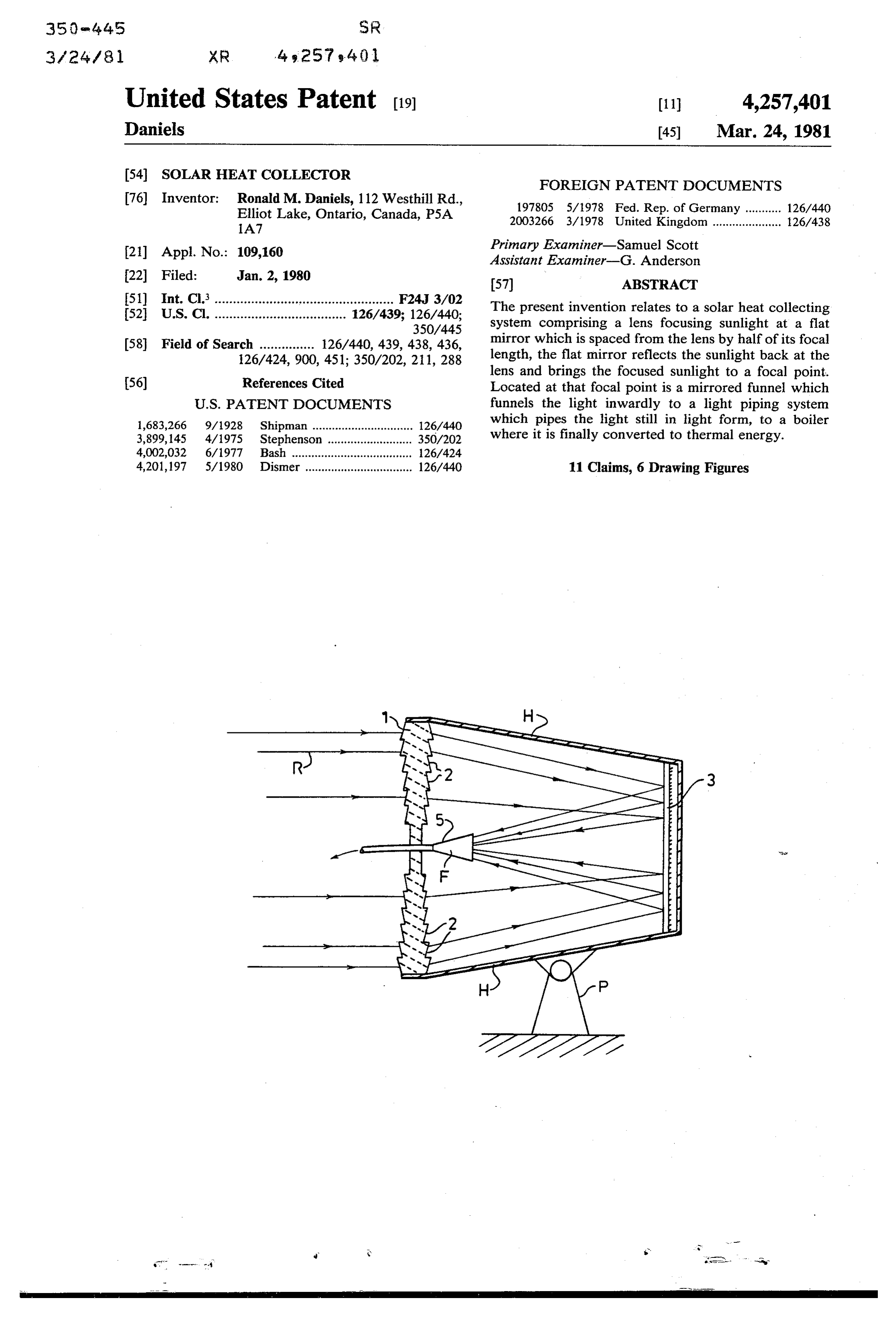
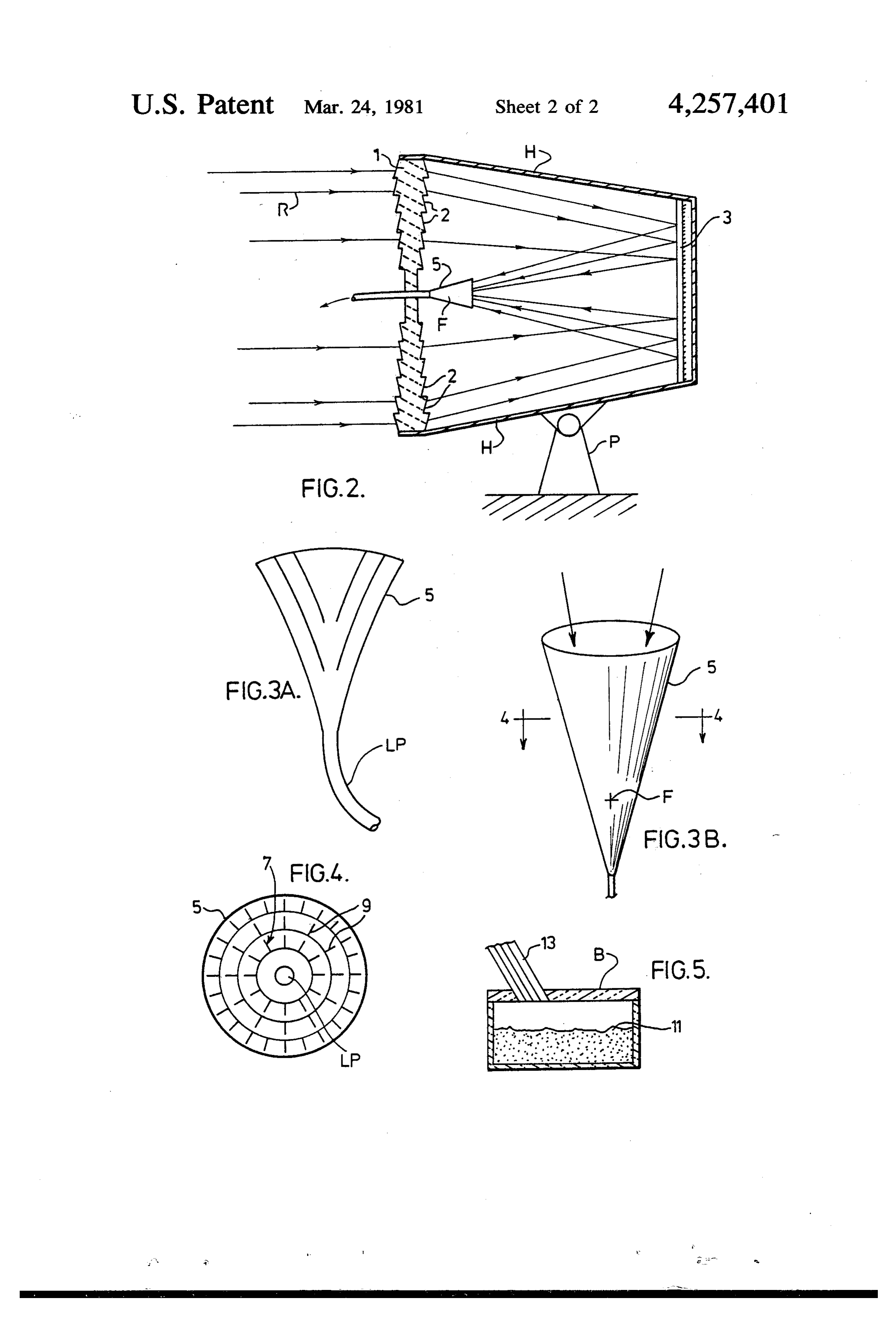
FIG. 2 is a sectional view taken through the area
SOLAR HEAT COLLECTOR indicated at A in FIG. 1.
FIG. 3 is an enlarged view of a preferred funnel ar
FIELD OF THE INVENTION rangement according to the present invention. The present invention relates to a system for collect FIG. 4 is a section taken along the lines 4-4 of FIG.
ing thermal energy from sunlight. FIG. 5 is a section taken through the area indicated at BACKGROUND OF THE INVENTION B in FIG. 1.
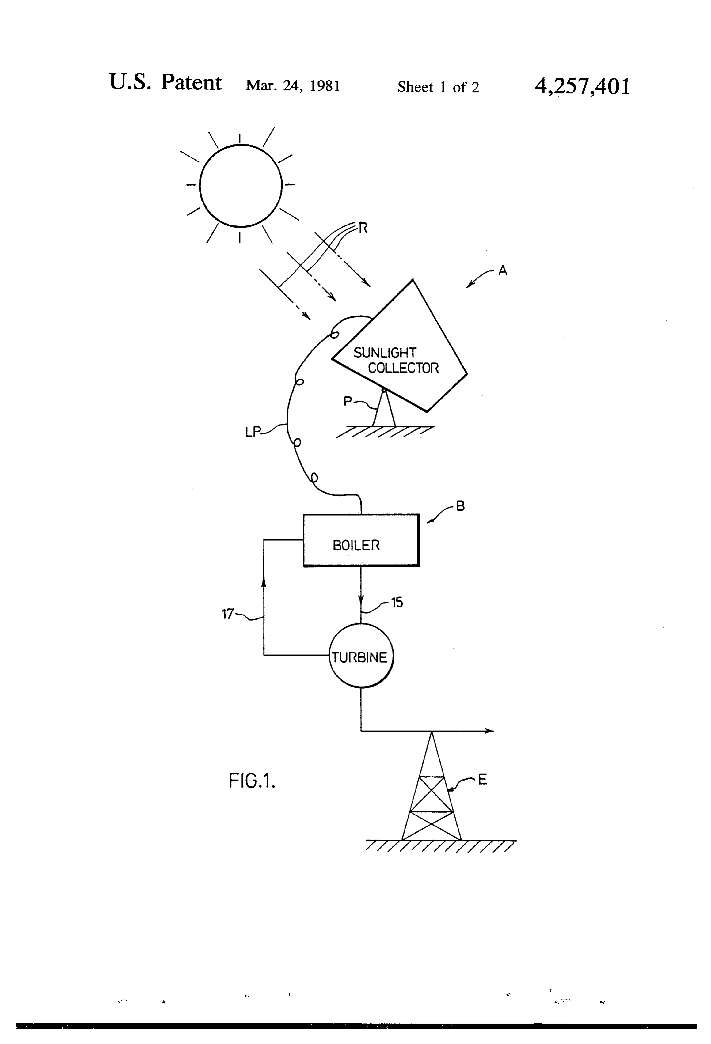
As a result of the recent energy crisis, more and more O tionAnshownoverall preferred scheme for the present inven in FIG. 1 comprises a sunlight collector attempts are being made to collect the heat given off by pivotally mounted as indicated at P to follow the path the sun so that that collected heat can be put to various of the sun for maximum exposure to the sun's rays indi uses where other forms of energy have been used in the cated at R. A light pipe shown at LP is connected to the past. sun collector for transmitting the collected sunlight to For the most parts, the recently developed solar heat 15 the boiler B where the sunlight is converted to thermal collecting arrangements as well as their predecessors energy. This thermal energy is used to produce steam in are extremely complicated and require many different the boiler which drives a turbine shown in FIG. 1. This parts, most of which require frequent maintenance. As a turbine will be preferably used to produce electricity as result, the cost of both setting up and operating the shown at E for domestic use.
prior art arrangements is extremely high. This high cost 20 FIG. 2 shows what I refer to as the sunlight collector is even harder to justify in light of their poor efficiency in greater detail. This collector comprises the forward which is limited by the fact that much of the collected lens 1 which is directly exposed to the sunrays and sunlight is lost as heat energy before it can be put to which focuses the sunlight passing therethrough at a good use. As a general rule, standard heat collecting flat, reflective surface, preferably a flat mirror 3. The systems operate at an unacceptable 35% efficiency due 25 sunlight reflects off the flat mirror and back at the lens to their large surface areas undesirably radiating off where the sunlight comes to a focal point F. A funnel 5 much of the collected heat energy. is located at the focal point. Funnel 5 has an inner re The present invention relates to a solar heat collect flective or mirrored surface 7 which reflects and funnels ing system which is generally much less complicated the light inwardly so that it enters the light pipe while and less expensive than conventional systems. At the 30 remaining in the light energy form.
same time, the solar heat collecting system of the pres The light collector is provided with an external hous ent invention operates above the standard 35% effi ing H extending from the periphery of lens 1 to the ciency point by minimizing the surface areas and heat periphery of mirror 3. As such, the inner reflective surface of the mirror as well as the entirety of funnel 5 losses.
The solar heat collecting system of the present inven 35 are enclosed within the housing making them essentially tion comprises a lense which is pointed at the sun hav operationmaintenance free. This drastically reduces the cost of ing a focal length for focusing sunlight at a flat reflec of the present system. tive surface. The flat reflective surface is spaced from formed fromwhich
Lens 1 is preferably circular in shape, is the lense by half of its focal length and is positioned to 40 2. Each of these segmentsofwhich a plurality integral prismatic segments acts as a prism, deflects reflect the sunlight back at the lens and to bring sunlight to a focal point. Located at this focal point is a symmet the sunlight entering through the lens in a manner con rical funnel means having an inwardly tapered reflec sistent with that of a standard convex lens. However, tive inner surface for funnelling the sunlight to light the prismatic segmented lens of the present invention is much lighter than a conventional convex lens in that it piping means. The light piping means carries the sun 45 requires light still in the light energy form to a boiler where it is reduced less material to perform the same function. The ultimately converted to thermal energy. The thermal for the trackingofofthethelenssunmakes weight it particularly suitable energy collected at this point is then put to efficient use. addition, the shaping of the lens as light by the shown collector. In in FIG. 2
As a result of the construction of the present inven reduces the likelihood of its cracking during formation. tion, both the flat reflective surface and the funnelling 50 In the past, there has been a difficulty when molding means may be totally enclosed against the entrance of convex lenses in glass or in plastic due to the thick dirt, dust, moisture, etc., which essentially eliminates material cracking internally when cooling. This diffi the requirement of constant maintenance to these com culty is essentially eliminated by the prismatic lens de ponents. Therefore, both the cost of setting up and scribed above.
operating the present invention structure is much lower 55 A preferred arrangement for the funnel 5 is shown in than prior art arrangements. In addition, its efficiency FIG. 4. According to this preferred arrangement, the relative to its cost is considerably greater than standard inner reflective surface 7 of the funnel is provided with arrangements due to the fact that the collected sunlight a plurality of small ribs 9 which enhance the funnelling is maintained in a light energy form until it reaches the action of the funnel in angling the sunlight inwardly to boiler which greatly reduces inefficient heat losses. 60 the light pipe.
BRIEF DISCUSSION OF THE DRAWINGS The light pipe itself, may take a number of forms including a curved glass tube or a fiber optics bundle.
The above, as well as other features and advantages Such a bundle consists of a large number of glass fila of the present invention will be described in greater ments, each of which is coated with a reflective material detail according to the preferred embodiments of the 65 to make the filaments totally internally reflecting. Ac present invention wherein: cordingly, as the sunlight enters one end of the bundle, FIG. 1 is an overall schematic of a preferred solar along the axis of the filaments it is maintained in the heat collecting system of the present invention. light energy form throughout the fiber optics bundle,
Page 5
even though the bundle is curved or bent along its 1. A solar heat collecting system comprising a lens length. The same result is accomplished using the glass having a focal length for focusing sunlight at a flat tube which is also internally reflecting so that the light reflective surface which is spaced from said lens by half is carried to the boiler and enters the boiler as light of said focal length, said flat reflective surface being energy. positioned to reflect the sunlight back at the lens and to A plurality of glass fibers 13 are shown entering the bring the sunlight to a focal point; symmetrical funnel boiler in FIG. 5. The light energy enters the boiler havingmeans at said focal point, said symmetrical funnel means through these glass fibers and strikes powdered material funneling an inwardly tapering reflective inner surface for 11 in the form of powder coal or powder graphite to 10 the sunlight to light piping means for piping the light to a boiler where the sunlight is converted to convert the light energy to thermal energy. This con thermal version causes the water in the boiler to turn to steam. energy.
This steam is forced out of the boiler through pipe 15 to 2. A solar heat collecting system as claimed in claim drive the turbine. By way of example, there may be up 1 wherein
said flat reflective surface is a flat mirror.
solar heat collecting system as claimed in claim to 100 sunlight collectors feeding each boiler and there 15 1 wherein said light piping means is a glass tube. may be 10 or more boilers for each steam generator. 4. A solar heat collecting system as claimed in claim Electricity generated by the turbine is usable on a 24 1 wherein said light piping means is a fibre optics bun hour basis in which case 2 lakes of different elevation are used by pumping water up during daylight time and dle.5. A solar heat collecting system as claimed in claim larger hydro-electric turbines are used to operate 24 hours or peak loading. The lake on top could have a 20 a1 plurality wherein said funnel means comprises a funnel having of inner mirrored surfaces for funneling the possible 2 week or so reserve. The rate of lake water light inwardly to a glass tube for carrying the light to evaporation would be considered in the hydro-electric the boiler.
phase of operation. The arrangement may be set up such 6. A solar heat collecting system as defined in claim 5 that solar generated electricity is provided at a constant 25 wherein rate or it may be designed oversized to cover the peaks a pluralitysaid funnel is provided on its inner surface with of small ribs to enhance the inward funneling of industrial and domestic electrical requirements. of the sunlight to the glass tube. The pivot and rotation of the sunlight collector as 7. A solar heat collecting system as defined in claim 2, sembly is computer controlled. The computer may be wherein said flat mirror and said funnel means are en provided with a safety feature to turn the light collector 30 closed within said system to essentially eliminate main away from the sun in the event of overheating. A desert tenance to the flat mirror and the funnel means. location is particularly suitable for the present invention 8. A solar heat collecting system as defined in claim 1 as a result of the intensity of the sunlight in such a loca wherein said lens is essentially circular around its pe tion. riphery and is formed across its diameter by a plurality In view of the description above, it will now be well 35 of integral generally prismatic segments focusing the understood that the present invention which occupies sunlight inwardly to the flat reflective surface. less space than many solar heat collectors and which is 9. A solar heat collecting system as defined in claim 8 relatively uncomplicated, operates on an efficient man wherein said prismatic segments are of increasing size ner by maintaining the collected sunlight in a light en with increasing diameter.
ergy form without exposing it to large heat radiating 10. A solar heat collecting system as claimed in claim surfaces until it can be efficiently converted to thermal 1 wherein said boiler is partially filled with a powder energy. It is also to be appreciated that although various material selected from the group of powder materials embodiments of the invention have been described consisting of powder coal and powder graphite for herein, in detail, one skilled in the art can make varia converting the sunlight to thermal energy. tions to those preferred embodiments without departing 45 11. A solar heat collecting system as defined in claim from the spirit of the invention or the scope of the ap 7 wherein said lens, said flat mirror and said funneling pended claims. means are fixed relative to one another and are mounted The embodiments of the invention in which an exclu on pivot means for following the sun during its travel sive property or privilege is claimed are defined as across the sky for maximum sk k sk exposure
to the sunlight.
follows: 50
Provenance
- Collection
- Cited prior art
- Original PDF
- patentimages.storage.googleapis.com →
- Filed
- 1980-01-02
- Pages
- 5
- Method
- pdftotext (the PDF's own text layer) + pdftoppm 300dpi page scans
- Source
- Google Patents bibliographic record
- Granted
- 1981-03-24
- Inventors
- Ronald M. Daniels
- Transcribed from
- patentimages.storage.googleapis.com →