patent · US4114600
Thermal storage and heat transfer system and method
19 September 1978
Page 1 — bibliographic record
United States Patent (19) 11) 4,114,600 Newton 45) Sep. 19, 1978 (54) THERMAL STORAGE AND HEAT Attorney, Agent, or Firm-C. Hercus Just TRANSFER SYSTEMAND METHOD 57 ABSTRACT 75) Inventor: Alwin B. Newton, York, Pa. A thermal storage and heat transfer system for use with 73) Assignee: Solation Products, Inc., York, Pa. a solar energy heat collector comprising a tank having a plurality of temperature zones therein each zone hav (21) Appl. No.: 730,212 ing, preferably, a plurality of layers of closely arranged 22 Filed: Oct. 6, 1976 cells of irregular shape occupying a minimum space to provide a maximum number of cells in said space in a 51) Int. Cl. .......................... F28D 21/00; F24J 3/02 manner to provide ample passages between the cells for 52 U.S. C. .................................... 126/271; 126/400; a liquid heat transfer medium to contact and move past 165/104 S appreciable surface areas to effect heat transfer to and 58) Field of Search ............... 165/104 S, DIG. 4, 10; from said medium, said cells in said zones respectively 126/400, 271 having sealed therein different heat storage mediums of 56) References Cited a nature to develope a substantially constant latent heat
of fusion temperature when changing from liquid to solid state at a predetermined temperature, and a pump 2,342,211 2/1944 Newton ........................ 165/104 S X connected to said tank and operable to circulate said 2,499,043 2/1950 Voorhees ... ... 165/DIG. 4 heat transfer medium through said passages from and to 3,107,052 10/1963 Garrison ...... ... 126/271 X a solar heat collector. The prefered shape of said cells is 3,200,877 8/1965 Lehmer et al... . 165/104 S X a tetrahedron or a similar simple solid geometric config 3,289,743 12/1966 Biro ........................................ 165/10 uration.
Primary Examiner-Albert W. Davis, Jr. 17 Claims, 10 Drawing Figures
Page 2
Drawing sheet — no readable text.
Page 3
Drawing sheet — no readable text.
Page 4
having sealed therein a heat storage medium comprising
THERMAL STORAGE AND HEAT TRANSFER a chemical capable of changing from liquid to solid state SYSTEMAND METHOD to develop latent heat of fusion at a predetermined, BACKGROUND OF THE INVENTION substantially constant temperature so that, when the heat transfer medium such as water is initially heated to
The utilization of solar energy for space heating and a temperature by the solar heat collector which is above cooling has been the subject of various developments the melting point of the heat storage medium and the for a substantial period of time. Until the recent energy temperature of the transfer medium decreases by use to crisis which occured due to scarcity of oil for heating a temperature less than said melting point, the solidifica purposes and generation of electric current, practical 10 tion of said heat storage medium produces a substantial adaptation of solar energy for heating and cooling, and amount of useful auxiliary heat comprising the latent particularly the actual employment thereof for such heat of fusion of said heat storage medium. purposes, was not seriously undertaken. Now that suit It is another object of the invention to provide several able substitutes for oil and other petroleum products as different types of storage tanks and arrangements in said sources of energy are being considered seriously, the 15 tanks in which the aforementioned phenomenon is uti availability of solar energy for such purposes is very lized in a highly efficient manner. apparent. After the initial installation of a system to Ancillary to the foregoing object, it is a further object employ this form of energy, operation of the same is to provide in said storage tanks several different ar relatively inexpensive, even when supplemental electri rangements of Zones in which the heat storage medium cal energy is required to augment solar energy to pro 20 employed respectively in said zones in different in order vide a full schedule of operation of the system. that different temperature ranges may be developed in Various types of solar heat collector systems have said Zone for the purposes described hereinafter, all been developed heretofore and some of these have now leading to efficient operation of the system. been placed in operation. While not directly related to One further object of the invention is to encapsulate the present invention, except as an example of one type 25 the desired heat storage medium in closely associated, of solar energy collector system, the present applicant and preferably physically connected, cells in which the has a co-pending application, Ser. No. 657,883, filed heat storage medium is sealed and, related to this object, Mar. 4, 1976 and entitled Solar Heat Collector, this it is a still further object to employ cells which are in the collector being suitable for use with the thermal storage shape of tetrahedrons which, for example, may be and heat transfer system and method comprising the 30 formed from flexible tubular plastic material capable of present invention. In some thermal storage and heat having opposite walls thereof squeezed together by transfer systems which have been developed hereto heated means capable of causing sealing adherance of fore, heat exchange apparatus has been used in which said opposite walls so as effectively to enclose a selected the heat storage medium which is heated by the solar heat storage medium within said cells by relatively heat collector, and is circulated through the thermal 35 simple apparatus, the resulting product comprising a storage system, comprises water. Similarly, the heat series of tetrahedrons when successive sealing compres transfer medium also comprises water. Depending upon sions of the tube at selected interval are at right angles the type and amount of insulation associated with the to each other, a further attribute of such formation system and especially the storage tank, water is rela being that alternate sealing areas in the continuous ar tively useful as a heat storage medium but it is possible 40 rangement thereof are capable of functioning as hinge to improve the usefulness of a thermal energy storage sections, whereby a predetermined continuous length of system by utilizing a heat storage medium in the form of such tetrahedrons may be arranged in a coiled configu a chemical substance or compound capable of changing ration substantially within a common plane and provide from liquid to solid state at a predetermined tempera ample passages between adjacent convolutions of said ture and thereby developing latent heat of fusion at said 45 tetrehedrons for the passage of liquid heat transfer me temperature which is substantially constant. The princi dium, such as water, through said passages. ple of deriving such latent heat of fusion from various Still another object of the invention is to arrange said chemical compound and substantices is well known but, aforementioned coiled arrangements of tetrahedrons in thus far, relatively little use of the same in association layers which are either immediately on top of each with thermal storage system has been undertaken. The 50 other, separated by perforated diaphragms, or separated present invention, however, utilizes this principle to by substantially imperforate diaphragms successively distinct advantage in association with apparatus struc having openings therein in different locations to effect a ture and the method performed by such structure, de circuitous path for the liquid heat transfer medium, such tails of which are set forth hereinafter. as water, between successive layers of said coiled cells 55 containing the heat storage medium.
SUMMARY OF THE INVENTION Ancillary to the foregoing object, is a further object It is the principal object of the present invention to of the invention in utilizing relatively imperforate dia provide a thermal storage and heat transfer system phragms to provide successive diaphragms respectively which employs solar energy as the source of heat for with a passage opening in the center and one or more purposes of heating a liquid heat transfer medium, such 60 passage openings adjacent the periphery thereof, as water, into and through a tank in which a plurality of whereby when each of the diaphragms is thus arranged, heat storage cells of irregular shape are positioned in an effective circuitous path for the liquid heat transfer mediately adjacent each other in very compact relation medium is provided between said layers of coiled cells. ship and in which, due to the irregular shape of said A still further object of the invention is to provide in cells, highly adequate and substantial passages are pro 65 one embodiment a tank in which two or more zones are vided in said tank between said cells for the circulation provided by means of relatively imperforate horizontal of said liquid heat transfer medium therethrough in plates extending transversely between opposite sides of contact with the exterior surfaces of said cells, the cells said tank, circulation of liquid transfer medium between
Page 5
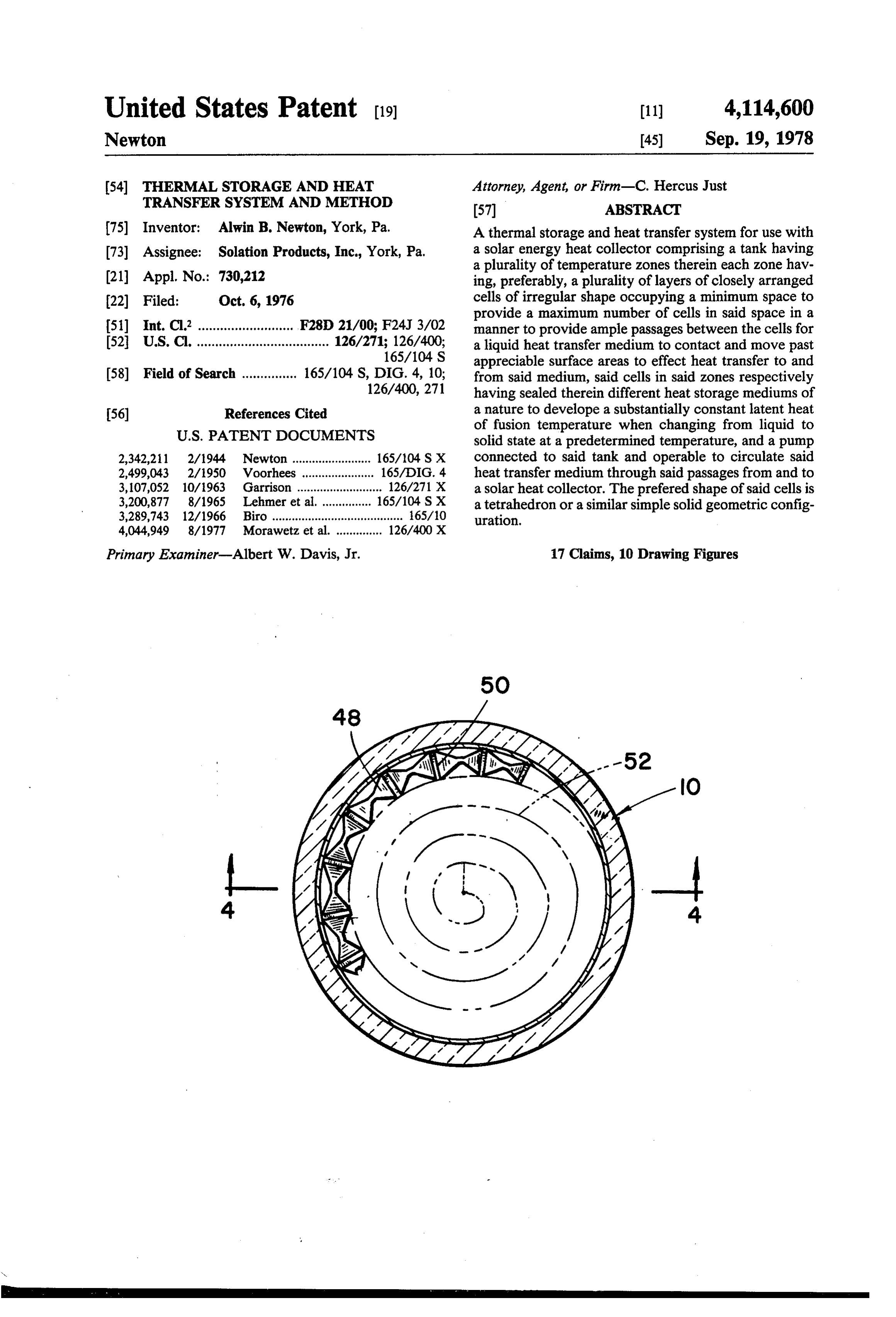
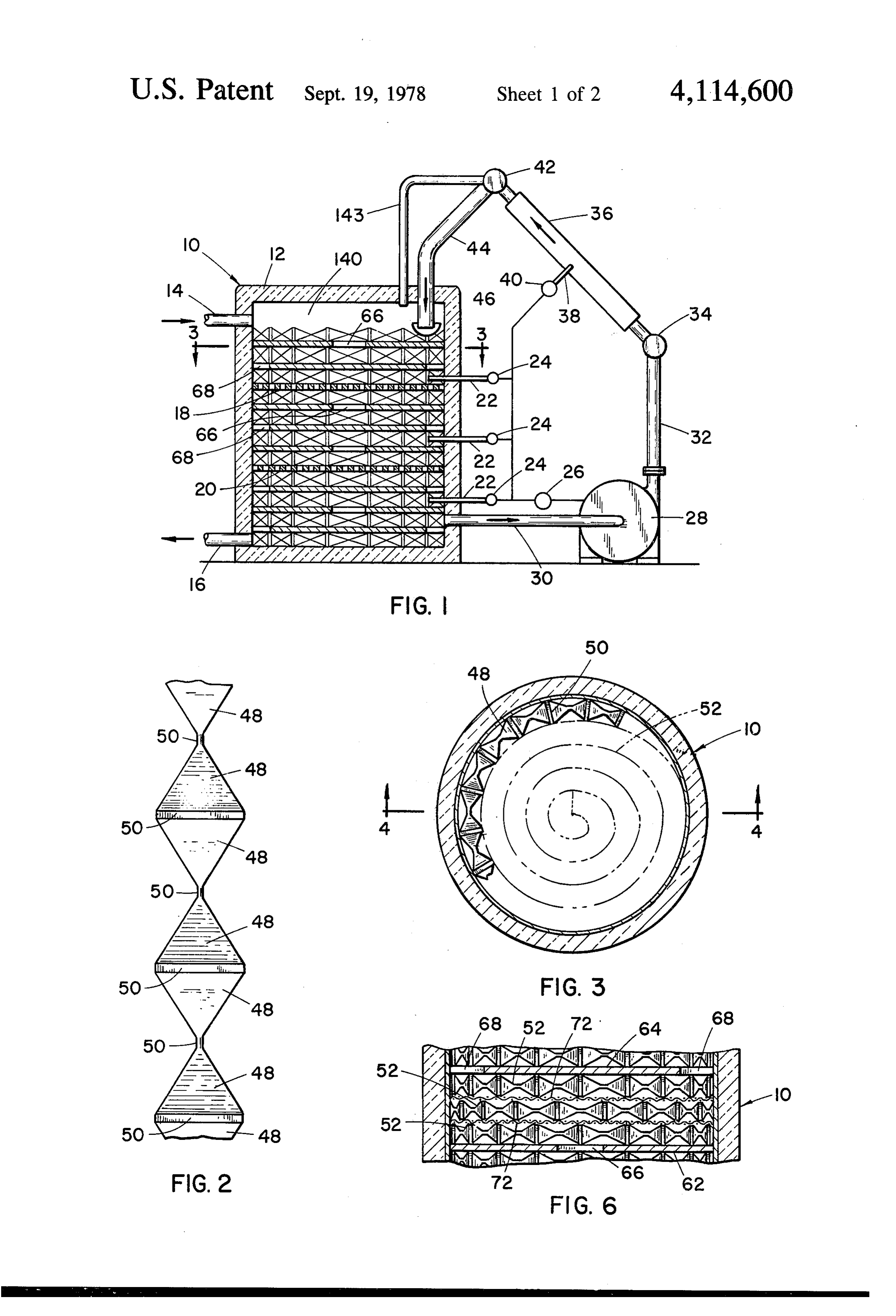
said zones and the solar heat collector may be effected theFIG. 4 is a fragmentary vertical section of the part of system shown in FIG. 3 as seen on the line 4-4 by sets of elongated tubes comprising inner and outer thereof.
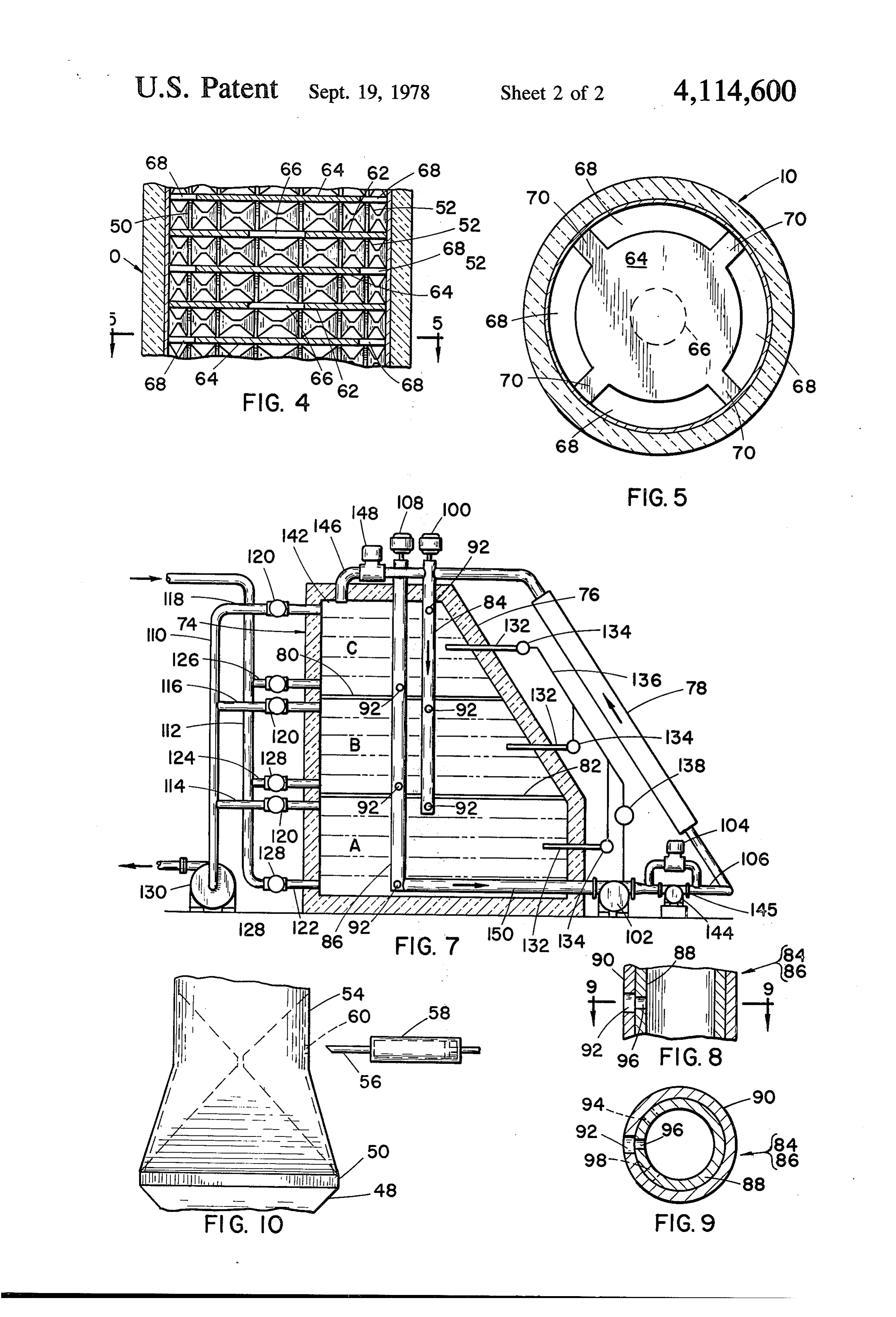
tubes, one of said tubes having one opening located FIG. 5 is a horizontal sectional view of the part of the therein for each zone and the other tube having a plural 5 system shown in FIG. 4 as seen on the line 5-5 thereof. ity of circularly spaced openings therein at a plurality of FIG. 6 is a fragmentary vertical sectional view of a levels corresponding to the spacings of the openings in further embodiment of the invention and illustrating a the first mentioned tube, whereby when the tubes are portion thereof similar to that illustrated in FIG. 4. relatively rotated about their axes, said opening in the FIG. 7 is a vertical elevation, partly in section, illus respective tubes form valve means to control the distri trating another embodiment of the system comprising bution and circulation of the liquid heat transfer me 10 the present invention.
dium between said zones and said solar heat collector. FIG. 8 is a fragmentary vertical section of a detail of It is still another object of the invention to arrange some of the valve means employed in the embodiment sensor devises in each zone of said tanks, said sensors shown in FIG. 7.
operating thermal switches connected in circuit with an FIG. 9 is a transverse sectional view of the detail electric motor which operates a circulating pump for shown in FIG. 8 as seen on the line 9-9 thereof. the liquid heat transfer medium and thereby automati FIG. 10 is a fragmentary vertical elevation illustrat cally provides for circulation of said medium within any ing one embodiment of exemplary means to fill the cells zone of said tanks in which the sensor has activated the with heat storage medium to produce the arrangement pump for purposes of circulating said heat transfer me 20 shown in FIG. 2.
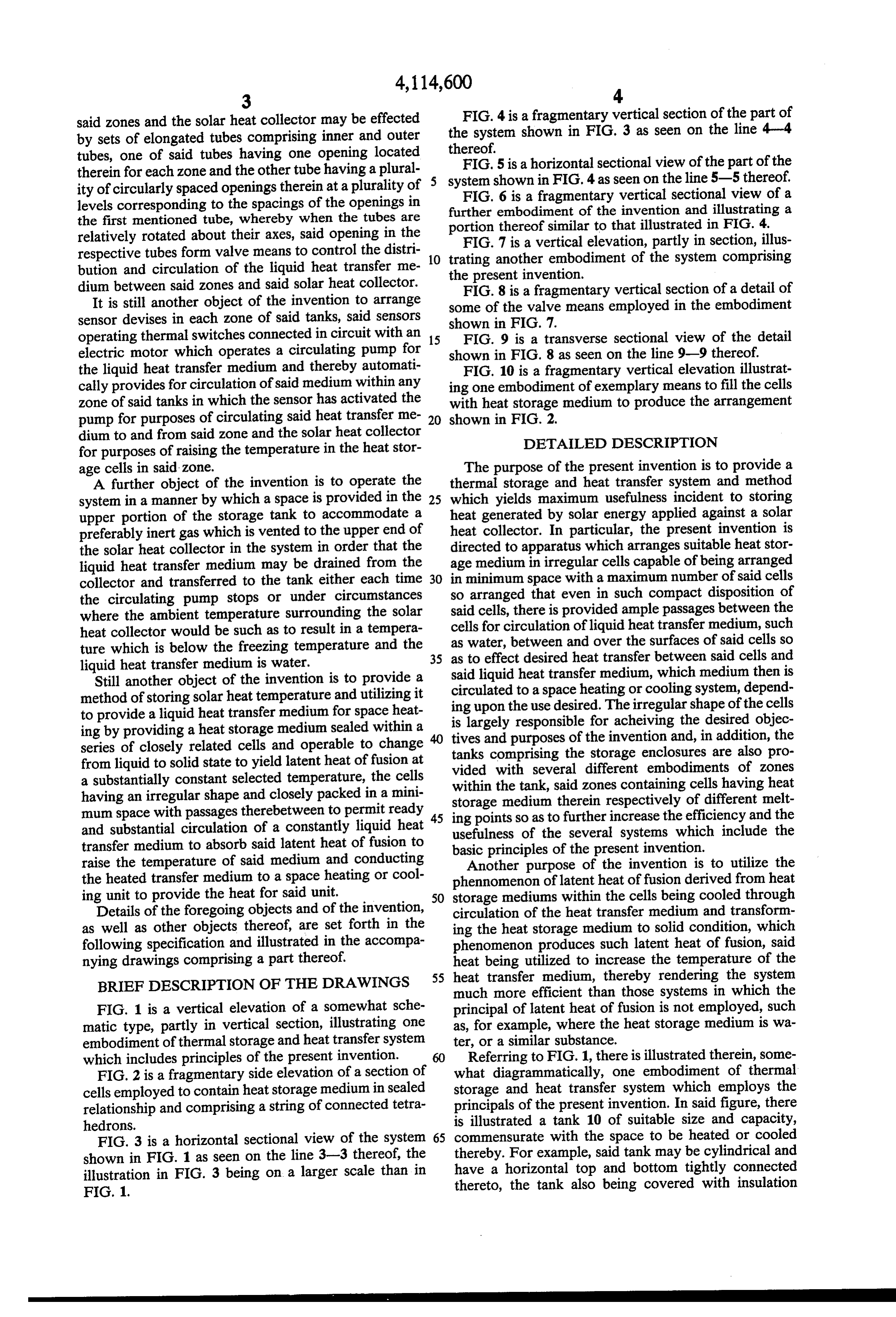
dium to and from said zone and the solar heat collector for purposes of raising the temperature in the heat stor DETAILED DESCRIPTION age cells in said zone. The purpose of the present invention is to provide a A further object of the invention is to operate the thermal storage and heat transfer system and method system in a manner by which a space is provided in the 25 which yields maximum usefulness incident to storing upper portion of the storage tank to accommodate a heat generated by solar energy applied against a solar preferably inert gas which is vented to the upper end of heat collector. In particular, the present invention is the solar heat collector in the system in order that the directed to apparatus which arranges suitable heat stor liquid heat transfer medium may be drained from the age medium in irregular cells capable of being arranged collector and transferred to the tank either each time 30 in minimum space with a maximum number of said cells the circulating pump stops or under circumstances so arranged that even in such compact disposition of where the ambient temperature surrounding the solar said cells, there is provided ample passages between the heat collector would be such as to result in a tempera cells for circulation of liquid heat transfer medium, such ture which is below the freezing temperature and the as as water, between and over the surfaces of said cells so to effect desired heat transfer between said cells and liquid heat transfer medium is water. 35 said
Still another object of the invention is to provide a circulated liquid heat transfer medium, which medium then is method of storing solar heat temperature and utilizing it ing upon theto use a space heating or cooling system, depend desired. The irregular shape of the cells to provide a liquid heat transfer medium for space heat is largely responsible for acheiving the desired objec ing by providing a heat storage medium sealed within a tives and purposes of the invention and, in addition, the series of closely related cells and operable to change tanks comprising the storage from liquid to solid state to yield latent heat of fusion at vided with several different enclosures are also pro embodiments of zones a substantially constant selected temperature, the cells within the tank, said zones containing cells having heat having an irregular shape and closely packed in a mini storage mum space with passages therebetween to permit ready 45 ing pointsmedium therein respectively of different melt so as to further increase the efficiency and the and substantial circulation of a constantly liquid heat usefulness of the several systems which include the transfer medium to absorb said latent heat of fusion to basic principles of the present invention. raise the temperature of said medium and conducting Another purpose of the invention is to utilize the the heated transfer medium to a space heating or cool phennomenon of latent heat of fusion derived from heat ing unit to provide the heat for said unit. 50 storage mediums within the cells being cooled through Details of the foregoing objects and of the invention, circulation of the heat transfer medium and transform as well as other objects thereof, are set forth in the ing the heat storage medium to solid condition, which following specification and illustrated in the accompa phenomenon produces such latent heat of fusion, said nying drawings comprising a part thereof. heat being utilized to increase the temperature of the BRIEF DESCRIPTION OF THE DRAWINGS 55 heat transfer medium, thereby rendering the system much more efficient than those systems in which the
FIG. 1 is a vertical elevation of a somewhat sche principal of latent heat of fusion is not employed, such matic type, partly in vertical section, illustrating one as, for example, where the heat storage medium is wa embodiment of thermal storage and heat transfer system ter, or a similar substance.
which includes principles of the present invention. 60 Referring to FIG. 1, there is illustrated therein, some FIG. 2 is a fragmentary side elevation of a section of what diagrammatically, one embodiment of thermal cells employed to contain heat storage medium in sealed storage and heat transfer system which employs the relationship and comprising a string of connected tetra principals of the present invention. In said figure, there hedrons. is illustrated a tank 10 of suitable size and capacity, FIG. 3 is a horizontal sectional view of the system 65 commensurate with the space to be heated or cooled shown in FIG. 1 as seen on the line 3-3 thereof, the thereby. For example, said tank may be cylindrical and illustration in FIG. 3 being on a larger scale than in have a horizontal top and bottom tightly connected FIG. 1. thereto, the tank also being covered with insulation
Page 6
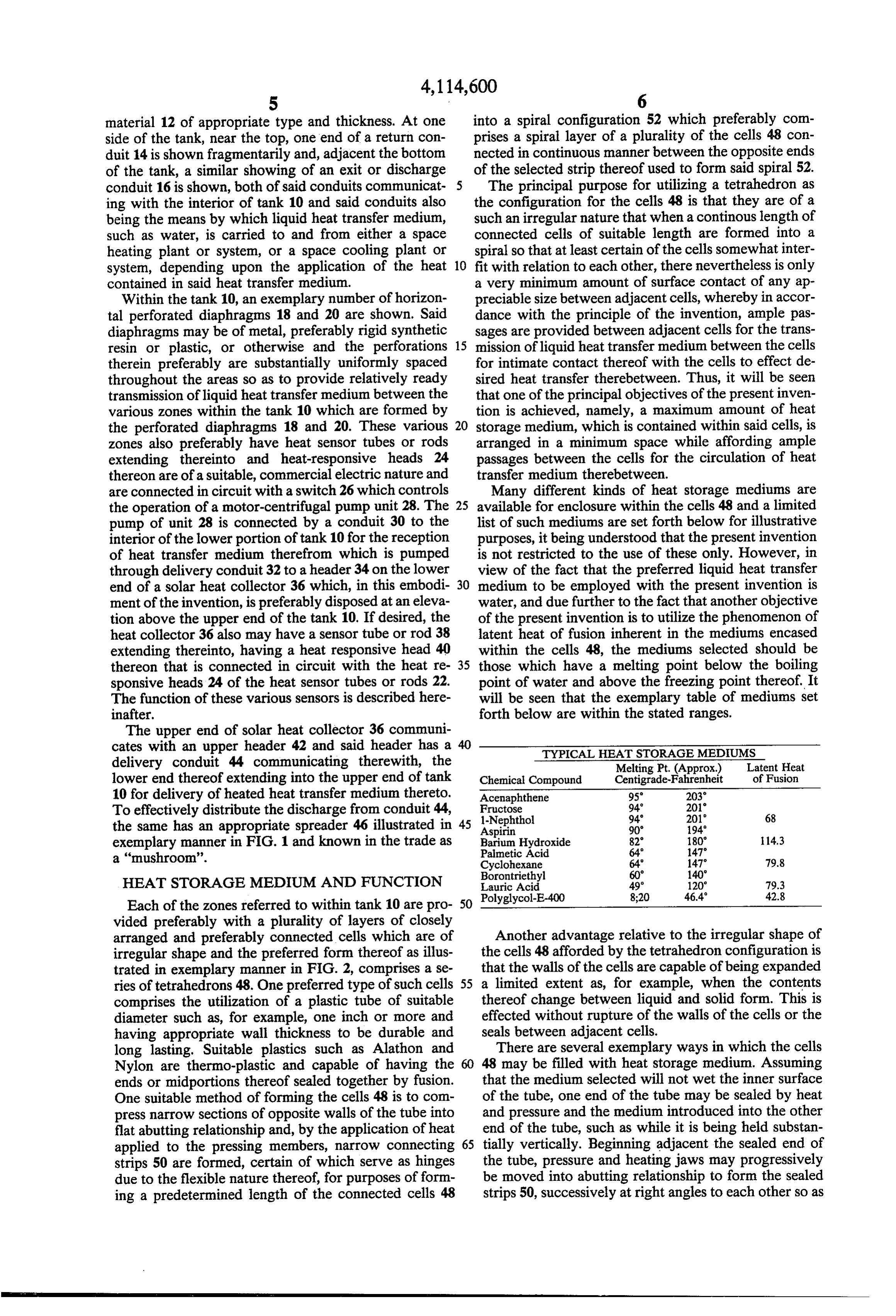
material 12 of appropriate type and thickness. At one into a spiral configuration 52 which preferably com side of the tank, near the top, one end of a return con prises a spiral layer of a plurality of the cells 48 con duit 14 is shown fragmentarily and, adjacent the bottom nected in continuous manner between the opposite ends of the tank, a similar showing of an exit or discharge of the selected strip thereof used to form said spiral 52. conduit 16 is shown, both of said conduits communicat The principal purpose for utilizing a tetrahedron as ing with the interior of tank 10 and said conduits also the configuration for the cells 48 is that they are of a being the means by which liquid heat transfer medium, such an irregular nature that when a continous length of such as water, is carried to and from either a space connected cells of suitable length are formed into a heating plant or system, or a space cooling plant or spiral so that at least certain of the cells somewhat inter system, depending upon the application of the heat 10 fit with relation to each other, there nevertheless is only contained in said heat transfer medium. a very minimum amount of surface contact of any ap Within the tank 10, an exemplary number of horizon preciable size between adjacent cells, whereby in accor tal perforated diaphragms 18 and 20 are shown. Said dance with the principle of the invention, ample pas diaphragms may be of metal, preferably rigid synthetic sages are provided between adjacent cells for the trans resin or plastic, or otherwise and the perforations 15 mission of liquid heat transfer medium between the cells therein preferably are substantially uniformly spaced for intimate contact thereof with the cells to effect de throughout the areas so as to provide relatively ready sired heat transfer therebetween. Thus, it will be seen transmission of liquid heat transfer medium between the that one of the principal objectives of the present inven various zones within the tank 10 which are formed by tion is achieved, namely, a maximum amount of heat the perforated diaphragms 18 and 20. These various 20 storage medium, which is contained within said cells, is zones also preferably have heat sensor tubes or rods arranged in a minimum space while affording ample extending thereinto and heat-responsive heads 24 passages between the cells for the circulation of heat thereon are of a suitable, commercial electric nature and transfer medium therebetween.
are connected in circuit with a switch 26 which controls Many different kinds of heat storage mediums are the operation of a motor-centrifugal pump unit 28. The 25 available for enclosure within the cells 48 and a limited pump of unit 28 is connected by a conduit 30 to the list of such mediums are set forth below for illustrative interior of the lower portion of tank 10 for the reception purposes, it being understood that the present invention of heat transfer medium therefrom which is pumped is not restricted to the use of these only. However, in through delivery conduit 32 to a header 34 on the lower view of the fact that the preferred liquid heat transfer end of a solar heat collector 36 which, in this embodi 30 medium to be employed with the present invention is ment of the invention, is preferably disposed at an eleva water, and due further to the fact that another objective tion above the upper end of the tank 10. If desired, the of the present invention is to utilize the phenomenon of heat collector 36 also may have a sensor tube or rod 38 latent heat of fusion inherent in the mediums encased extending thereinto, having a heat responsive head 40 within the cells 48, the mediums selected should be thereon that is connected in circuit with the heat re 35 those which have a melting point below the boiling sponsive heads 24 of the heat sensor tubes or rods 22. point of water and above the freezing point thereof. It The function of these various sensors is described here will be seen that the exemplary table of mediums set inafter. forth below are within the stated ranges. The upper end of solar heat collector 36 communi cates with an upper header 42 and said header has a 40 TYPICAL HEAT STORAGE MEDUMS delivery conduit 44 communicating therewith, the Melting Pt. (Approx.) Latent Heat lower end thereof extending into the upper end of tank Chemical Compound Centigrade-Fahrenheit of Fusion 10 for delivery of heated heat transfer medium thereto. Acenaphthene 95° 203 To effectively distribute the discharge from conduit 44, Fructose
the same has an appropriate spreader 46 illustrated in 45 Aspirin 90° 194 exemplary manner in FIG. 1 and known in the trade as Barium Hydroxide
Palmetic Acid
a "mushroom'. Cyclohexane 64' 147 79.8
HEAT STORAGE MEDUMAND FUNCTION Lauric Acid 49 120° 79.3
Each of the zones referred to within tank 10 are pro 50 vided preferably with a plurality of layers of closely arranged and preferably connected cells which are of Another advantage relative to the irregular shape of irregular shape and the preferred form thereof as illus the cells 48 afforded by the tetrahedron configuration is trated in exemplary manner in FIG. 2, comprises a se that the walls of the cells are capable of being expanded ries of tetrahedrons 48. One preferred type of such cells 55 a limited extent as, for example, when the contents comprises the utilization of a plastic tube of suitable thereof change between liquid and solid form. This is diameter such as, for example, one inch or more and effected without rupture of the walls of the cells or the having appropriate wall thickness to be durable and seals between adjacent cells.
long lasting. Suitable plastics such as Alathon and There are several exemplary ways in which the cells Nylon are thermo-plastic and capable of having the 48 may be filled with heat storage medium. Assuming ends or midportions thereof sealed together by fusion. that the medium selected will not wet the inner surface One suitable method of forming the cells 48 is to com of the tube, one end of the tube may be sealed by heat press narrow sections of opposite walls of the tube into and pressure and the medium introduced into the other flat abutting relationship and, by the application of heat end of the tube, such as while it is being held substan applied to the pressing members, narrow connecting 65 tially vertically. Beginning adjacent the sealed end of strips 50 are formed, certain of which serve as hinges the tube, pressure and heating jaws may progressively due to the flexible nature thereof, for purposes of form be moved into abutting relationship to form the sealed ing a predetermined length of the connected cells 48 strips 50, successively at right angles to each other so as
Page 7
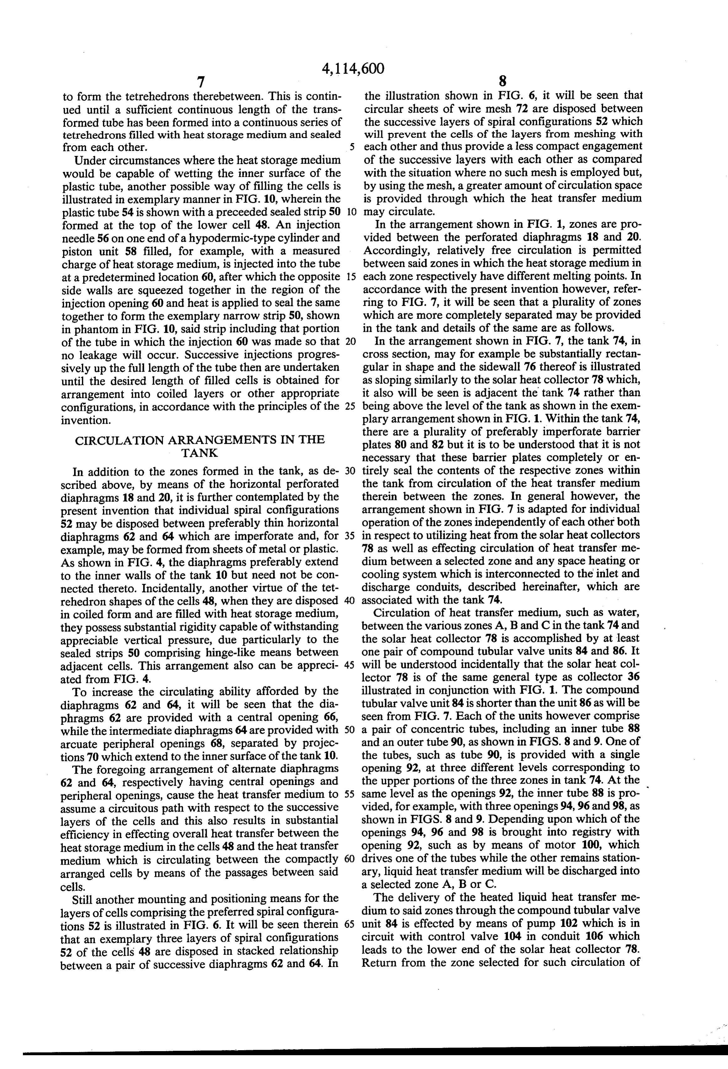
to form the tetrehedrons therebetween. This is contin the illustration shown in FIG. 6, it will be seen that ued until a sufficient continuous length of the trans circular sheets of wire mesh 72 are disposed between formed tube has been formed into a continuous series of the successive layers of spiral configurations 52 which tetrehedrons filled with heat storage medium and sealed will prevent the cells of the layers from meshing with from each other. each other and thus provide a less compact engagement Under circumstances where the heat storage medium of the successive layers with each other as compared would be capable of wetting the inner surface of the with the situation where no such mesh is employed but, plastic tube, another possible way of filling the cells is by using the mesh, a greater amount of circulation space illustrated in exemplary manner in FIG. 10, wherein the is provided through which the heat transfer medium plastic tube 54 is shown with a preceeded sealed strip 50 10 may circulate.
formed at the top of the lower cell 48. An injection In the arrangement shown in FIG. 1, zones are pro needle 56 on one end of a hypodermic-type cylinder and vided between the perforated diaphragms 18 and 20. piston unit 58 filled, for example, with a measured Accordingly, relatively free circulation is permitted charge of heat storage medium, is injected into the tube between said zones in which the heat storage medium in at a predetermined location 60, after which the opposite 15 each zone respectively have different melting points. In side walls are squeezed together in the region of the accordance with the present invention however, refer injection opening 60 and heat is applied to seal the same ring to FIG. 7, it will be seen that a plurality of zones together to form the exemplary narrow strip 50, shown which are more completely separated may be provided in phantom in FIG. 10, said strip including that portion in the tank and details of the same are as follows. of the tube in which the injection 60 was made so that 20 In the arrangement shown in FIG. 7, the tank 74, in no leakage will occur. Successive injections progres cross section, may for example be substantially rectan sively up the full length of the tube then are undertaken gular in shape and the sidewall 76 thereof is illustrated until the desired length of filled cells is obtained for as sloping similarly to the solar heat collector 78 which, arrangement into coiled layers or other appropriate it also will be seen is adjacent the tank 74 rather than configurations, in accordance with the principles of the 25 being above the level of the tank as shown in the exem invention. plary arrangement shown in FIG. 1. Within the tank 74,
CIRCULATION ARRANGEMENTS IN THE
there are a plurality of preferably imperforate barrier
TANK
plates 80 and 82 but it is to be understood that it is not necessary that these barrier plates completely or en
In addition to the zones formed in the tank, as de 30 tirely seal the contents of the respective zones within scribed above, by means of the horizontal perforated the tank from circulation of the heat transfer medium diaphragms 18 and 20, it is further contemplated by the therein between the zones. In general however, the present invention that individual spiral configurations arrangement shown in FIG. 7 is adapted for individual 52 may be disposed between preferably thin horizontal operation of the zones independently of each other both diaphragms 62 and 64 which are imperforate and, for 35 in respect to utilizing heat from the solar heat collectors example, may be formed from sheets of metal or plastic. 78 as well as effecting circulation of heat transfer me As shown in FIG. 4, the diaphragms preferably extend dium between a selected zone and any space heating or to the inner walls of the tank 10 but need not be con cooling system which is interconnected to the inlet and nected thereto. Incidentally, another virtue of the tet discharge conduits, described hereinafter, which are rehedron shapes of the cells 48, when they are disposed associated with the tank 74.
in coiled form and are filled with heat storage medium, Circulation of heat transfer medium, such as water, they possess substantial rigidity capable of withstanding between the various zones A, B and C in the tank 74 and appreciable vertical pressure, due particularly to the the solar heat collector 78 is accomplished by at least sealed strips 50 comprising hinge-like means between one pair of compound tubular valve units 84 and 86. It adjacent cells. This arrangement also can be appreci 45 will be understood incidentally that the solar heat col ated from FIG. 4. lector 78 is of the same general type as collector 36 To increase the circulating ability afforded by the illustrated in conjunction with FIG. 1. The compound diaphragms 62 and 64, it will be seen that the dia tubular valve unit 84 is shorter than the unit 86 as will be phragms 62 are provided with a central opening 66, seen from FIG. 7. Each of the units however comprise while the intermediate diaphragms 64 are provided with 50 a pair of concentric tubes, including an inner tube 88 arcuate peripheral openings 68, separated by projec and an outer tube 90, as shown in FIGS. 8 and 9. One of tions 70 which extend to the inner surface of the tank 10.the tubes, such as tube 90, is provided with a single The foregoing arrangement of alternate diaphragms opening 92, at three different levels corresponding to 62 and 64, respectively having central openings and the upper portions of the three zones in tank 74. At the peripheral openings, cause the heat transfer medium to 55 same level as the openings 92, the inner tube 88 is pro assume a circuitous path with respect to the successive vided, for example, with three openings 94,96 and 98, as layers of the cells and this also results in substantial shown in FIGS. 8 and 9. Depending upon which of the efficiency in effecting overall heat transfer between the openings 94, 96 and 98 is brought into registry with heat storage medium in the cells 48 and the heat transfer opening 92, such as by means of motor 100, which medium which is circulating between the compactly drives one of the tubes while the other remains station arranged cells by means of the passages between said ary, liquid heat transfer medium will be discharged into cells. a selected zone A, B or C.
Still another mounting and positioning means for the The delivery of the heated liquid heat transfer me layers of cells comprising the preferred spiral configura dium to said zones through the compound tubular valve tions 52 is illustrated in FIG. 6. It will be seen therein 65 unit 84 is effected by means of pump 102 which is in that an exemplary three layers of spiral configurations circuit with control valve 104 in conduit 106 which 52 of the cells 48 are disposed in stacked relationship leads to the lower end of the solar heat collector 78. between a pair of successive diaphragms 62 and 64. In Return from the Zone selected for such circulation of
Page 8
heat transfer medium is effected by compound tubular accomplished by utilizing the various embodiments of valve unit 86 which, as seen from FIG. 7, has a single the present invention.
opening 92 at three different levels in the outer tube 90 In both embodiments of the invention respectively thereof, preferably adjacent the lower portion of each shown in FIGS. 1 and 7, the level of the heat transfer of said zones, and motor 108 drives one of the tubes 88 medium in the uppermost zone in the tank is spaced or 90 of the compound unit 86 to connect one of the from the top of the tank in order to provide a space 140 openings 94,96 or 98 of the inner tube 90 of unit 86 with in tank 10 of FIG. 1 and a space 142 in tank 74 of FIG. the single opening 92 at the level selected for circulation7 for purposes of accommodating a gas which prefera in the desired zone. It will be understood that the mo bly is of an inert type, such as nitrogen. This gas primar tors 100 and 108 operate in unison in a manner to open 10 ily is for purposes of venting the solar heat collector to the openings 92 in each of the tubular valve units 84 and remove the heat transfer medium therefrom under cer 86 for circulation through a single zone only. tain conditions. For example, in the embodiment shown For purposes of distributing the liquid heat transfer in FIG. 1, the solar heat collector 36 preferably is medium which is circulated through the various Zones drained of heat transfer medium such as water each time of the tank 74 to either a space heating or cooling sys 15 the pump 28 stops following the equalizing of the tem tem connected to the unit shown in FIG. 7, the tank 74 perature of the heat transfer medium in the tank 10 in has additional conduits connected thereto for that pur accordance with the demand of the type of system, pose. In FIG. 7, a pair of substantially vertical conduits heating or cooling, with which the tank is associated. 110 and 112 are of sufficient length in a vertical direc When this occurs, the inert gas in the space 140 of tank tion to afford connection of branch conduits 114, 116 20 10 in FIG. 1 is transmitted by vent tube 143 to the solar and 118 respectively to zones A, B and C which respec heat collector by virtue of vacuum occuring therein tively have control valves 120 therein to control com after the liquid has been withdrawn from the collector munication with said zones of tank 74. Similarly, con by operation of pump 28.
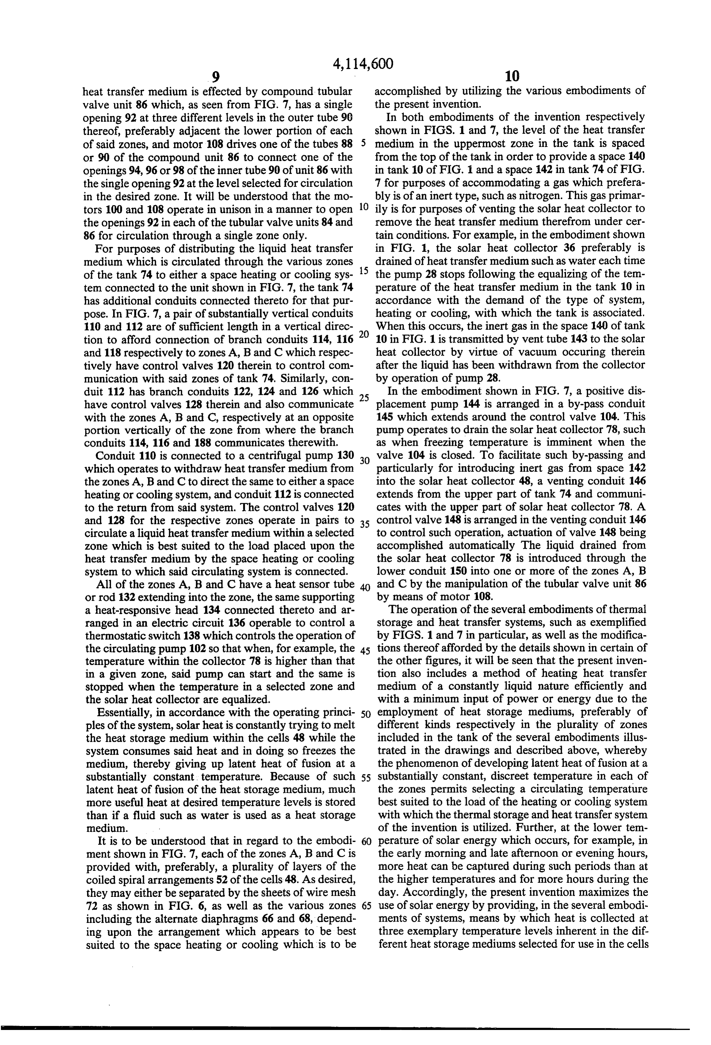
duit 112 has branch conduits 122, 124 and 126 which 25 In the embodiment shown in FIG. 7, a positive dis have control valves 128 therein and also communicate placement pump 144 is arranged in a by-pass conduit with the zones A, B and C, respectively at an opposite 145 which extends around the control valve 104. This portion vertically of the zone from where the branch pump operates to drain the solar heat collector 78, such conduits 114, 116 and 188 communicates therewith. as when freezing temperature is imminent when the Conduit 110 is connected to a centrifugal pump 130 30 valve 104 is closed. To facilitate such by-passing and which operates to withdraw heat transfer medium from particularly for introducing inert gas from space 142 the zones A, B and C to direct the same to either a space into the solar heat collector 48, a venting conduit 146 heating or cooling system, and conduit 112 is connected extends from the upper part of tank 74 and communi to the return from said system. The control valves 120 cates with the upper part of solar heat collector 78. A and 128 for the respective zones operate in pairs to 35 control valve 148 is arranged in the venting conduit 146 circulate a liquid heat transfer medium within a selected to control such operation, actuation of valve 148 being zone which is best suited to the load placed upon the accomplished automatically The liquid drained from heat transfer medium by the space heating or cooling the solar heat collector 78 is introduced through the system to which said circulating system is connected. lower conduit 150 into one or more of the zones A, B All of the zones A, B and C have a heat sensor tube and C by the manipulation of the tubular valve unit 86 or rod 132 extending into the zone, the same supporting by means of motor 108.
a heat-responsive head 134 connected thereto and ar The operation of the several embodiments of thermal ranged in an electric circuit 136 operable to control a storage and heat transfer systems, such as exemplified thermostatic switch 138 which controls the operation of by FIGS. 1 and 7 in particular, as well as the modifica the circulating pump 102 so that when, for example, the 45 tions thereof afforded by the details shown in certain of temperature within the collector 78 is higher than that the other figures, it will be seen that the present inven in a given zone, said pump can start and the same is tion also includes a method of heating heat transfer stopped when the temperature in a selected zone and medium of a constantly liquid nature efficiently and the solar heat collector are equalized. with a minimum input of power or energy due to the Essentially, in accordance with the operating princi 50 employment of heat storage mediums, preferably of ples of the system, solar heat is constantly trying to melt different kinds respectively in the plurality of zones the heat storage medium within the cells 48 while the included in the tank of the several embodiments illus system consumes said heat and in doing so freezes the trated in the drawings and described above, whereby medium, thereby giving up latent heat of fusion at a the phenomenon of developing latent heat of fusion at a substantially constant temperature. Because of such 55 substantially constant, discreet temperature in each of latent heat of fusion of the heat storage medium, much the zones permits selecting a circulating temperature more useful heat at desired temperature levels is stored best suited to the load of the heating or cooling system than if a fluid such as water is used as a heat storage with which the thermal storage and heat transfer system medium. of the invention is utilized. Further, at the lower tem It is to be understood that in regard to the embodi perature of solar energy which occurs, for example, in ment shown in FIG. 7, each of the zones A, B and C is the early morning and late afternoon or evening hours, provided with, preferably, a plurality of layers of the more heat can be captured during such periods than at coiled spiral arrangements 52 of the cells 48. As desired, the higher temperatures and for more hours during the they may either be separated by the sheets of wire mesh day. Accordingly, the present invention maximizes the 72 as shown in FIG. 6, as well as the various zones 65 use of solar energy by providing, in the several embodi including the alternate diaphragms 66 and 68, depend ments of systems, means by which heat is collected at ing upon the arrangement which appears to be best three exemplary temperature levels inherent in the dif suited to the space heating or cooling which is to be ferent heat storage mediums selected for use in the cells
Page 9
respectively positioned operatively within the different 4. The system according to claim 3 in which the zones within the tanks. openings in alternate diaphragms are disposed adjacent From the foregoing, it will be seen that due to the the rims thereof and the diaphragms therebetween have present invention employing cells of an irregular shape substantially central openings therein to effect said cir to contain a selected heat storage medium in order that cuitious paths for said liquid heat transfer medium. said irregular shapes of the cells may be arranged in 5. The system according to claim 1 in which said cells compact manner to accommodate a maximum number are in the form of tetrahedrons continously connected of said cells in a minimum space within the tanks or to each other along succesive edges which are substan zones within the tank, while at the same time providing tially at the aforesaid right angles to each other, thereby ample passages between the cells for the circulation of 10 facilitating the arrangement of said cells in flat coiled liquid heat transfer medium therethrough, greater effi form to comprise said layers thereof.
ciency of heating such heat transfer medium with less 6. The system according to claim 1 further in combi energy input than is possible by employing systems not nation with a solar heat collector, and means supporting including these principles, is achieved. said heat collector at a level above the top of said tank The foregoing description illustrates preferred em 15 and the uppermost layer of heat storage cells in said bodiments of the invention. However, the concepts tank being spaced from the upper end thereof to accom employed may, based upon such description, be em modate an inert gas therein adapted to be drawn into ployed in other embodiments without departing from fer said solar heat collector to replace the liquid heat trans the scope of the invention. Accordingly, the following by solar medium drained therefrom when no further heating claims are intended to protect the invention broadly, as operationenergy is required incident to the cycle type of said system, and a vent conduit for said well as in the specific forms shown herein. inert gas extending from the top of said tank to the I claim:
1. A thermal storage and heat transfer system to uti upper end of said solar heat collector. lize solar energy as the source of heat comprising in 25 solar heat system 7. The according to claim 6 in which said collector is disposed at an angle to the hori combination:
(a) a tank having first and second sets of inlet and zontal conduit and said system further including a discharge extending from the upper end of said collector discharge ports adjacent opposite ends of said tank, to the upper end of said tank for the discharge of heated (b) a plurality of heat storage cells of irregular shape liquid heat transfer formed from heat-sealable flexible thermoplastic 30 thereof through saidmedium into the tank for circulation passages between said compactly tubular material transversely sealed at longitudi arranged cells.
nally spaced locations along said tube sequentially along transverse lines at right angles to each other are8.inThe system according to claim 1 in which said cells the form of irregular solid geometric figures con to provide external passages in all directions there nected at the ends thereof and arranged in a plurality of around when said cells are compactly positioned 35 flat coiled configurations comprising layers thereof, the immediately adjacent each other within said tank irregular shapes of said cells being such that no appre due to the irregular shapes thereof, ciable surface contact between adjacent cells exist in (c) heat storage medium sealed within said cells and said respective layers.
comprising a chemical capable of changing be 9. The system according to claim 8 further including tween liquid and solid state to develop latent heat horizontally arranged perforated planar members be of fusion temperature, tween adjacent layers of said cells to define temperature (d) a first set of fluid conduits connected respectively sections in said tank, said sections each including a plu to said ports of said first set in said tank and adapted rality of said layers of coiled cells, and said system fur to be connected to a solar heat collector to receive ther including diaphragms between adjacent layers of heat therefron, 45 said cells in said sections, succesive diaphragms having (e) a pump connected in one of said conduits, openings therein arranged in staggered relationship to (f) a liquid heat transfer medium contained in said insure extensive passage of said liquid heat transfer tank and adapted to be circulated by said pump medium between said layers of cells in addition to the through said passages between said heat storage extensive intimate contact of said liquid heat transfer cells to transfer heat thereto from the heat storage 50 medium while moving through the passages between medium in said cells, and adjacent cells.
(g) a second set of conduits attachable to said second 10. The system according to claim 8 in which said set of inlet and discharge ports in said tank to dis cells are in the form of tetrahedrons fromed from a tribute said liquid heat transfer medium to space continuous length of flexible tubular material, said cells heating or cooling systems. 55 being connected by flexible cross members comprising 2. The system according to claim 1 in which a plural narrow flatened sections of said tube united to each ity of layers of said compactly positioned heat storage other to form said seals and seal said heat storage me cells are arranged in stacked relationship within said dium within said cells and also permit the arrangement tank and said layers having passages therebetween for of said connected cells in coiled configurations substan the circulation of said liquid heat transfer medium be tially within a common plane as aforesaid. tween said plurality of layers of cells. 11. The system according to claim 1 in which said 3. The system according to claim 2 further including tank is provided with a plurality of parallel horizontal diaphragms disposed transversely in said tank between zones respectively comprising at least one layer of said predetermined layers of said cells, said diaphragms hav coiled cells, and said cells in each zone respectively ing openings arranged to permit fluid to pass through 65 having in said cells heat storage medium of different said diaphragms in a manner to provide circuitous paths types from the cells in adjacent zones, said different for said fluid to facilitate the transfer of heat from said mediums having different temperature levels at a latent cells to said liquid heat transfer medium. heat of fusion to provide a range of different tempera
Page 10
tures respectively in said zones, and perforated dia solar heat collector, and valves in said conduit means phragms being positioned between said zones to permit operable to select circulation of liquid heat transfer at least limited intercommunication therebetween. medium to and from said zones, and a pump connected 12. The system according to claim 1 in which said to said tubes and conduit means to effect such circula tank has at least one horizontal barrier plate mounted tion of said liquid heat transfer medium through the therein intermediately of the top and bottom of said zone to which said tubes are connected depending upon tank to provide at least two separate zones, and said the setting of said valves.
tank further being provided with first and second con 15. The system according to claim 14 further includ duits extending substantially vertically along all zones ing compound tubular units comprising concentric, of said tank and connectable to heating or cooling sys 10 coaxial tube sets, one of said tubes being rotatable tems, said first and second conduits each having branch within the other, one of said tubes having one opening conduits respectfully connected to said zones of said disposed therein for each zone in said tank and the other tank and operable to deliver liquid heat transfer medium tube having a plurality of openings therein in different to said heating or cooling systems and return said me circular position, said plurality of openings respectfully dium to said zones, said branch conduits having inde 15 communicating with said openings in one tube to com pendently operable valves between said first and second prise valve arrangements operable to control the circu conduits and said zones to regulate the circulation of lation of liquid heat transfer medium between said zones liquid heat transfer medium to and from said zones, and and said solar heat collector, one of said tube sets being said system also including a pump in said first or second connected to one end of said solar heat collector and the conduit which is arranged to deliver said liquid heat 20 other tube set being connected to the opposite end of transfer medium to said heating or cooling system. said solar heat collector, and means operable to rotate 13. The system according to claim 12 further includ one of said tubes in each of said tube sets simultaneously ing thermal sensors respectfully connected to each of to establish a selected zone and connect the same in said zones in said tank, a pump driven by an electric fluid circuit with said solar heat collector. motor, and thermal switch means connected in circuit 25 16. The system according to claim 15 in which said between said sensors and motor, said pump being dis means to operate said rotatable tubes in each set com posed in conduit means between one of said valve-like prise motor means mounted on said tank. tube sets and one end of said solar heat collector and 17. The system according to claim 15 in which the operable to operate said pump to circulate liquid heat conduit means between one of said tube sets and one transfer medium between said solar heat collector and 30 end of said solar heat collector includes a control valve, any of said zones in which the thermal sensors operate and said system further including a by-pass conduit to indicate a need for an increase in temperature in the having a pump therein extending around said control liquid heat transfer medium in said zone. valve and operable to drain said solar heat collector 14. The system according to claim 1 in which said when desired, and said system further including a vent tank is provided with at least one transverse barrier 35 valve and conduit between the upper end of said tank plate to form two separate horizontal zones therein, in and the corresponding end of said solar heat collector to combination with a solar heat collector positioned permit circulation of inert gas through said collector to along one side of said tank, said tank also being pro replace liquid heat transfer medium therein such as vided with distribution and return tubes extending sub when the ambient atmosphere is below freezing temper stantially vertically through said zones, conduit means 40 ature.
connecting said distribution and return tubes to said k 'k k sk
Provenance
- Collection
- Cited prior art
- Original PDF
- patentimages.storage.googleapis.com →
- Filed
- 1976-10-06
- Pages
- 10
- Method
- pdftotext (the PDF's own text layer) + pdftoppm 300dpi page scans
- Source
- Google Patents bibliographic record
- Granted
- 1978-09-19
- Inventors
- Alwin B. Newton; SOLATION PRODUCTS Inc
- Transcribed from
- patentimages.storage.googleapis.com →