patent · US4287881
Solar energy absorber for use with a linear optical concentrating system
8 September 1981
Page 1 — bibliographic record
United States Patent (19) (11) 4,287,881 Palazzetti et al. 45) Sep. 8, 1981 (54) SOLAR ENERGY ABSORBER FOR USE 4, l 17,829 10/1978 Gross et al. ......................... 126/438 WITH A LINEAR OPTICAL 4,120,286 10/1978 Farber ................................. 126/441
CONCENTRATING SYSTEM
FOREIGN PATENT DOCUMENTS
75) Inventors: Mario Palazzetti, Avigliana; 2412908 10/1975 Fed. Rep. of Germany ...... 126/440 Angioletta Boero, Turin; Francesca 555420 3/1923 France ................................. 126/440 Demichelis, Turin; Enrica 2373018 8/1978 France ................................ 126/440 Minetti-Mezzetti, Turin, all of Italy
Primary Examiner-Larry Jones 73 Assignee: Centro Ricerche Fiat S.p.A., Attorney, Agent, or Firn-Sughrue, Mion, Zinn, Orbassano, Italy Macpeak & Seas (21) Appl. No.: 119,603 57 ABSTRACT 22 Filed: Feb. 7, 1980 A solar energy absorber comprises a thermally 30 Foreign Application Priority Data insulated duct housing a plurality of longitudinally Feb. 20, 1979 IT Italy ............................... 67372 A/79 extending absorbing plates and having a slit located at the focal axis of an elongate, optical focusing system.
51) Int. Cl. ................................................. F24J 3/02 The plates are parallel to the plane of symmetry of the 52 U.S. C. ............... ... 126/440; 126/446; optical system and are spaced apart such that focused 126/439; 126/417; 126/450 energy incident through the slit falls upon an entire 58) Field of Search ............... 126/417,429, 431, 432, surface of each plate, any reflected energy being re 126/438, 440, 441, 442, 445, 446, 449, 450, 439; turned to the plates by a plane mirror located on the 165/179, 48 S opposite side of the plates from the slit and by internal (56) References Cited reflecting surfaces of the duct such that substantially all
flow through the duct, in use.
3,089,670 5/1963 Johnson .............................. 126/441 4,090,495 5/1978 Lesk .................................... 126/438 7 Claims, 2 Drawing Figures
Page 2
Drawing sheet — no readable text.
Page 3
SOLAR ENERGY ABSORBER FOR USE WITH A for focusing radiant energy at a focal axis, comprising a LINEAR OPTICAL CONCENTRATING SYSTEM duct having reflecting internal wall surfaces and a lon gitudinally extending slit for location at the focal axis of
BACKGROUND OF THE INVENTION the optical system to allow passage of radiant energy 5 focused by the optical system into the duct, a plurality
The present invention relates to a solar energy ab of parallel, spaced-apart plates extending longitudinally sorber for use with a linear optical concentrating sys within the duct, arranged to receive directly radiation tem, that is, an optical system which focuses radiant passing through the slit and adapted to absorb the radia energy at a focal axis, and to solar energy absorption tion as heat, a reflective surface extending longitudi apparatus incorporating such an absorber combined O nally of the duct on the opposite side of the plates from with such an optical concentrating system. the slit, the said surface being arranged to reflect radia Solar energy absorbers associated with linear optical tion incident in a direction parallel to the plates onto the concentrating systems generally consist of a cylindrical plates, and the duct being adapted to receive an air-flow tube disposed along the focal axis of the optical concen therethrough to take up heat from the plates. trating system and carrying a fluid flow which takes up 15 A solar energy absorber according to the present energy absorbed by the tube in the form of heat. The invention thus allows outer surface of the cylindrical tube is usually covered axis by a suitable opticalradiant energy focused at a focal with a black film to improve the absorbing characteris duct by the absorbing plates.toThe system be trapped within the energy absorber tics of the tube and to reduce infra-red emmission and would be located, in use, the tube is generally housed within a glass casing to the optical system and the absorbing plates 20 with the slit at the focal axis of limit heat loss by radiation. A space is also left between parallel arranged the cylindrical tube and the glass casing in which a to the plane of symmetry of the optical system. steady vacuum is formed to limit heat losses by convec The absorbing plates are preferably spaced from each other such that the radiant energy is incident directly on tion and conduction.
Solar energy absorbers of the cylindrical-tube type 25 the entire surface of one face of each plate. described above have various disadvantages and, more The solar energy according to the present invention particularly: is technically much more simple to make than the cylin (a) heat losses by conduction, convection and radia drical-tube-type absorbers and has much smaller power tion increase with increase in temperature of the losses. In particular, given the structure of the absorber absorbing tube and the heat exchange conditions 30 according to the invention, it is not necessary for the between the tube and the fluid passing there absorbing plates to be coated with a black film. through deteriorate along the tube in the direction In a preferred embodiment of the invention the duct of flow. Thus the heat yield to the fluid decreases has an outer jacket of thermally insulating material, the along the tube in the direction of the fluid flow jacket preferably increasing in thickness along the duct therethrough. 35 in the direction of the fluid flow therethrough, in use, so (b) the methods used in making this type of solar as to ensure that the heat yield to the air flow is substan energy absorber are becoming more and more diffi tially constant along the entire length of the duct. cult and costly. The reflective surface arranged to direct radiation (c) the black films currently in use will not withstand incident in a direction parallel to the plates onto the temperatures greater than 300°C. Their properties 40 plates may, for example, be a curved mirror but prefera deteriorate after a given number of thermal cycles bly comprises a plane mirror inclined to the plates them resulting in particularly burdensome problems of selves.
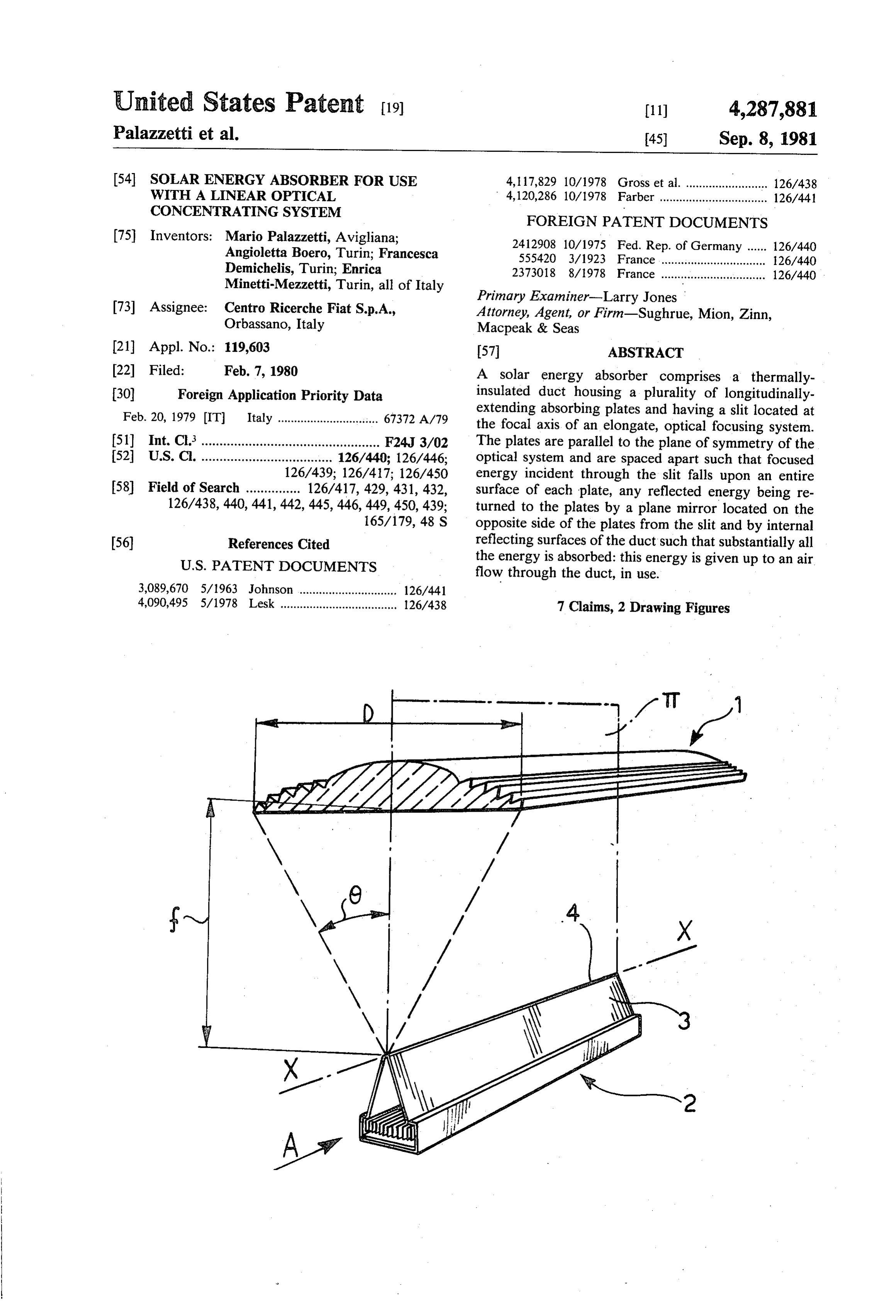
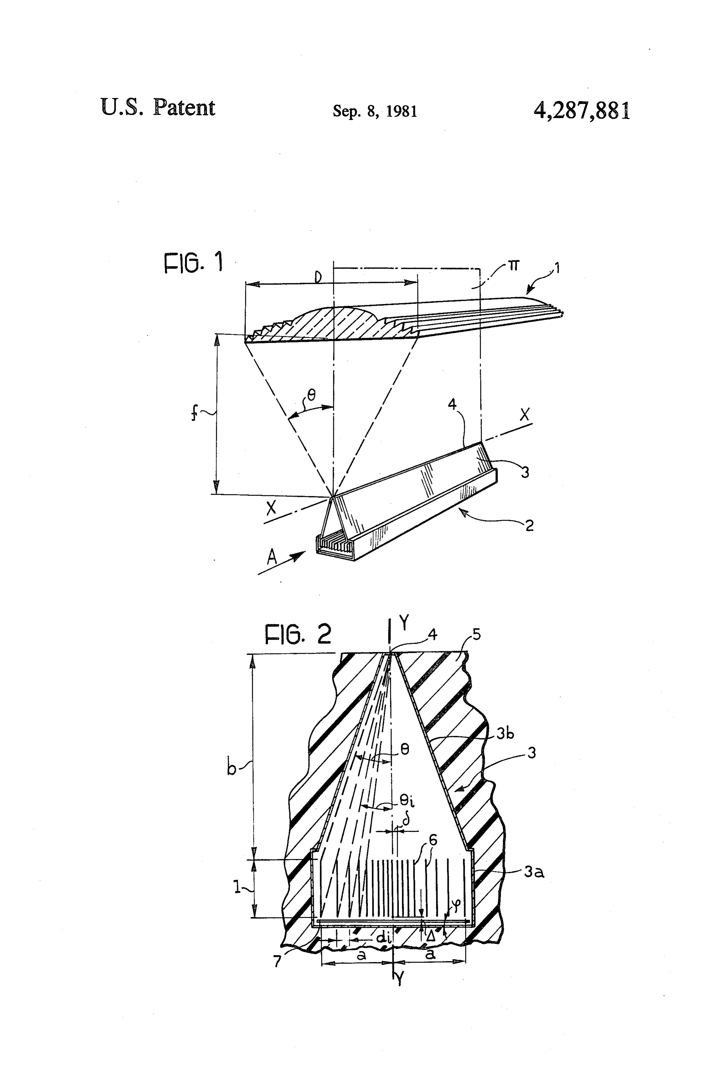
maintenance. Furthermore, it is very difficult to According to a further aspect of the invention there is achieve uniform deposition of the film in the first provided solar energy absorption apparatus comprising instance. 45 an optical system for focusing radiant energy at a focal (d) infra-red radiation emitted by the cylindrical tube axis, in combination with a solar energy absorber as is absorbed by the glass casing and results in heat described above arranged with said slit at the focal axis loss by convection since the glass casing is in direct of the optical system and with the said plates arranged contact with the surrounding air. The use of di parallel to a plane of symmetry of the optical system. chroic deposits on the glass casing to reduce radia 50 tion reflection in the visible range and to increase it BRIEF DESCRIPTION OF THE DRAWINGS in the infra-red range is being studied, but here one One embodiment of the invention will now be more is dealing with techniques which are difficult, particularly described, by way of example, with refer costly and usable in practice only for small casings. ence to the accompanying drawings, in which: (e) given the usual dimensions of the cylindrical ab 55 FIG. 1 is a diagrammatic perspective view of solar sorbing tube, it is extremely difficult to achieve a energy absorption apparatus according to the present steady vacuum between the cylindrical tube and invention, and the glass casing which will limit the heat loss effec FIG. 2 is a cross sectional view of an absorber form tively. ing part of the apparatus of FIG. 1, on an enlarged scale.
DESCRIPTION OF THE PREFERRED
An object of the present invention is to provide a EMBODIMENTS solar energy absorber for use with a linear optical con Referring to FIG. 1 of the drawings, solar energy centrating system which overcomes at least some of the absorption apparatus according to the invention is disadvantages described above and which, in particular, 65 shown including an optical system, generally indicated is technically simple to produce. 1, for focusing radiant energy at a focal axis X-X. In According to the present invention there is provided this embodiment the optical system comprises a Fresnel a solar energy absorber for use with an optical system lens but it may alternatively comprise a cylindrical lens,
Page 4
or a plurality of spherical lenses may be located in a line The mirror 7 is inclined at an anled to a plane perpen so as to concentrate radiant energy at discrete points dicular to the plane of symmetry of the optical system 1. along the focal axis. The angle cb is chosen so as to prevent radiant energy The absorption apparatus further includes a Solar which is incident directly on the mirror 7 adjacent the energy absorber according to the present invention plane of symmetry at of this optical system 1 from being indicated in its entirety as 2, the dimensions of the ab reflected outside the duct 3 through the slit 4. The mir sorber being enlarged compared with those of the opti ror 7 is in fact inclined so as to reflect this portion of the cal system 1 for reasons of clarity. radiant energy on to one of the plates 6 which is located The absorber 2 comprises a duct 3 defined by walls adjacent the plane of symmetry at and hence the angle having reflecting internal surfaces, the duct being sym 10 d) is determined by the equation:
metrical about a longitudinal plane of symmetry coinci dent with a plane of symmetry at of the lens 1 passing through a focal axis X-X.
As best seen in FIG. 2, the duct 3 has a rectangular where A is the distance between the mirror 7 and the channel-section portion 3a and two inclined walls 3b, 15 adjacent edge of one of the plates 6 adjacent the plane of joined each along one longitudinal edge to the free edge symmetry at, and 8 is the perpendicular distance be of a respective side wall of the portion 3a. The walls 3b tween the axis Y-Y and the said one plate 6. are inclined towards each other and have closely The apparatus being made in accordance with the spaced free edges which define between them a slit 4 principles described above, radiant energy focused by located at the focal axis X-X of the lens 1. The slit 4 the optical system 1 at the focal axis X-X and entering thus allows radiation focused at the axis X-X by the the duct 3 through the slit 4 is incident directly on the lens 1, in use, to pass into the duct 3. entirety of one face of each of the plates 6. These plates The duct 3 is provided with an outer jacket 5 of insu lating material which is partially illustrated in FIG. 2. It absorb the greater part of this energy and any small is also provided, within the channel-section portion 3a, 25 portion of the energy which is reflected is returned to with a plurality of similar, spaced-apart plates 6, which the plates 6 by the mirror 7. The reflecting wall surfaces extend longitudinally thereof, parallel to the plane of plates of the duct 3 also reflect energy incident on them to the symmetry at and which are adapted to absorb the radi 6 such that substantially all the radiant energy ant energy which passes into the duct 3 through the slit which enters the duct 3 is trapped and absorbed by the 4. The plates 6 may, for example, be made from bur 30 plates 6.
nished steel. In the use of the apparatus, air is passed through the The relative size and disposition of the various parts duct 3 in the direction of arrow A in FIG. 1 and flows of the apparatus will now be described in greater detail. over the plates 6 to take up the absorbed energy there Referring to FIG. 1, the cross-sectional aperture of from in the form of heat. It is found that the difference the optical system 1 is indicated as D and the focal 35 in temperature between the plates 6 and the air in each length of the system in the plane of symmetry it, that is, conduit formed between two adjacent plates 6 is ex the distance between the focal axis X-X and the opti tremely small but it is advisable to regulate the air flow cal system 1, is indicated as f. The half-aperture angle of in these conduits to avoid the creation of "hot spots' the rays focused at the focal axis X-X of the optical which might occur due to the differing spacings of the system 1 is indicated by 6. 40 plates. The duct 3, however, remains, at substantially In FIG. 2, the trace, in the plane of this Figure, of the ambient temperature.
plane of symmetry at of the optical system 1 is shown as A particular embodiment of the absorption apparatus Y-Y. The distance between the axis Y-Y and the described above has the following dimensions and char absorbing plate 6 which is furthest from this axis is acteristics:
indicated by a. The distance between the upper edges of Optical system 1 the plates 6 and the slit 4, taken along the axis Y-Y, is 45 a cylindrical Fresnel lens having; indicated as b. The distances a and b are such as to allow length = 1 meter;
the plates 6 to capture all the radiant energy which aperture D = 60 cm;
enters the duct 3 through the slit 4. More particularly, a focal length f= 80 cm.
and b are related by the equation: 50 Solar energy absorber 2 a plurality of burnished-steel plates 6 each having;
Furthermore, the spacing di between each pair of height l=3 cm.
adjacent plates 6 is such that none of the plates shades distance b = 10.7 cm.
an adjacent plate from direct radiation from the slit 4; 55 thickness of outer jacket 5 = 5 cm. thus the spacing di of the pairs of adjacent plates varies, a mirror 7 of specular sheet steel. and is calculated for each pair by the formula: In use of the above apparatus of focus solar energy, with a through-flow of air of 150 kg/h, it was found that di-lig0 a rise of temperature of the air by 20 C. degrees could be 60 obtained, starting with air at 20 C., and a usable power where l is the height of the plates 6 parallel to the trace of 200 cal/sec could be generated. Clearly, any number Y-Y and where 0; is the half-aperture angle of the rays of similar pieces of apparatus could be placed in series to which are incident on the upper edge of that plate 6 of generate further usable power, or apparatus using a pair of adjacent plates 6 under consideration, which is longer lenses 1 and corresponding absorbers 2 may be closest to the axis Y-Y. 65 used. In fact, apparatus including a lens 1 having a The duct 3 also houses a longitudinally-extending, length of 25 meters has allowed air temperatures of the plane mirror 7 in the base of the channel-section portion order of 500 C. to be achieved. Apparatus employing a 3a, on the opposite side of the plates 6 from the slit 4. long optical system 1, and correspondingly long duct 3,
Page 5
with a consequent high rise in temperature of the air incident in a direction parallel to said plates onto flow, is also subject to progressively higher heat losses said plates; and along the duct 3, in the direction A of the air flow, by said duct having an air-flow therethrough to take up conduction through the thermally-insulating jacket 5. heat from said plates in use of the absorber. For this reason, the thickness of the jacket 5 is progres 5 2. A solar energy absorber as in claim 1, wherein said sively increased, in the direction of air flow, in appara reflective surface is planar.
tus according to the present having a considerable 3. A solar energy absorber as in claim 1, wherein said length, so as to ensure that this loss by conduction is peripheral wall is provided with an outer jacket of ther substantially constant along the entire length of the duct mally-insulating material.
3. 10 4. A solar energy absorber as in claim 3, wherein the In practice the energy losses of the absorption appa thickness of said outer jacket increases along said duct ratus described above are much smaller than those in the direction of said air-flow therethrough, in use. which occur in apparatus including cylindrical-tube 5. A solar energy absorber as in any preceding claim, type absorbers. More particularly, the energy losses wherein said plates are spaced from each other such which may occur in the absorber according to the in 5 that said radiant energy is incident directly on the entire vention are attributable essentially to three different surface of one face of each said plate. factors: 6. A solar energy absorber as in claim 1, wherein said (a) loss by reflection of radiant energy which is inci peripheral wall has a longitudinally-extending wall por dent on the outer walls of the duct 3 adjacent the 20 tion defining a rectangular-section channel-portion of slit 4. This loss may be reduced, in the embodiment said duct and two planar, inclined wall portions joined illustrated, to a magnitude of the order of 1% of the each along a longitudinal edge to a respective free edge incident radiation, by treating the surfaces adjacent of said wall portion defining said channel portion, said the slit 4 to make them anti-reflecting. inclined wall portions converging to two closely (b) loss of heat through the slit 4 by means of the air 25 spaced longitudinal edges which define said slit, and above the absorber. In the case illustrated, for dif wherein said plurality of parallel, spaced apart plates ferences of temperature of the order of 200° C., this are located within said channel portion of said duct. 7. Solar energy absorption apparatus comprising, in loss is less than 1 cal/sec.
(c) loss of energy by conduction through the outer combination:
jacket 5. For a rise in air temperature of 200 C., the 30 an optical system for focusing radiant energy at a loss due to this factor is less than 10 cal/sec. focal axis, said optical system having a plane of Thus there may be a substantially constant loss of symmetry; and energy of the order of 7% along the entire length of the a solar energy absorber comprising; duct 3. a peripheral wall defining a duct and a longitudinally What is claimed is: extending slit at said focal axis to allow passage of 1. A solar energy absorber for use with an optical 35 said radiant energy focused by said optical system
System for focusing radiant energy at a focal axis, com into said duct, said peripheral wall having a reflec prising; tive internal surface, a peripheral wall defining a duct and a longitudinally a plurality of spaced-apart plates extending longitudi extending slit for location at said focal axis to allow 40 nally within said duct parallel to said plane of sym passage of said radiant energy focused by said opti metry of said optical system, said plates being ar ranged to receive directly said radiant energy pass cal system into said duct, said peripheral wall hav ing through said slit and being adapted to absorb ing a reflective internal surface; said radiant energy as heat;
a plurality of parallel, spaced-apart plates extending a reflective surface extending longitudinally of said longitudinally within said duct, arranged to receive 45 duct on the opposite side of said plates from said directly said radiant energy passing through said slit and being arranged to reflect radiant energy slit and adapted to absorb said radiant energy as incident in a direction parallel to said plates; and heat; said duct having an air-flow therethrough to take up a reflective surface extending longitudinally of said heat from said plates in use of said absorption appa duct on the opposite side of said plates from said 50 ratus.
slit and being arranged to reflect radiant energy k sk k sk
Provenance
- Collection
- Cited prior art
- Original PDF
- patentimages.storage.googleapis.com →
- Filed
- 1980-02-07
- Pages
- 5
- Method
- pdftotext (the PDF's own text layer) + pdftoppm 300dpi page scans
- Source
- Google Patents bibliographic record
- Granted
- 1981-09-08
- Inventors
- Mario Palazzetti; Angioletta Boero; Francesca Demichelis; Enrica Minetti-Mezzetti; Centro Ricerche Fiat SCpA
- Transcribed from
- patentimages.storage.googleapis.com →