patent · US4458653
Vapor fuel system for internal combustion engines
10 July 1984
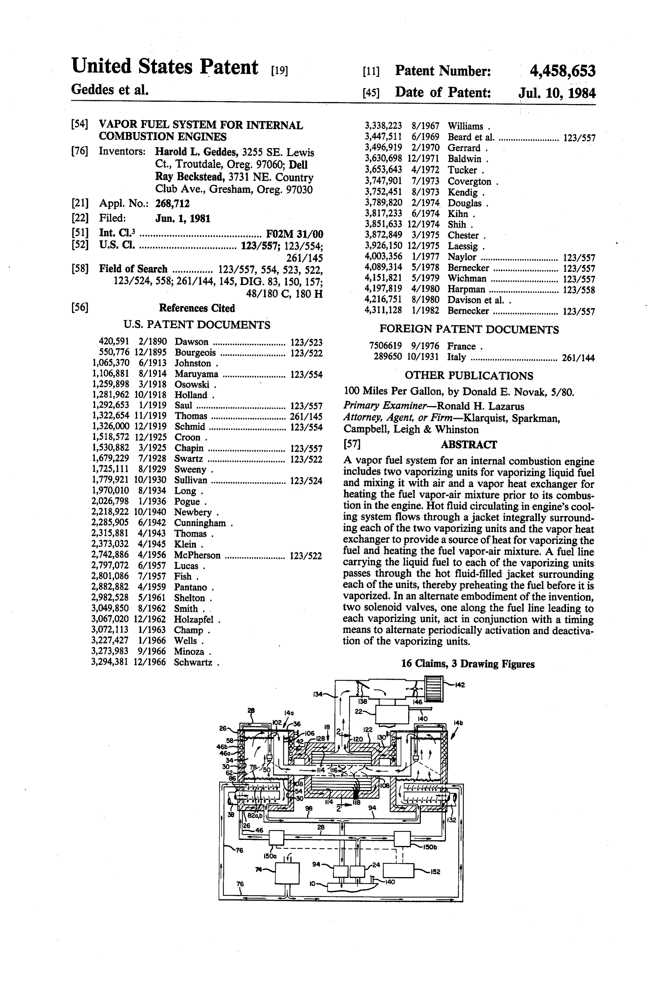
Page 1 — bibliographic record
United States Patent (19) 11) Patent Number: 4,458,653 Geddes et al. 45) Date of Patent: Jul. 10, 1984 (54) VAPORFUEL SYSTEM FOR INTERNAL 3,338,223 8/1967 Williams . COMBUSTON ENGINES 3,447,511 6/1969 Beard et al. ........................ 123/557 76 Inventors: Harold L. Geddes, 3255 SE. Lewis 3,496,919 2/1970 Gerrard . . Ct., Troutdale, Oreg. 97060; Dell 3,630,698 12/1971 Baldwin .
Ray Beckstead, 3731 NE. Country 3,747,901 7/1973 Covergton .
Club Ave., Gresham, Oreg. 97030 3,752,451 8/1973 Kendig.
(21) Appl. No.: 268,712 3,789,820 2/1974 Douglas . (22) Filed: Jun. 1, 1981 3,817,233 6/1974 Kihn .
(51) Int. Cl. ............................................. F02M 31/00 3,872,849 3/1975 Chester . (52) U.S. C. .................................... 123/557; 123/554; 3,926,150 12/1975 Laessig. 261/145 4,003,356 1/1977 Naylor ............................... 123/557 (58) Field of Search ............... 123/557,554, 523, 522, 4,089,314 5/1978 Bernecker ..... ... 123/557 123/524,558; 261/144, 145, DIG. 83, 150, 157; 4,151,821 5/1979 Wichman ...... ... 123/557 48/180 C, 180 H 4,197,819 4/1980 Harpman ............................. 123/558
(56) References Cited 4,311,128 1/1982 Bernecker ........................... 123/557
420,591 2/1890 Dawson .. ... 123/523 7506619 9/1976 France .
550,776 12/1895 Bourgeois 123/522 289650 10/1931 Italy .................................... 261/144
1,106,881 8/1914 Maruyama .......................... 123/554 OTHER PUBLICATIONS
1,281,962 10/1918 Holland . 100 Miles Per Gallon, by Donald E. Novak, 5/80. 1,292,653 1/199 Saul ..................................... 123/557 Primary Examiner-Ronald H. Lazarus 1,322,654 11/1919 Thomas ... ..., 261/145 Attorney, Agent, or Firm-Klarquist, Sparkman, 1,326,000 12/1919 Schmid .... ... 123/554 Campbell, Leigh & Whinston
1,530,882 3/1925 Chapin ................................ 123/557 (57) ABSTRACT 1,679,229 7/1928 Swartz ............................... 123/522 A vapor fuel system for an internal combustion engine 1,725,111 8/1929 Sweeny . includes two vaporizing units for vaporizing liquid fuel 1,779,921 10/1930 Sullivan ............................... 123/524 and mixing it with air and a vapor heat exchanger for 1,970,010 8/1934 Long. heating the fuel vapor-air mixture prior to its combus 2,026,798 1/1936 Pogue . tion in the engine. Hot fluid circulating in engine's cool 2,218,922 10/1940 Newbery . ing system flows through a jacket integrally surround
2,315,881 4/1943 Thomas . ing each of the two vaporizing units and the vapor heat 2,373,032 4/1945 Klein . exchanger to provide a source of heat for vaporizing the 2,742,886 4/1956 McPherson ........................ 123/522 fuel and heating the fuel vapor-air mixture. A fuel line 2,797,072 6/1957 Lucas . carrying the liquid fuel to each of the vaporizing units 2,801,086 7/1957 Fish . passes through the hot fluid-filled jacket surrounding 2,882,882 4/1959 Pantano . each of the units, thereby preheating the fuel before it is 2,982,528 5/1961 Shelton . vaporized. In an alternate embodiment of the invention, 3,049,850 8/1962 Smith . . two solenoid valves, one along the fuel line leading to 3,067,020 12/1962 Holzapfel . each vaporizing unit, act in conjunction with a timing 3,072,113 1/1963 Champ . means to alternate periodically activation and deactiva 3,227,427 1/1966 Wells. tion of the vaporizing units.
3,294,381 12/1966 Schwartz . 16 Claims, 3 Drawing Figures
Page 2
Drawing sheet — no readable text.
Page 3
vaporize the fuel and start the engine. As a result, a
WAPORFUEL SYSTEM FOR INTERNAL conventional liquid fuel system must be used to start COMBUSTON ENGINES and warm up the engine, even when the engine has been shut off for only a few minutes.
BACKGROUND OF THE INVENTION 5 Finally, while vapor systems generally achieve a 1. Field of the Invention shorter, more complete and less wasteful burn of the The present invention relates generally to fuel sys fuel than liquid fuel systems, the fuel-air mixture com tems for internal combustion engines and more particu busted is inherently leaner. Thus, vapor systems, such as larly to a method and apparatus for supplying a vapor 10 those discussed above, generally cannot generate as ized fuel to an internal combustion engine. much power as liquid systems. The power output of the 2. Description of the Prior Art vapor system can be increased by supplementing the Fuel vapor systems which supply fuel vapor to an fuel vapor with liquid fuel, but then the overall fuel internal combustion engine are old in the art. Such efficiency is reduced.
systems are generally more fuel efficient than conven 15 Accordingly, there is a need for a fuel vapor system tional liquid fuel systems because they deliver more which reduces the amount of unvaporized fuel in the spaced and uniformly spread fuel molecules to the com vaporization chamber, reduces the amount of fuel vapor bustion chamber, thereby promoting a shorter, more condensation, is capable of starting and running the complete and hence, more efficient burn of the fuel. engine without the help of a supplementary fuel system Typical fuel vapor systems are disclosed in a number 20 shortly after the engine is shut off, and produces suffi of U.S. patents, including Davison, et al. U.S. Pat. No. cient vapor to satisfy the power requirements of the 4,216,751; Champ, U.S. Pat. No. 3,072,113; Cunning engine under most conditions in a fuel efficient manner.
No. 2,882,882, and Long, U.S. Pat. No. 1,970,010. In SUMMARY OF THE INVENTION each of these systems raw liquid fuel is vaporized in a The present invention solves the foregoing problems vaporization chamber heated by exhaust gases dis 25 and improves prior art fuel vapor systems by providing charged from the engine. The fuel vaporis subsequently two selectively operable fuel vaporizing units in parallel mixed with most, if not all, of the air needed for com fluid communication with a fuel tank and an internal bustion and delivered to the engine. combustion engine. Liquid fuel is pumped from the fuel These systems have a number of disadvantages. With tank the possible exception of Long, each of the above sys passestothrough 30 each vaporizing unit through a fuel line which tems delivers liquid fuel at or close to ambient tempera porizing unit anda isfluid-filled jacket surrounding the va ture to the vaporization chamber. Since the temperature of the unit. Hot fluid circulating awithin sprayed into vaporization chamber of the fuel must be increased substantially to its vapori of the engine flows through each jacketaand cooling system thoroughly zation temperature before vaporization will occur, a preheats the fuel in the fuel line, thereby increasing the considerable amount of heat must be supplied. As a 35 temperature of the fuel significantly and minimizing the result, a significant percentage of the fuel delivered to the vaporization chamber never vaporizes and must be amount of fuel which subsequently fails to vaporize. either returned to the fuel tank or delivered to the en Moreover, the hot fluid retains its capacity to generate gine in liquid form, thereby reducing the fuel efficiency heat for quite some time after the engine is shut off, of the system. The Long system apparently preheats the 40 thereby allowing the engine to be started with the fuel liquid fuel in a primary heater pipe, but the amount of vapor system when the engine is still warm. heat supplied appears to be minimal and not enough to As the fuel is vaporized within the vaporization alleviate the problem. chamber it is mixed with a full supplement of air, In each of the above systems, it is also quite likely that thereby eliminating the condensation problem caused a significant percentage of the fuel vapor cools and 45 by adding air after the fuel is vaporized. The fuel vapor condenses as it travels from the vaporization chamber air mixture is heated in a vapor heat exchanger having to the engine, since the fuel vapor is at a temperature a baffle for directing the mixture in a generally spiral not much above its condensation temperature and little path within the heat exchanger. Heat is supplied to the is done to prevent heat loss, other than perhaps insulat heat exchanger by hot fluid flowing through a jacket ing the fuel vapor line or making the line as short as 50 surrounding the baffle. The heat exchanger serves to possible. Such condensation also reduces the fuel effi not only minimize condensation of the fuel vapor, but to ciency of the fuel vapor system. The condensation prob positively increase the temperature of the fuel vapor-air lem is compounded in Davison, Cunningham and mixture, thereby further increasing the fuel efficiency of Champ where a full supplement of air at or close to the system. The heated mixture is directed through a ambient temperature is mixed with the fuel vapor 55 carburetor to the engine where it is combusted. shortly before combustion, thereby cooling and con In an alternate embodiment of the invention, two densing even more of the vapor. The Pantano and Long solenoid valves are used in conjunction with a timing vapor systems introduce a small quantity of air into the mechanism to enable the vaporizing units to be acti vaporization chamber to mix with the fuel while it is vated and deactivated periodically, so as to increase the being vaporized. However, this alleviates the problem maximum power output of the engine in a fuel efficient to only a slight extent since most of the air is mixed with ac.
the fuel after it has been vaporized. It is therefore one object of the invention to provide Additionally, the exhaust gases used by the above an improved vapor fuel system for an internal combus systems to vaporize the fuel dissipate rapidly after the tion engine of simplified, low-cost construction. engine is shut off, thereby causing the manifold and 65 Another object of the invention is to provide an im exhaust pipes carrying the exhaust gases to cool down proved fuel vapor system, as aforesaid, which can be rapidly. Thus, once the engine is shut off the above used in conjunction with a liquid fuel system of the systems are incapable of supplying sufficient heat to engine.
Page 4
A further object of the invention is to provide a fuel A fuel pump 24, preferably of the fixed-displacement vapor system, as aforesaid, which can be easily and type, pumps liquid fuel from the fuel tank 10 through a practically installed so as to convert an internal combus hollow, cylindrical jacket 26 via a fuel line 28 to the tion engine from one which runs primarily on liquid fuel vaporizing unit 14a, where the fuel is vaporized. to one which runs primarily on fuel vapor. The vaporizing unit has a cylindrical wall 30 that An additional object of the invention is to provide a defines a vaporization chamber 34 and is integrally vapor fuel system of compact, simplified construction surrounded on all but the top sides by the jacket 26. A which can be economically and practically installed and removable lid 36 is secured to the vaporizing unit to seal used with conventional motor vehicle engines. the vaporization chamber.
A still further object of the invention is to provide a 10 The jacket is filled with a hot fluid, typically water, fuel vapor system in which the liquid fuel is thoroughly from a liquid cooling system of the engine. The hot fluid preheated prior to its vaporization. enters the jacket through an intake port 38, flows Another object of the invention is to provide a fuel outlet portthe42,jacket, through and exits the jacket through an thereby providing the jacket with a con vapor system which increases the fuel efficiency of the 15 tinuous influx of hot fluid. engine with which it is used. The jacket serves a two-fold purpose. It serves to A further object of the invention is to provide a fuel heat wall 30 and vapor system which is adapted to be used with conven preheat the fuel inchamber 34, and also to thoroughly fuel line 28 as it passes through the tional liquid fuel supply systems of internal combustion jacket. It has been found that if the line 28 within the engines. 20 jacket is coiled around wall 30 several times, such as at Yet another object of the invention is to provide a fuel vapor system in which a substantial amount of air is 46a can and 46b, and is formed from copper tubing, gasoline be substantially preheated to at least 125 F., a tem mixed with the liquid fuel as it is being vaporized.
A further object of the invention is to provide a fuel the fuel substantially perature above its ambient temperature in vapor system which minimizes condensation of the fuel 25 greatly minimizes the amount preheating tank. Such thorough of fuel of the fuel which fails to after it has been vaporized. vaporize in the vaporization chamber as compared to An additional object of the invention is to provide a fuel vapor system in which means for efficiently heating prior fuel vapor systems.
After the preheated fuel in line 28 leaves the jacket, a the fuel vapor-air mixture is provided. nozzle 50 atomizes and sprays the fuel into the chamber Yet another object of the present invention is to pro 30 34 and against a portion of wall 30 disposed between vide a system in which a common heat source is used to two horizontal, vertically-spaced screens, a first lower preheat and vaporize the fuel and to heat the fuel vapor screen 54 and second upper screen 58. after it is mixed with air. Because the intake port 38 is located near the bottom An additional object of the invention is to provide a of the jacket, the hot fluid entering the jacket heats the system in which circulating hot fluid from the engine's 35 lower portion of wall 30 to a slightly higher tempera cooling system is used as a heat source. ture than the upper portion. Since much of the fuel Another object of the invention is to provide a system vaporizes upon striking the wall, it is desirable to spray that has two vaporizing units which can be activated the fuel against the lowest possible portion of the wall selectively and alternated periodically. above screen 54, such as at 62. In this regard, it has been Other objects and advantages of the invention will found that where the nozzle is centrally located within become apparent from the following detailed descrip the chamber, a nozzle having a 70 spray angle works tion and with reference to the accompanying drawings. well.
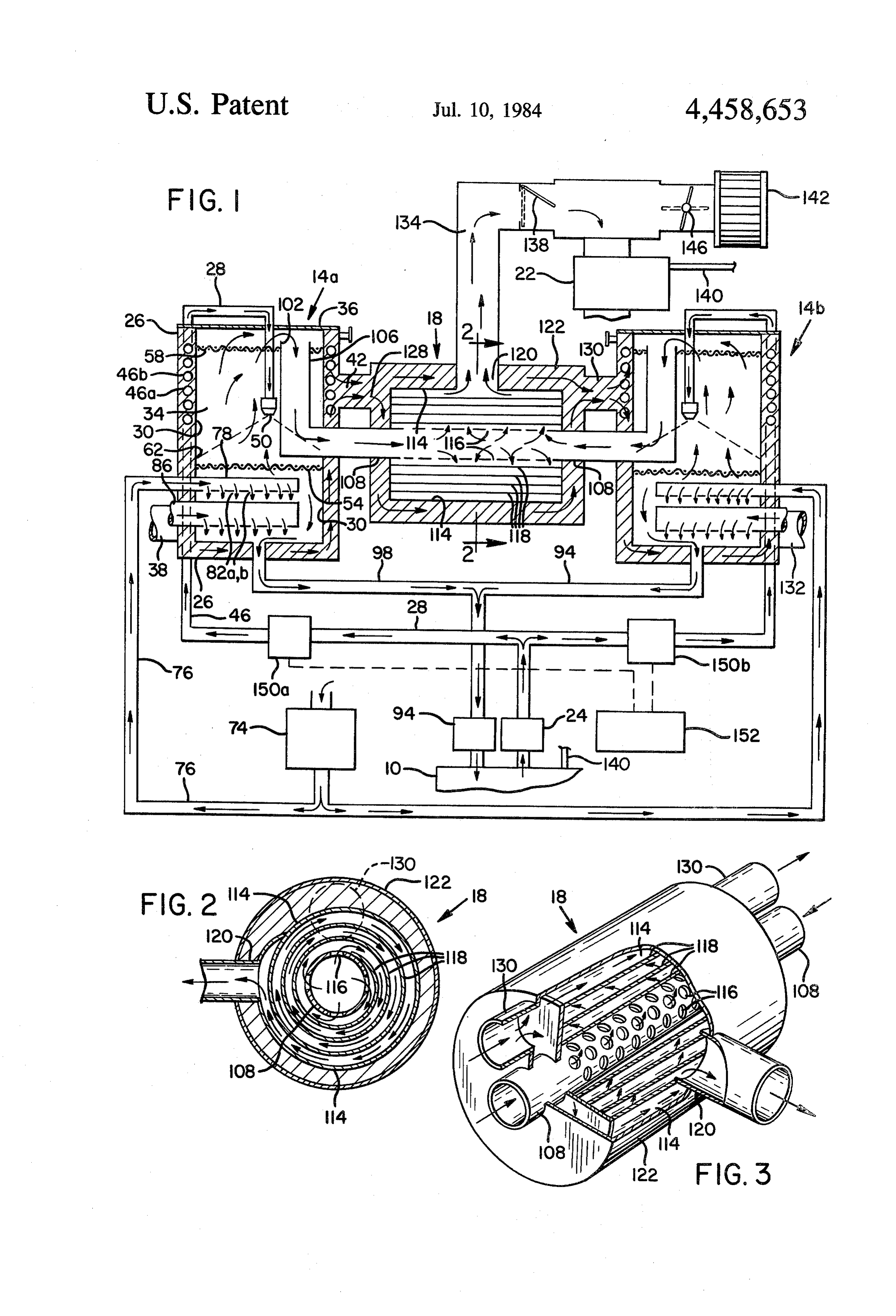
BRIEF DESCRIPTION OF THE DRAWING As the fuel is being vaporized within the vaporization chamber, an air pump 74 introduces charged air into a
In the drawings: 45 lower portion of the chamber below screen 54 through FIG. 1 is a generally sectional view of a fuel vapor a charged air line 76. So as to minimize turbulence system in accordance with the present invention. within the chamber, a series of holes or orifice means FIG. 2 is an enlarged cross-sectional view of a vapor along the underside of an end 78 of air line 76, such as heat exchanger taken along line 2-2 of FIG. 1. at 82a, b, temporarily directs the air in a downward FIG. 3 is an enlarged perspective view of the vapor 50 direction away from the main portion of chamber 34 heat exchanger with a portion of its outer surface cut before the air passes through screen 54 and mixes with away. the vapor. The screen 54 serves as a collection point for DETAILED DESCRIPTION OF A PREFERRED unvaporized fuel and to preheat the air before it mixes
55 By introducing charged air into the vaporization
As shown in FIG. 1, the present invention preheats chamber, the fuel vapor is mixed with virtually all the liquid fuel drawn from a fuel tank 10 and vaporizes the air needed for combustion in the chamber and the air fuel in two fuel vaporizing units 14a and 14b, During and fuel vapor are able to reach an equilibrium tempera vaporization the fuel is mixed with preheated air. The ture within the chamber that is above the vaporization resulting fuel vapor-air mixture from each vaporizing temperature of the fuel. Hence, it is not necessary to add unit is heated in a common vapor heat exchanger 18 and "cool' air to the fuel vapor in the carburetor, thereby delivered to a carburetor 22 of an internal combustion condensing some of the vapor, as is done with prior fuel engine. vapor systems.
A more detailed description of the present invention Where a conventional smog pump, such as that found will be given with reference to the vaporizing unit 14a. 65 on many automobiles, is used as the air pump 74 and the It will be understood, however, that the vaporizing unit charged air line 76 has a diameter of one half inch, a 14b is a mirror image of its counterpart in both opera sufficient amount of air can be supplied to the vaporiz tion and design. ing unit for most operating conditions. The amount of
Page 5
air admitted into chamber 34 is determined to a certain stream pressure surge or flow along line 134, such as extent by the number and size of the holes on end 78. If might be caused by a backfire of carburetor 22. additional air is required, such as under high power While the present invention can be used with many conditions, air at atmospheric pressure can be intro different types of internal combustion engines, it is par duced into the chamber through an air line 86. The ticularly adapted to be used with engines having a con amount of atmospheric air introduced into the chamber ventional fuel supply system, such as automobile en is controlled by abutterfly valve (not shown) along line gines. The rudiments of a conventional fuel system are 86. As with charged air line 76, such air is introduced shown in FIG.1. The conventional fuel system includes into the chamber through a series of holes along the a fuel line 140 in fluid communication with fuel tank 10 underside of air line 86 so as to minimize turbulence O and carburetor 22, a fuel pump (not shown), an air filter within the chamber. Airline 86 preferably has a diame 142 and a butterfly valve 146. When the conventional ter of one inch. system is active, the vapor system is bypassed by deliv Fuel which does not vaporize in the vaporization ering fuel directly from the fuel tank to the carburetor chamber or which vaporizes and then condenses col through the line 140. Air is drawn through an air filter lects on screens 54 and 58 and drains to the bottom of 15 142 and a butterfly valve 146 and mixed with the fuel in the chamber where a fuel return pump 94 pumps the the carburetor in a conventional manner. While pumps excessfuel through a fuel returnline 98back to fuel tank 24 and 94 are inactive, pump 74 remains active and 0. provides a small amount of heated air to the carburetor Normal suction developed by the engine causes the through line 134 and valve 138. The vapor system is fuel vapor-air mixture to pass through screen 58 and activated by closing a solenoid valve along line 140, into a vapor intake port 102 which directs the mixture thereby stopping the flow of liquid fuel to the carbure to a fuel vapor line 106 leading to heat exchanger 18. tor, and activating pumps 24 and 94. The valve 138 will The screen 58 helps prevent raw fuel from entering automatically open further in response to increased intake port 102. The position of the intake port such that pressure in line 134.
it opens in a direction generally opposite the direction 25 In operation, the conventional fuel system is used to of spray of nozzle 50 also helps prevent raw fuel from initially start the engine and heat the engine's coolant entering the intake port. fluid to a temperature sufficient to vaporize the fuel. The mixture enters the heat exchanger through an This normally takes about five minutes, after which line intake tube 108 extending axially therethrough and is 140 is closed and the vapor system activated. dispelled through an orifice means into a heating cham 30 However, the conventional fuel system is not needed ber defined by an inner wall 114 of the heat exchanger, to start the engine where the engine has been running As shown in FIG. 3, the orifice means includes a series and then shut off for a short period of time, since the hot of uniformly spaced holes, such as at 116. A spiral fluid in jacket 26 will still be hot enough to vaporize the shaped baffle 118 within inner wall 114, as shown in fuel. Hence, under these conditions, the fuel vapor sys FIGS. 2 and 3, directs the mixture in a generally spiral 35 tem can be used to start the engine, unlike prior vapor path through the heating chamber from the orifice systems. Moreover, it will be understood that the pres means to a vapor outlet port 120. ent invention can be used as the sole fuel supply system The mixture is heated as it travels through baffle 118 as long as some other means of initially heating the by heat supplied by a hollow, fluid-filled, cylindrical engine's cooling fluid to a temperature sufficient to heat-exchanger jacket 122 which integrally surrounds vaporize the fuel is provided.
wall 114 on all sides. Hot fluid exiting the outlet port 42 While the present invention will run in a satisfactory of jacket 26 enters the heat exchanger jacket through a manner with one vaporizing unit, it is desirable to use first port 128, flows through the heat exchanger jacket two vaporizing units, such as shown in FIG. 1, which and exits the jacket at a second port 130. Heat is trans can each be activated and deactivated selectively. The ferred from the hot fluid to wall 114 and baffle 118, both 45 units are activated and deactivated selectively by open of which are preferably made of copper sheet, thereby ing and closing two solenoid valves 150a and 150b, one heating the heating chamber and the fuel vapor-air each disposed along the fuel line 28 leading to vaporiz mixture as it passes therethrough. The heat supplied to ing units 14a and 14b. Under normal conditions, one the mixture serves not only to minimize condensation of unit is active and the other dormant. If more power the fuel vapor prior to its delivery to the engine, but also 50 from the engine is required, the second unit can be to positively increase the temperature of the mixture activated temorarily to supply additional fuel vapor to significantly to further increase the fuel efficiency of the the engine. While more fuel is consumed when both system. When the fuel used is gasoline, it has been found units are activated, it is consumed in a fuel efficient that the heat exchanger 18 heats the fuel vapor-air mix manner and without resort to the use of liquid fuel. It ture to a temperature of at least 145 F. 55 will be understood that more than two vaporizing units The hot fluid exits the heat exchanger through the can be used with the present invention, although in such second port 130 and enters the jacket of second vaporiz an embodiment it may be impractical to use a common ing unit 14b, where it preheats and vaporizes the fuel vapor heat exchanger.
supplied thereto. The fluid then exits the jacket through With regard to the vaporizing units, it has been found an exit port 132, which is in fluid communication with a that a nozzle 50 having a flow rate of 1.5 gallons per means for cooling and recirculating the fluid, such as a hour will adequately atomize.the fuel when it is sprayed radiator and pump commonly associated with most into the chamber 34, Further, it is necessary that the automobile engines, pump 24 be of a high pressure type capable of develop The vapor outlet port 120 directs the heated mixture ing 30-60 psi in order to force the fuel through the throughjacket 122 and to a line 134 which delivers the 65 nozzle, mixture to carburetor 22. However, before the mixture In an alternate embodiment of the invention, a timing is delivered to the carburetor, it passes through a one means 152 is used to open and close the solenoid valves way check valve 138 which acts to prevent any up 150a and 150b periodically so that one vaporizing unit is
Page 6
active while the other is dormant and vice versa. In this 5. A vaporizing means according to claim 3 including way, the power output of the engine is increased in a fuel return passage means in fluid communication with fuel efficient manner because the dormant vaporizing said chamber for draining liquid fuel from the bottom of unit continues to provide residual fuel vapor left over said chamber.
from when it was active to the engine for a period of 5 6. A vaporizing means according to claim 1 including time after it becomes dormant. When the residual fuel an air supply means in fluid communication with said vapor in the dormant vaporizing unit begins to dissi vaporizing means and operable to introduce air into said pate, typically after 15-20 seconds, the timing means vaporizing means to mix with fuel therein during the activates the dormant vaporizing unit and deactivates vaporization of the liquid fuel.
the active vaporizing unit. Any conventional timing 10 7. A vaporizing means according to claim 1 wherein means for periodically opening and closing valves 150a an engine coolant fluid is passed along an outside sur and 150b, such as a timer having a free-running, variable face of said wall means to heat said chamber. frequency multivibrator circuit which generates im 8. A fuel supply system for an internal combustion pulses to trigger the valves, can be used. engine in which the system is provided with a source of While the present invention is particularly adapted to 15 liquid fuel, the system comprising: be used with an internal combustion engine having a a fuel vaporizing means including an enclosed vapor liquid cooling system, such a cooling system is not re izing chamber and chamber heating means for quired. Alternatively, the present invention can be used heating said vaporizing chamber to facilitate the with air-cooled engines simply by using the hot exhaust vaporization of fuel introduced into said chamber gases produced by the engine as a heat source to preheat 20 from a first passage means; and vaporize the liquid fuel and to heat the fuel vapor a liquid fuel heating means for preheating the liquid air mixture. fuel in said first passage means before it is intro Having illustrated and described the principles of our duced into said vaporizing chamber, invention by what is presently a preferred embodiment said first passage means being in fluid communication and several suggested alternatives, it should be apparent 25 with said source and vaporizing chamber and in to those persons skilled in the art that such embodiments cluding a passage portion for conveying liquid fuel may be modified in arrangement and detailed without along a tortuous path through said liquid fuel heat departing from such principles. We claim as our inven ing means, said first passage means terminating at a tion all such modifications as come within the true spirit fuel spray nozzle means within said chamber; and scope of the invention as defined by the following 30 air supply means in fluid communication with said claims. chamber and operable to introduce air into said We claim: chamber to mix with fuel therein as such fuel is 1. In a fuel vaporizing system for supplying a vapor being vaporized;
ized fuel to an internal combustion engine in which the second passage means in fluid communication with system is provided with a source of liquid fuel and pas 35 said chamber for conveying a fuel vapor-air mix sage means for conveying liquid fuel from said source to ture from said chamber toward said engine, and a vaporizing means for vaporizing the liquid fuel, a vapor heating means for heating said fuel vapor-air vaporizing means comprising: mixture downstream of said chamber, said second wall means defining a vaporization chamber, passage means passing through said vapor heating nozzle means at the downstream end of said passage 40 means;
means for spraying the liquid fuel in a generally said chamber heating means and said liquid fuel heat downward direction against sidewall portions of ing means comprising a common heating means; said wall means within said chamber; and said air supply means including pump means for in fluid-filled jacket means surrounding said vaporiza troducing charged air into said chamber and sec tion chamber to heat said chamber and vaporize 45 ond air supply means for selectively introducing liquid fuel introduced into said chamber by said additional quantities of air at atmospheric pressure nozzle means; into said chamber;
said passage means following a tortuous path through said air supply means including orifice means within said jacket means to preheat the liquid fuel before it said vaporizing means for temporarily directing enters said chamber. 50 said charged air and air at atmospheric pressure 2. A vaporizing means according to claim 1 wherein away from the central portion of said chamber as it said nozzle means is positioned within said chamber so enters said chamber, said orifice means being dis as to spray said liquid fuel against sidewall portions of posed nearer the bottom than top of said chamber. said wall means nearer the bottom than top of said 9. A method of fueling an internal combustion engine chamber. 55 with a fuel vapor-air mixture comprising: 3. A vaporizing means according to claim 2 including preheating a liquid fuel, a vapor intake port within said vaporization chamber vaporizing the preheated liquid fuel, for receiving the vaporized fuel and directing it toward mixing the fuel vapor with air, said engine, said vapor intake port being disposed adding heat to the vapor-air mixture, nearer the top than bottom of said vaporization cham the preheated liquid fuel being vaporized by atomiz ber and opening generally away from the central por ing the preheated liquid fuel in the presence of air tion of said vaporization chamber. within a chamber heated to a temperature sufficient 4. A vaporizing means according to claim 3 including to vaporize said liquid fuel such that the fuel vapor two horizontal, vertically-spaced liquid fuel-collecting and air mix within said chamber; screens within said vaporization chamber, one of said 65 the preheated liquid fuel being vaporized and mixed screens being disposed below said nozzle means and the with air by spraying the liquid fuel into the cham other above said nozzle means and below said intake ber in a generally downward direction, introducing port. air into the chamber, and screening the air in the
Page 7
chamber to preheat the same before it mixes with a liquid fuel heating means for preheating the liquid the fuel vapor, fuel in said first passage means before it is intro draining excess liquid fuel from the bottom of the duced into said vaporizing chamber, chamber, said first passage means being in fluid communication drawing off a fuel vapor-air mixture from the upper with said source and vaporizing chamber and in end of said chamber after screening the mixture to cluding a passage portion for conveying liquid fuel collect unvaporized fuel, and along a tortuous path through said liquid fuel heat ing means, said first passage means terminating at a delivering the fuel vapor-air mixture to the internal fuel spray nozzle means within said chamber; combustion engine. 10 air supply means in fluid communication with said 10. The method of claim 9 wherein heat is added to chamber and operable to introduce air into said the vapor-air mixture by passing the mixture in a gener chamber to mix with fuel therein as such fuel is ally spiral path through a heat exchanger. being vaporized;
11. The method according to claim 9 wherein the second passage means in fluid communication with heat required to heat the fuel medium is supplied by 15 said chamber for conveying a fuel vapor-air mix passing the fuel medium in a heat exchange relationship ture from said chamber toward said engine, and to a hot coolant fluid from the engine's coolant system. vapor heating means for heating said fuel vapor-air mixture downstream of said chamber, said second 12. The method of claim 9 wherein the liquid fuel is passage means passing through said vapor heating preheated to a temperature of at least about 125 F. 20 means;
13. The method of claim 9 wherein the chamber is said chamber heating means and said liquid fuel heat heated to a temperature of at least 125 F. ing means comprising a common heating means; 14. The method of claim 9 wherein the vapor-air said chamber heating means and liquid fuel heating mixture is heated to a temperature of at least 145 F. means comprising a first jacket means in surround before delivering it to the engine. 25 ing relationship to the vaporizing chamber, said 15. A fuel supply system for an internal combustion passage portion forming a coil within said first engine in which the system is provided with a source of jacket means to cause the fuel to follow a generally liquid fuel, the system comprising: helical path through said first jacket means. 16. A fuel supply system according to claim 15 a fuel vaporizing means including an enclosed vapor 30 wherein izing chamber and chamber heating means for within a second said second passage means includes means jacket means for causing the fuel vapor heating said vaporizing chamber to facilitate the air mixture to follow a generally spiral path through vaporization of fuel introduced into said chamber said second jacket means.
from a first passage means; a
Provenance
- Collection
- Cited prior art
- Original PDF
- patentimages.storage.googleapis.com →
- Filed
- 1981-06-01
- Pages
- 7
- Method
- pdftotext (the PDF's own text layer) + pdftoppm 300dpi page scans
- Source
- Google Patents bibliographic record
- Granted
- 1984-07-10
- Inventors
- Harold L. Geddes; Dell Ray Beckstead
- Transcribed from
- patentimages.storage.googleapis.com →