patent · US2742886
Fuel generator for internal combustion engines
24 April 1956
Page 1
Drawing sheet — no readable text.
Page 2
United States Patent Office 2,742,886 Patented Apr. 24, 1956
pipe 20 through the gasoline at a supply level 25.
or liquid fuel 24 maintained 2,742,886 The liquid fuel supply is kept at the desired level 25
FUEL COMBUSTION
GENERATOR FOR INTERNAL
ENGINES
by suitable fuel pump 26 which withdraws gasoline through the line 27 from the gasoline tank 28 and dis charges it through the line 29 into a sight gage 30 for in
Carl W. McPherson, Phoenix, Ariz., assignor of forty-nine dication per cent to Solomon P. Scholl of the correct level of the liquid fuel supply at the line 25. Suitable means may be used for controlling
Application November 1, 1954, Serial No. 466,085 O the fuel pump 26 to maintain this level such as a return 4 Claims. (CI. 123-133) drain line 3 or a float level control for the fuel pump 26 (not shown). Thus at all times the proper level of liquid fuel under all operating conditions is maintained at the level 25 in the fuel generator 10.
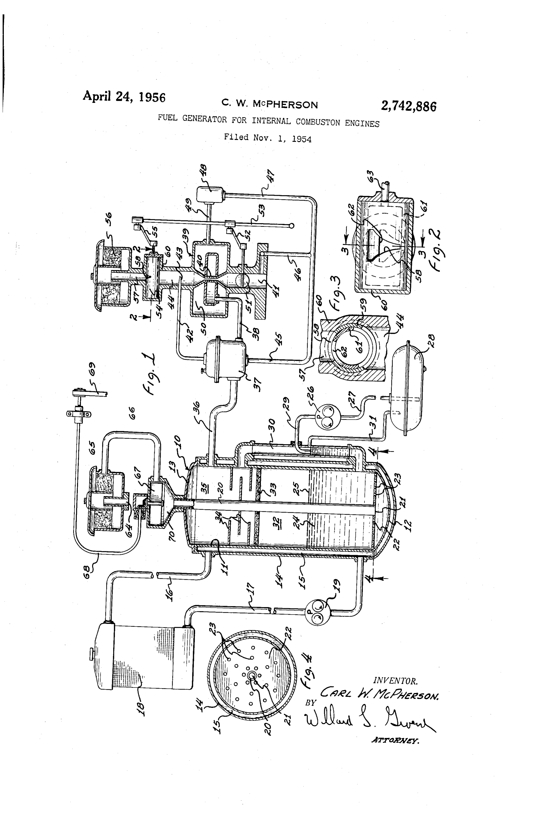
This invention pertains to improvements in fuel gen As the air coming up through the perforations 23 in erators for internal combustion engines and is particularly 5 the baffle 22 percolates up through the liquid fuel 24 adapted to the preparation of dry gas fuel for an internal it escapes finally at the top surface 25 of the liquid into combustion like.
engine directly from liquid gasoline or the the chamber portion 32 of the generator in the form of a gaseous mixture of air and fuel. A suitable gauze baffle
One of the objects of this invention is to provide means 20 33 and labyrinth baffle 34 remove any droplets of liquid for converting liquid fuels to a combination of gas and fuel in the gaseous mixture as it continues to rise into air mixture for presentation to an internal combustion the final dry gas chamber 35 of the fuel generator. engine. The dry gas then discharges from the chamber 35 Still another object of this invention is to provide an through a line 36 through the dry gas inlet regulator 37 improved fuel generator capable of converting liquid 25 and then out through the line 38 to the gas carburetor 39 fuels to gaseous mixtures with air for presentation to of the internal combustion engine, the dry gas from the internal combustion engines to improve the efficiency, op line 38 passing through the usual venturi inlet opening eration, of and cut down maintenance cost in the operation such engines. 40 to the passageway 41 connected to the intake manifold of the internal combustion engine. A suitable line 42
Still another object of this invention is to provide an 30 connected to the dry gas regulator 37 and terminating improved fuel generator for an internal combustion en in the Pitot tube 43 in the intake passageway 44 of the gine including a generating tank for converting liquid dry gas carburetor 39 provides means for controlling the gasoline or the like to a dry gas mixture of air and gas diaphragm of the dry gas inlet regulator 37. The dia and to present such dry gas mixture through a gas car phragm in the dry gas inlet regulator 37 is also con buretor to an internal combustion engine. 35 trolled through vacuum applied through the line 45 Still another object of this invention is to provide an connected through line 46 to the passageway 4 of the improved fuel system for an internal combustion engine carburetor which allows dry gas to enter directly through including a device for converting the liquid fuel to a the line 47 and the by-pass valve 48 and line 49 into gas. and air mixture and to present the said mixture to the chamber 50 for applying gas directly into the engine the internal combustion engine while feeding additional 40 for rapid pickup and acceleration in a well known con air tothetheengine.
mixture as it is presented through the carburetor tion,ventional manner forming no specific part of this inven into
A further object of this invention is to provide an im The butterfly valve 5 for speed control of the internal proved dry gas-air mixture generator for particular use combustion engine is actuated by suitable linkage 52 in conjunction with internal combustion engines. 45 from the throttle control rod 53 to which is also connected Further features and advantages of this invention will the air inlet control valve indicated at 54 through suit appear from a detailed description of the drawings in able linkage 55 connected to the throttle control rod which: 53. This valve 54 receives an intake atmospheric air Fig. 1 is a schematic diagram showing the fuel gen supply through a suitable air cleaner 56 which is con erator System for internal combustion engines incorporat 50 nected through the passageway 57 to the proportional air ing the features of this invention. control slot 58 which varies the air input supply in proper Fig. 2 is an enlarged view on the line 2-2 of Fig. 1 proportion to the normal speed of the internal combus showing the air inlet control for the engine carburetor. tion engine. The outside cylinder member 59 containing Fig. 3 is a section on the line 3-3 of Fig. 2. the slot 58 is fixed in the housing 60 having the passage Fig. 4 is a section on the line 4-4 of Fig. 1. 55 ways 44 and 57. Inside of the outside cylindrical member As an example of one embodiment of this invention, is the inside member 6 having a cooperating mating there is shown in Fig. 1 the fuel generator indicated gen proportioning slot 62. Both of the inside and outside erally at 10 which comprises a vertically disposed inner cylindrical members are in communication with the inlet cylindrical member 1 having a closed bottom 12 and a passageway 44 of the gas carburetor 39. The inside cover 13 for the top. A suitable water jacket 14 having 60 cylindrical member 61 is rotated through a shaft 63 con the chamber 15 is connected through suitable piping 16 nected to the linkage 55 of the throttle control rod 53 for and 17 with the engine cooling radiator 18 and together rotation in proportion to throttle opening of the butter with the usual circulating water pump 19 keeps the fuel fly valve 51. Thus, by this arrangement the butterfly generator 10 at normal engine operative temperature un 65 taneously valve 5i and air intake to the gas carburetor are simul der all atmospheric conditions. controlled from the throttle control rod 5 in Fixed in the cover 13 and extending downwardly cen tion response to the speed selected from the internal combus engine.
trally of the innercylindrical can member 11 is the air inflow pipe 20 which extends downwardly and has an theThe other air supply into the system coming in through opening 21 located below the baffle 22. The baffle 22 through inflow air pipe 20 of the fuel generator comes in the inlet 64 of a suitable air cleaner 65 and then is provided with a series of small perforations 23 up 70 through a suction line 66 connected to the blower or air through which percolates the air coming in through the compressor 67 which is driven by a suitable drive shaft
Page 3
3 control valve and a butterfly speed control valve for the 63 from the fan belt 69 or other Suitable drive connection outlet to the engine of said carburetor, a fuel generator with the internal combustion engine. The discharge from the blower or air compressor passes cut through the dis connected to supply dry gas-air mixture to said carburetor charge chamber 70 and then down through the air inflow 5 ing compressedbyair characterized means driven by said engine for supply to said fuel generator, a tank, means pipe 29 to percolate up through the liquid fuel 24 as for maintaining liquid fuel in said tank at a predeter described. Thus, two supplies of air are provided for mined level, a vertically disposed air inflow pipe extend the internal combustion engine in this system, the one ing from the top to the bottom of said tank, means for being mixed with the gas in the gas generator 10 and connecting said compressed air to the top of said pipe, transmitted to the engine through a suitable gas regulator O a baffle immediately above the bottom of said tank sur and gas carburetor and then the air intake supply by rounding the lower open discharge end of said air inflow the vacuum of the engine coming from the air cleaner 56 pipe, a series of perforations in said baffle to allow air to the carburetor to mix with the gas combination created to bubble up through said liquid fuel to form a gas-air in the gas generator. mixture in said tank above said liquid fuel, and means While the apparatus herein disclosed and described con to connect the gas-air mixture at the top of said tank to stitutes a preferred form of the invention, it is also to the gas carburetor, and means to maintain the fuel at be understood that the apparatus is capable of mechanical alteration without departing from the spirit of the inven a predetermined temeprature. 4. A fuel generator for an internal combustion engine tion and that such mechanical arrangement and commer cial adaptation as fall within the scope of the appendent 20 comprising a blower driven from said internal combustion engine for supplying compresed air to said fuel generator, claims are intended to be included herein. a tank, means for maintaining liquid fuel in said tank Having thus fully set forth and described this invention at a predetermined level, a vertically disposed air in what is claimed and desired to be obtained by United flow pipe extending from top to the bottom of said tank, tates Letters Paterit is: means for connecting said compressed air to the top of 1. A fuel generator for an internal combustion engine 25 said pipe, a baffle immediately above the bottom of said comprising, a fuel generator tank containing liquid fuel tank Surrounding the lower open discharge end of said inair the bottom thereof, biower means connected to force through said liquid in said fuel generator tank to air inflow pipe, a series of perforations in said baffle to allow air to bubble up through said liquid fuel to form a dry gas carburetor for the engine, means for driving a gas-air mixture in said tank above said liquid fuel, said bower from the internal combustion engine, and 30 means to connect the gas-air mixture at the top of said a throttle control rod for controlling the air intake to tank to said internal combustion engine, and means to the carburetcr for the desired speed of the engine. maintain the fuel in said tank at a predetermined tempera 2. A fuel generator system for an internal combustion ture from heat generated by said internal combustion cngine having, a dry gas carburetor for the engine with engine.
an air inlet control valve and, a butterfly speed control valve for the outlet to the engine of said carburetor, a References Cited in the file of this patent fuel generator connected to supply dry gas-air mixture UNITED STATES PATENTS to said carburetor characterized by means driven by said engine for Supplying compressed air to said fuel gen 1,191,097 Speirs ---------------- July 11, 1916 erator, and a throttle control for said dry gas carburetor 40 2,384,609 DeVries -------------- Sept. 11, 1945 operable to control the speed of said engine and said FOREIGN PATENTS driven means for said fuel generator. 94,319 Austria --------------- Sept. 25, 1923 3. A fuel generator system for an internal combustion engine having, a dry gas carburetor with an air inlet
Provenance
- Collection
- Cited prior art
- Original PDF
- patentimages.storage.googleapis.com →
- Filed
- 1954-11-01
- Pages
- 3
- Method
- pdftotext (the PDF's own text layer) + pdftoppm 300dpi page scans
- Source
- Google Patents bibliographic record
- Granted
- 1956-04-24
- Inventors
- Carl W Mcpherson; SOLOMON P SCHOLL
- Transcribed from
- patentimages.storage.googleapis.com →