patent · US3072113
Fuel feed device for explosion engines
8 January 1963
Page 1
Drawing sheet — no readable text.
Page 2
Drawing sheet — no readable text.
Page 3
United States Patent Office iatented jail. 8, 1963
along the axis of hot-gas stream and adapted to promote 3,072,113 - the heat radiation on the tube coil. This tube coil ii is
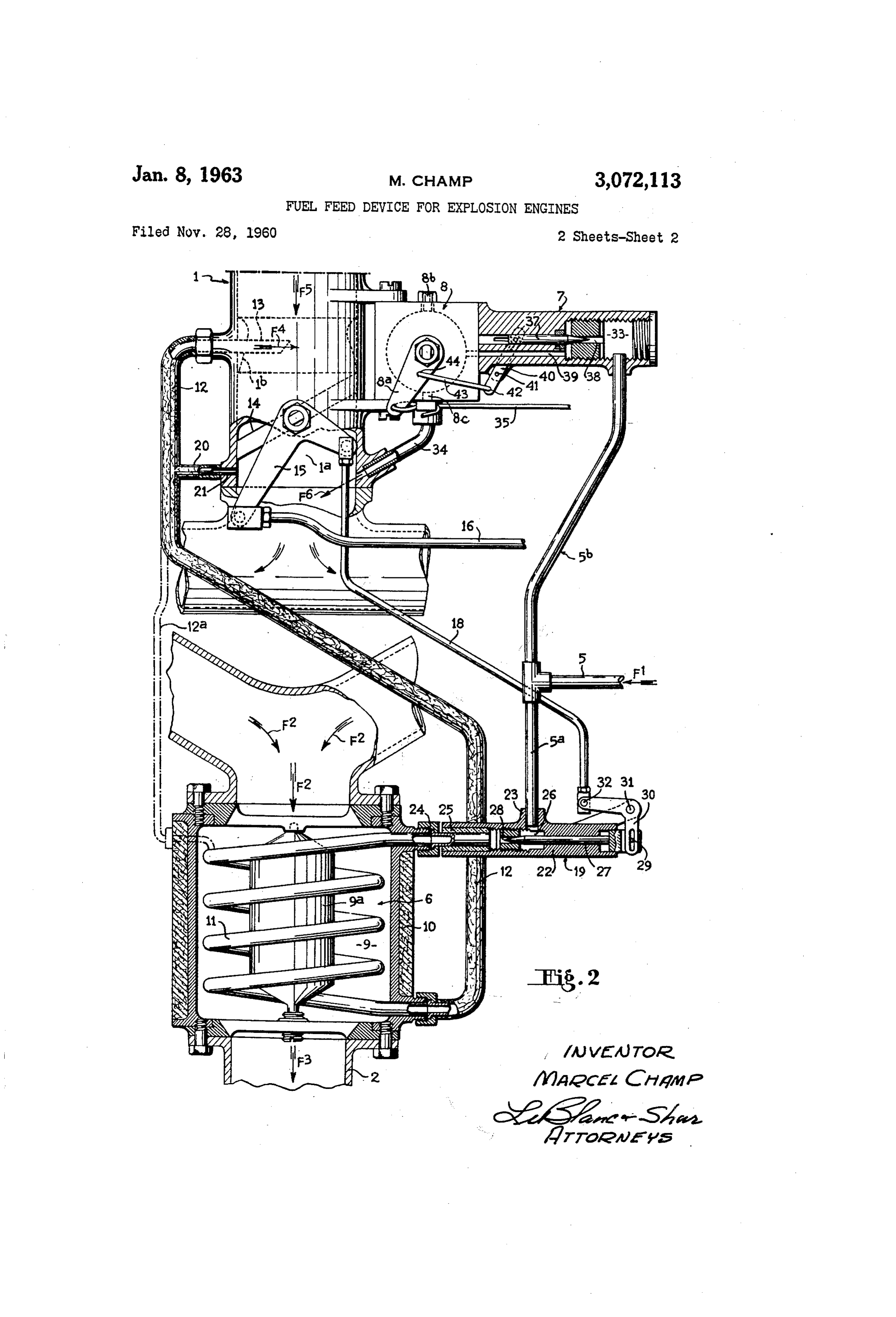
FUEL FEED DEWECE FOR EXPLOSGN ENGINES connected through a preferably-insulated conduit 2 with Marcel Champ, Route de Tinchebray, a tubular member 3 housed within the air-induction duct Wire, Calvados, France , and extending Substantially into the axis of the neck Filed Nov. 28, 1960, Ser. No. 72, a portion of the venturi 2b, b thereof upstream of the Caims priority, application France Jaa. 29, 1960 throttle disc 4. The latter is connected through a double i Claiga. (C. 123-133) lever 5, on the one hand, with a linkage 5 controllable In the U.S.A. patent S.N. 702,130 of December 11, by the accelerator pedal 17 (FIG. 1) and, on the other 1957, now Patent No. 2,895,462, granted July 21, 1959, IO hand, by a linkage i8 with a control means 59 for the there is disclosed an improved feed device for an explosion liquid-fuel input into the coil tube 1. engine allowing a considerable fuel economy, said device The conduit 12 includes a by-pass 23 provided with a comprising in particular a main feed device of the fuel tube 2: extending into the inlet circuit downstream of prevaporization type by the heat of the exhaust gas, for the throttle disc, this tube or nozzle 21 acting thus as an operation at normal running speeds of the engine. 5 idling jet which, as will be seen, is further fed from the An auxiliary device is used in this case for the starting main feed device 6.
and the idling speed of the engine and both feed devices The control means 9 of liquid-fuel admission into the are connected in parallel with a single feed manifold. An tube coil comprises a hollow body 22 connected, on the injection device enables the fuel to be injected into the one hand, at 23 on the fuel inter conduit 5a and, on the vaporization chamber of the main feed device by means 20 other hand, at 24 on the end of the tube coil. An insulat of a pump of the cylinder and piston type. ing sleeve 25 is interposed between the tube coil and the The object of the present application is to provide modi hollow body 22 to prevent heat convection therebetween. fications and improvements for this device, said modifi The fuel arrives into an inner recess 26 communicating cations and improvements aiming more particularly at with the inner duct of the tube coil 12, and said communi enabling the main feed device to be used when the engine 25 cation is regulated by a needle valve 27 controlling the is being run at idling speed, the auxiliary device being cross-sectional opening of a calibrated port 28, said needle only employed for the starting of the engine. In the valve being slidable in the block 22 and being connected known device, the auxiliary feed device is provided with at 29, by the end thereof exterior of this block, with a a carburetor of conventional design including a conven bell-crank lever 33 pivotable at 31 and pivotally con tional float chamber supplying in the usual fashion the 30 nected at 32 with the linkage 18.
normal jet and the idling jet and which also supplies a The branch line 5b of the conduit 5 extends into a well feeding in turn the vaporization chamber of the main chamber 33 of the auxiliary device 7, a conduit 30 estab device. lishing a communication between this chamber and the In the device designed in accordance with the present auxiliary self-starting carburetor 8. This self-starting invention, the auxiliary feed device merely comprises an 35 carburetor 8 may be of any known design and is adapted auxiliary self-starting carburetor of small capacity and of to provide communication between the chamber 33 with a generally known type currently used for the starting the inner space of the inlet conduit a downstream of of engines. The vaporization chamber of the main feed the throttle 14, Said communication being effected through device is comprised by a coil tube located inside a heat 40 a pipe 34 where the auxiliary self-starting carburetor is ing chamber, said coil tube being fed by a pulsating controlled through its arm 8a, which arm is connected diaphragm pump of conventional design, said coil tube in a known manner through a rod 35 to any type of ending by a tubular member extending into the engine air manual control member, such as a pull-button 36 suction pipe, upstream of the throttle disc. (FIG. 1).
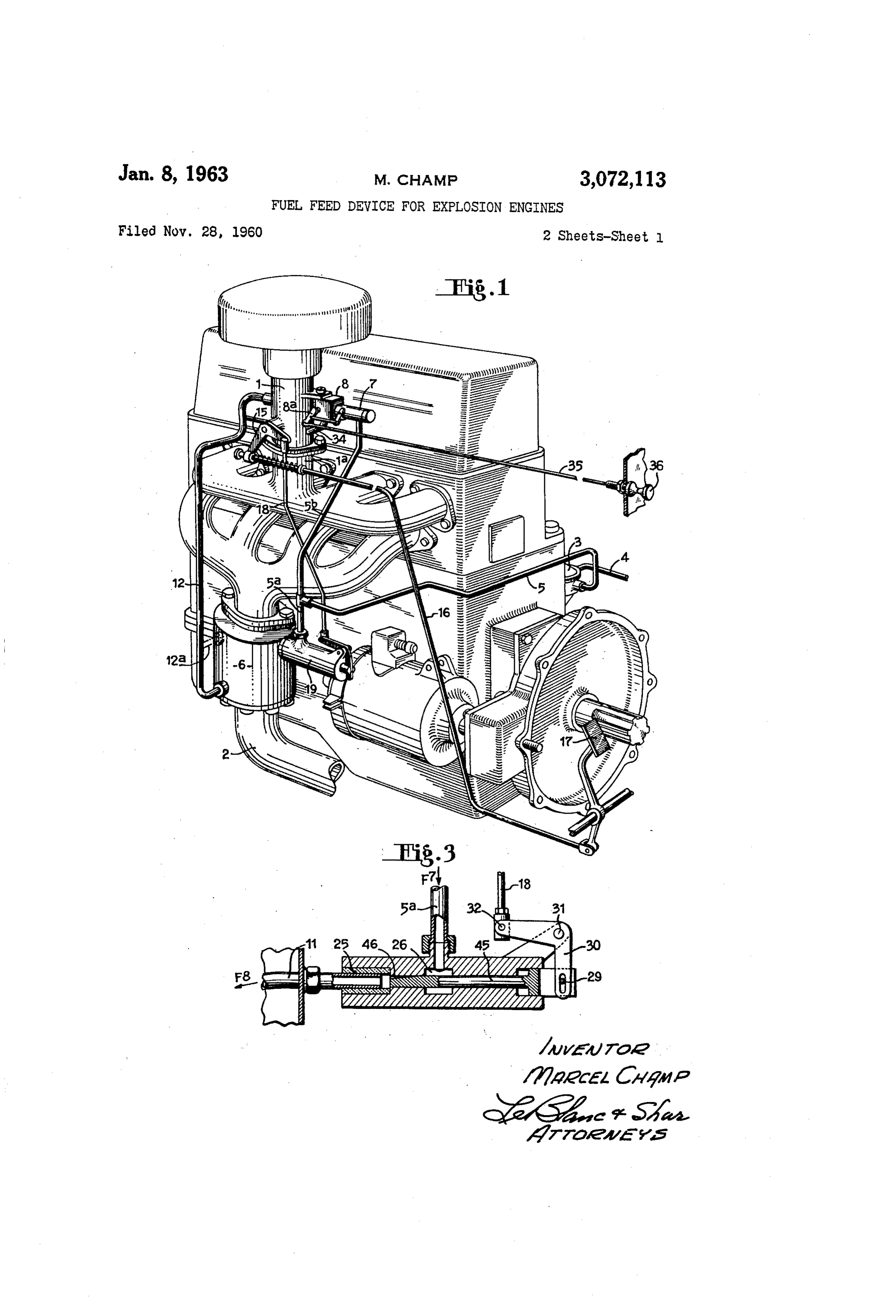
Further features of the invention will become apparent To this end, provision is made of a needle valve or from the ensuing description when read in connection with 45 any other plugging member 37 to control the opening or the accompanying drawings, in which: the closing of a calibrated orifice 33 which, through a FIG. 1 is a perspective view of an illustrative embodi conduit 39, establishes communication between the cham ment of an explosion engine provided with the improved ber 33 and the self-starting carburetor, which carburetor feed device, in accordance with the invention; upon being actuated, brings into direct communication FIG. 2 is a diagrammatic showing of this device; and 50 said conduit 39 with the conduit 34.
FIG. 3 is a sectional view of a detail showing an alter It will be obviously required that the opening of the native embodiment of one part of the invention. port 38 and the operation of the self-starting carburetor The illustrative embodiment shown in FIG. 1, the in take place simultanectisiy and, to this end, the needle vention is applied to an explosion engine of the four valve is pivotally connected with a lever 40 pivotable cylinder type, including a suction tube , an inlet conduit 55 at 4, and whose end 432 is articulated on a rod 43 which ia and a gas-exhaust manifold 2, said engine being fed is in turn pivotally mounted on the arm 8a of the car by a pulsating-diaphragm pump 3 of a known construc buretor 8.
tion and communicating through a pipe 4 with the fuel The improved device disclosed in the present addition tank (not shown). This pump discharges fuel under is operated as follows:
pressure into a line 5 which is subdivided in two branches 60 Under normal running conditions, the liquid fuel ar 5a and 5b adapted to feed the main feed device 6 and riving (FIG. 2) in the direction shown by the arrow FE the auxiliary starting device 7, respectively. The latter (FiG. 2) into the conduit 5, is fed through the branch device is mounted on the auxiliary self-starting carburetor 5a to the chamber 26 and, should the needie waive 27 be 8 which may be of any well-known device including an operated by means of the accelerator pedal, fuel pene outer lever 8a for controlling said auxiliary carburetor, 65 trates into the tube coil E., which coii is heated by corn and having an air inlet 8b and an air-fuel mixture outlet ing into the contact with hot gasses which flow through 8c. the exhaust duct in the direction of arrows F2 and F3. The main feed device 6 comprises a chamber 9 (FIG. This tube coil is further heated by the radiating heat 2) interposed on the hot-gas exhaust manifold 2, said from the wall of chamber 9 and fron the hollow body chamber being preferably heat-insulated by means of an 70 9a. This fuel which is by then yaporized, is induced by insulating wall 19. Within this chamber is located a coil the tube i (arrow F4) and flows into the duct a where tube 1 surrounding a hollow body member 9a secured it is mixed with air arriving in the direction F5, the inlet
Page 4
being regulated by the throttle E4, as known per se, by gradually increases the cross-sectional passage of the means of the rod 6 which is operated by the accelerator liquid fuel (arrow F7) towards the tube coil i (arrow pedal simultaneously with the rod 38, whereby the Supply F8).
into the coil tube and the gaseous fuel input to the it was found that with certain type of engines and tube 3 are always effected simultaneously. 5 for certain operating conditions thereof, a gas build-up With the engine idling and the throttle closed, the sole may take place in the tube coil i resulting in a phenom supply is effected through the idling jet 2i. it is shown enon similar to the well-known ram effect. Although by experience that the use of gaseous fuel for feeding this occurrence is not considered as a major drawback, he engine during slow-speed running offers the advan it can be prevented according to the invention, in an tage of eliminating the evolution of fumes and of tin alternative embodiment of which the upper portion of the pleasant and noxious smells which are inherent to con tube coil is connected with the air-induction conduit ventional internal combustion engines, when passing from through the tube 2a, shown in dash-dot in FIGS. 1 normal to idling speed. and 2.
it will be clear that the main feed device cannot be This tube 2a, as well as conduits 12 and 20, is prefer used for the self-siarting since the chamber 9 is at ambi 5 ably heat insulated.
ent temperature. The starting is effected by means of the It is to be understood that the invention is not re auxiliary device 7 which is fed under the pressure sup stricted to the embodiments thereof which have been plied by the diaphragm pump 3, which pressure is suf. shown and described merely by way of examples, and ficient for the fuel to be injected into the conduit 39 various modifications can be made therein without falling when the auxiliary self-starting carburetor S is operated, 20 outside the scope of the appended claim. whereupon the rotation of the arm 8a and hence of the Having now described my invention what I claim as lever 40 causes the needle valve 37 to open. The liquid new and desire to secure by Letters Patent is: fuel is injected through the auxiliary carburetor by the A running carburetor for running an explosion engine tube 34 into the injection conduit, as shown by the ar at normal speeds and idling speed, said running car row F5. 25 buretor comprising: a vaporization chamber adapted to After the engine has been running for some time and be so mounted on the engine as to be traversed by the the chamber 9 has been brought to a sufficient tempera flow of the exhaust gases of said engine, a coii tube in ture for the fuel vaporization to take place normally in said chamber, a fixed heat-radiating body surrounded by the tube coil i, the arm 8a may be returned to its nor the coils of said coil tube in said vaporization chamber, mal operative position and the engine is running under 30 and tube connecting means for connecting said coil tube normal conditions being fed from the device 6. to a fuel feed conduit and to a vapor feed conduit. In the control device 9, the flow-rate control member which is embodied in FIG. 2 by the needle valve 27, References Citesi in the file of this patent can be of a different type, such as for example a spool UNITED STATES PATENTS with a variable section port. In FIG. 3 is shown a 35
Specific alternative embodiment wherein the control hem 1,060,042 Wales ----------------- Apr. 29, 1913 ber is comprised by a spool 45 consisting of a rod hay 1,377,529 Trotter --------------- May 10, 1921 ing a groove 46 formed therein, whose cross-section is 1,728,323 Bartley ----------- -- Sept. 17, 1929 increasing such that a rightwardly shift of the rod 45 2,895,462 Champ --------------- July 21, 1959
Provenance
- Collection
- Cited prior art
- Original PDF
- patentimages.storage.googleapis.com →
- Filed
- 1960-11-28
- Pages
- 4
- Method
- pdftotext (the PDF's own text layer) + pdftoppm 300dpi page scans
- Source
- Google Patents bibliographic record
- Granted
- 1963-01-08
- Inventors
- Champ Marcel
- Transcribed from
- patentimages.storage.googleapis.com →