patent · US3630698
Fuel system
28 December 1971
Page 1 — bibliographic record
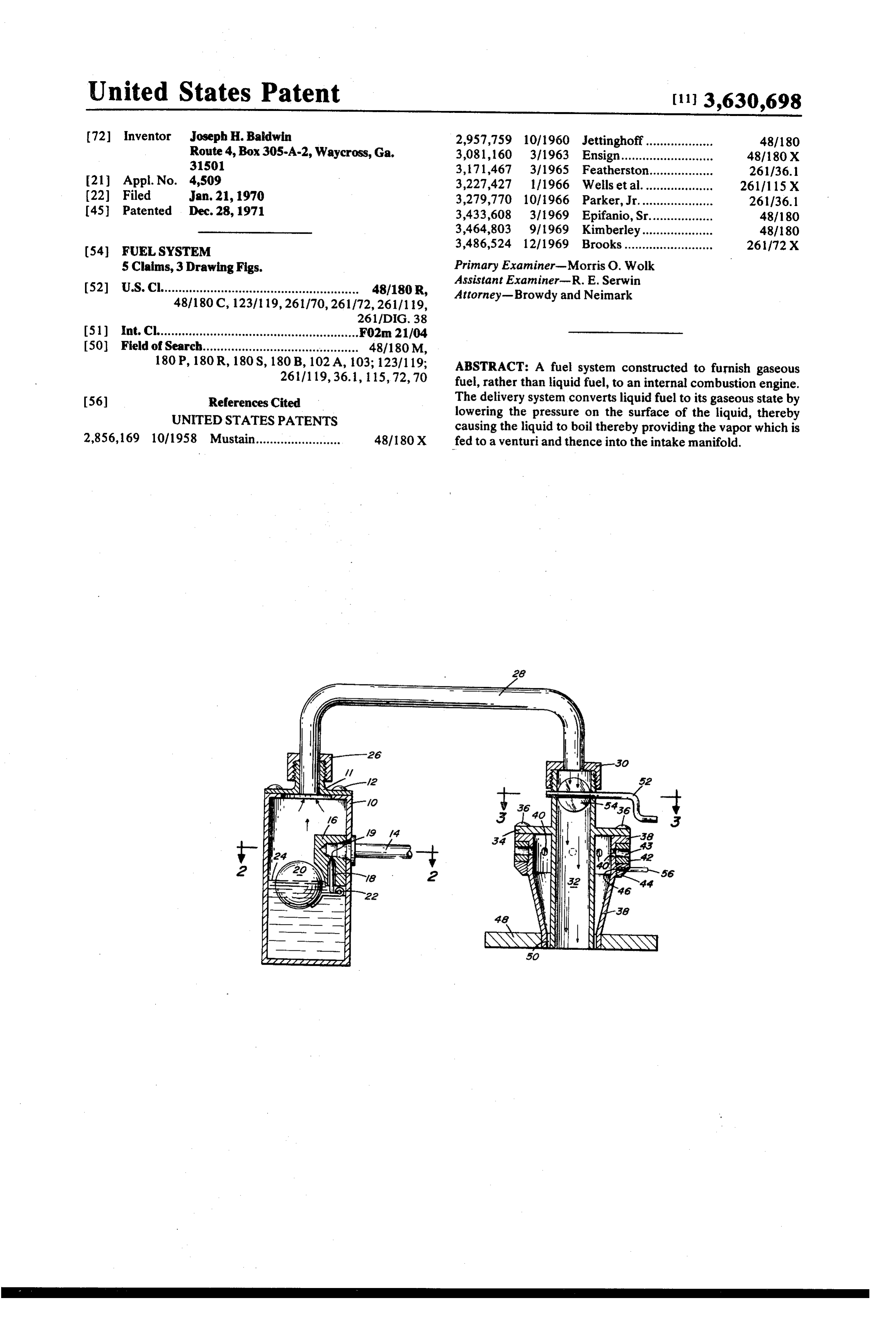
United States Patent [11] 3,630,698 (72) Inventor Joseph H. Baldwin 2,957,759 10/1960 Jettinghoff................... 48/180 Route 4, Box305-A-2, Waycross, Ga. 3,081,160 3/1963 Ensign............ - 48/180 X 31501 3, 171467 3/1965 Featherston.... 261/36.1 21 Appl. No. 4,509 3,227,427 1/1966 Wells et al.. 26111 15 X (22 Filed Jan. 21, 1970 3,279,770 10/1966 Parker, Jr..................... 261136.1 45 Patented Dec. 28, 1971 3,433,608 3/1969 Epifanio, Sr.................. 48/180 3,464,803 9/1969 Kimberley. 48/180 (54) FUEL SYSTEM 3,486,524 12/1969 Brooks......................... 261/72X 5 Claims, 3Drawing Figs. Primary Examiner-Morris O. Wolk
Assistant Examiner-R. E. Serwin (52) U.S. Cl........................................................ 48/180R, Attorney-Browdy and Neimark
I51) int. Cl......................................................... F02m 21/04 (50 Field of Search............................................ 48/180M, 180 P, 180 R, 180S, 180 B, 102A, 103; 12311 19; ABSTRACT: A fuel system constructed to furnish gaseous 2611119, 36.1, 115,72, 70 fuel, rather than liquid fuel, to an internal combustion engine.
56) References Cited The delivery system converts liquid fuel to its gaseous state by UNITED STATES PATENTS lowering the pressure on the surface of the liquid, thereby causing the liquid to boil thereby providing the vapor which is 2,856,169 10/1958 Mustain........................ 48/180 X fed to a venturi and thence into the intake manifold.
Page 2
Drawing sheet — no readable text.
Page 3
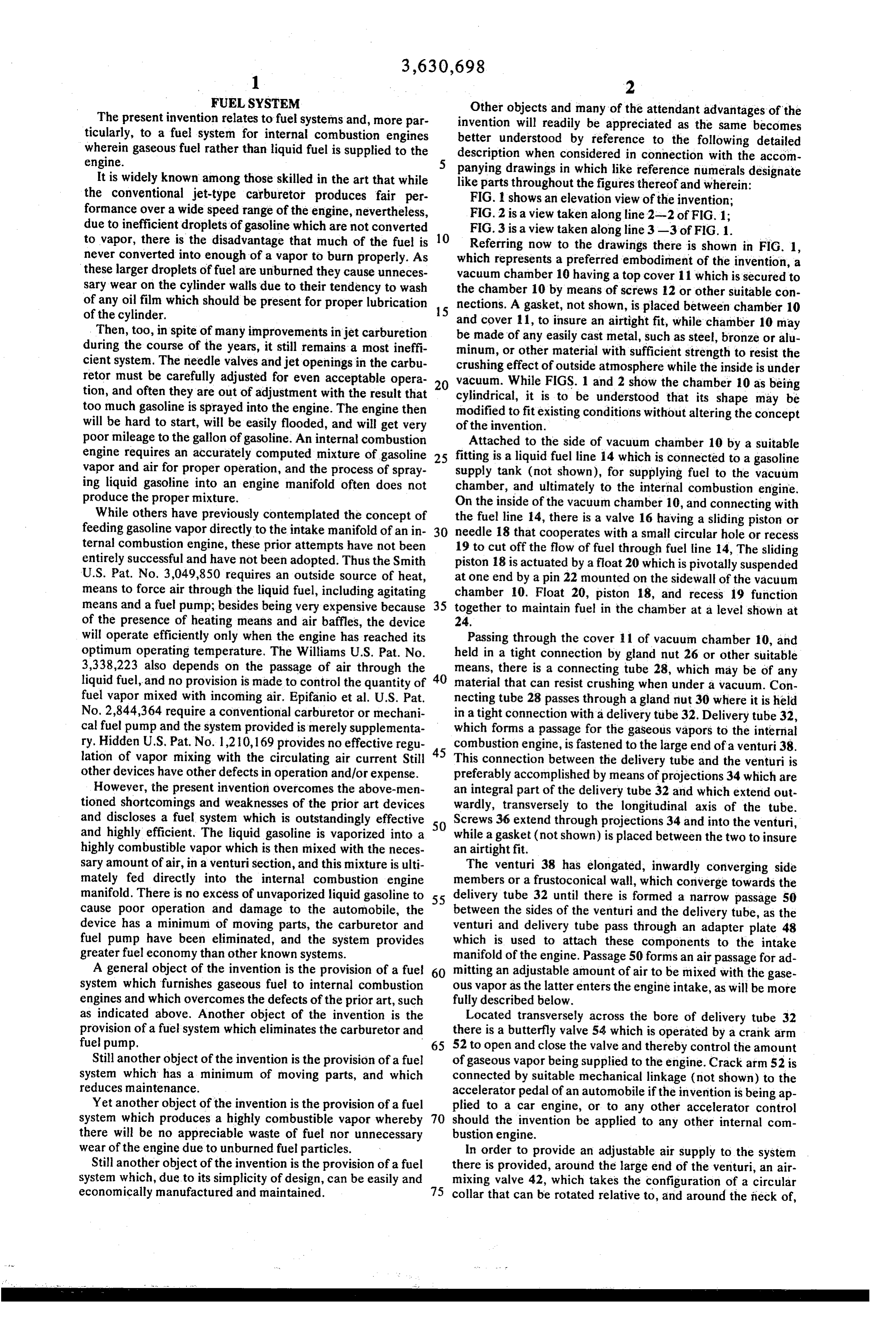
FUEL SYSTEM Other objects and many of the attendant advantages of the The present invention relates to fuel systems and, more par invention will readily be appreciated as the same becomes ticularly, to a fuel system for internal combustion engines better understood by reference to the following detailed wherein gaseous fuel rather than liquid fuel is supplied to the description when considered in connection with the accom engine.
It is widely known among those skilled in the art that while panying drawings in which like reference numerals designate like parts throughout the figures thereof and wherein:
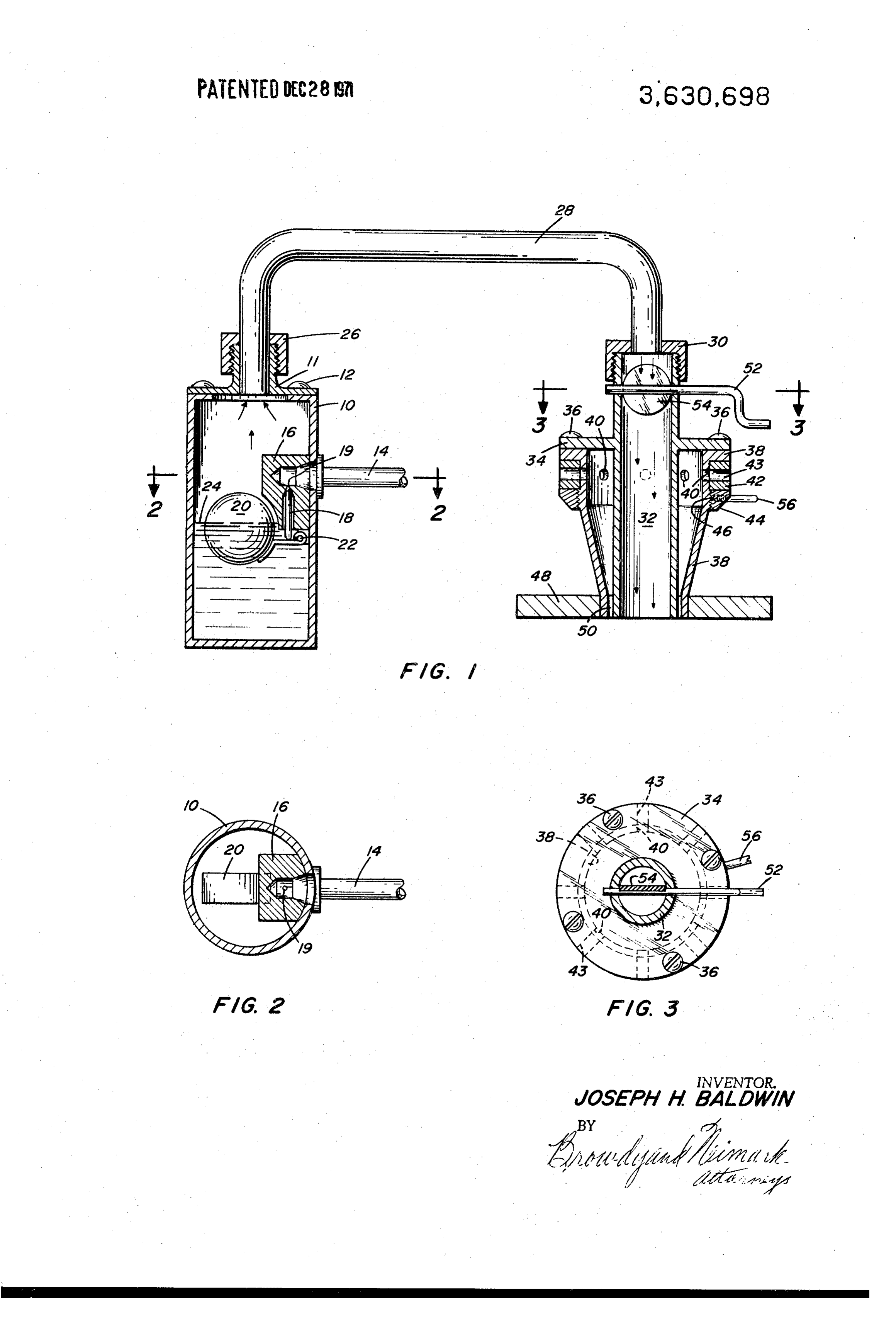
the conventional jet-type carburetor produces fair per FIG. 1 shows an elevation view of the invention; formance over a wide speed range of the engine, nevertheless, FIG. 2 is a view taken along line 2-2 of FIG.1; due to inefficient droplets of gasoline which are not converted FIG. 3 is a view taken along line 3-3 of FIG. 1. to vapor, there is the disadvantage that much of the fuel is 10
Referring now to the drawings there is shown in FIG. 1, never converted into enough of a vapor to burn properly. As which represents a preferred embodiment of the invention, a these larger droplets of fuel are unburned they cause unneces vacuum chamber 10 having a top cover 11 which is secured to sary wear on the cylinder walls due to their tendency to wash the chamber 10 by means of screws 12 or other suitable con of any oil film which should be present for proper lubrication 15 nections. A gasket, not shown, is placed between chamber 10 of the cylinder. and cover 11, to insure an airtight fit, while chamber 10 may Then, too, in spite of many improvements injet carburetion during the course of the years, it still remains a most ineffi be made of any easily cast metal, such as steel, bronze or alu cient system. The needle valves and jet openings in the carbu crushingoreffect minum, other material with sufficient strength to resist the of outside atmosphere while the inside is under retor must be carefully adjusted for even acceptable opera 20 vacuum. While FIGS. 1 and 2 show the chamber 10 as being tion, and often they are out of adjustment with the result that too much gasoline is sprayed into the engine. The engine then cylindrical, it is to be understood that its shape may be modified to fit existing conditions without altering the concept will be hard to start, will be easily flooded, and will get very of the invention.
poor mileage to the gallon of gasoline. An internal combustion Attached to the side of vacuum chamber 10 by a suitable engine requires an accurately computed mixture of gasoline 25 fitting is a liquid fuel line 14 which is connected to a gasoline vapor and air for proper operation, and the process of spray supply tank (not shown), for supplying fuel to the vacuum ing liquid gasoline into an engine manifold often does not chamber, and ultimately to the internal combustion engine. produce the proper mixture. On the inside of the vacuum chamber 10, and connecting with While others have previously contemplated the concept of the fuel line 14, there is a valve 16 having a sliding piston or feeding gasoline vapor directly to the intake manifold of an in 30 needle 18 that cooperates with a small circular hole or recess ternal combustion engine, these prior attempts have not been 19 to cut off the flow of fuel through fuel line 14, The sliding entirely successful and have not been adopted. Thus the Smith piston 18 is actuated by a float 20 which is pivotally suspended U.S. Pat. No. 3,049,850 requires an outside source of heat, at one end by a pin 22 mounted on the sidewall of the vacuum means to force air through the liquid fuel, including agitating chamber 10. Float 20, piston 18, and recess 19 function means and a fuel pump; besides being very expensive because 35 together to maintain fuel in the chamber at a level shown at of the presence of heating means and air baffles, the device 24.
will operate efficiently only when the engine has reached its Passing through the cover 1 of vacuum chamber 10, and optimum operating temperature. The Williams U.S. Pat. No. held in a tight connection by gland nut 26 or other suitable 3,338,223 also depends on the passage of air through the means, there is a connecting tube 28, which may be of any liquid fuel, and no provision is made to control the quantity of 40 material that can resist crushing when under a vacuum. Con fuel vapor mixed with incoming air. Epifanio et al. U.S. Pat. necting tube 28 passes through a gland nut 30 where it is held No. 2,844,364 require a conventional carburetor or mechani in a tight connection with a delivery tube 32. Delivery tube 32, cal fuel pump and the system provided is merely supplementa which forms a passage for the gaseous vapors to the internal ry. Hidden U.S. Pat. No. 1,210,169 provides no effective regu 45 combustion engine, is fastened to the large end of a venturi 38. lation of vapor mixing with the circulating air current Still This connection between the delivery tube and the venturi is other devices have other defects in operation and/or expense. preferably accomplished by means of projections 34 which are However, the present invention overcomes the above-men an integral part of the delivery tube 32 and which extend out tioned shortcomings and weaknesses of the prior art devices wardly, transversely to the longitudinal axis of the tube. and discloses a fuel system which is outstandingly effective Screws 36 extend through projections 34 and into the venturi, and highly efficient. The liquid gasoline is vaporized into a 50 while a gasket (not shown) is placed between the two to insure highly combustible vapor which is then mixed with the neces an airtight fit.
sary amount of air, in a venturisection, and this mixture is ulti The venturi 38 has elongated, inwardly converging side mately fed directly into the internal combustion engine members or a frustoconical wall, which converge towards the manifold. There is no excess of unvaporized liquid gasoline to 55 delivery tube 32 until there is formed a narrow passage 50 cause poor operation and damage to the automobile, the between the sides of the venturi and the delivery tube, as the device has a minimum of moving parts, the carburetor and venturi and delivery tube pass through an adapter plate 48 fuel pump have been eliminated, and the system provides which is used to attach these components to the intake greater fuel economy than other known systems. manifold of the engine. Passage 50 forms an air passage for ad A general object of the invention is the provision of a fuel 60 mitting an adjustable amount of air to be mixed with the gase system which furnishes gaseous fuel to internal combustion ous vapor as the latter enters the engine intake, as will be more engines and which overcomes the defects of the prior art, such fully described below.
as indicated above. Another object of the invention is the Located transversely across the bore of delivery tube 32 provision of a fuel system which eliminates the carburetor and there is a butterfly valve 54 which is operated by a crank arm fuel pump. 65 52 to open and close the valve and thereby control the amount Still another object of the invention is the provision of a fuel of gaseous vapor being supplied to the engine. Crack arm 52 is system which has a minimum of moving parts, and which connected by suitable mechanical linkage (not shown) to the reduces maintenance. accelerator pedal of an automobile if the invention is being ap Yet another object of the invention is the provision of a fuel plied to a car engine, or to any other accelerator control system which produces a highly combustible vapor whereby 70 should the invention be applied to any other internal com there will be no appreciable waste of fuel nor unnecessary bustion engine.
wear of the engine due to unburned fuel particles. In order to provide an adjustable air supply to the system Still another object of the invention is the provision of a fuel there is provided, around the large end of the venturi, an air system which, due to its simplicity of design, can be easily and mixing valve 42, which takes the configuration of a circular economically manufactured and maintained. 75 collar that can be rotated relative to, and around the neck of,
Page 4
the venturi. There are provided a plurality of spaced holes 40 heating coil, or hot air could be directed around the bottom of drilled around the periphery of the venturi walls, and a like the vacuum chamber.
number of holes 43 drilled in the air-mixing valve 42. Rota As the engine operates, the fuel level inside the vacuum tional adjustment of valve 42 so that holes 40 and 43 line up, chamber is lowered due to the boiling of the liquid. In order to or become misaligned, determines the amount of air being ad maintain the liquid level 24, a float 20 and valve 16 arrange mitted by the venturi for mixing with the gaseous vapor. Valve ment is installed in the vacuum chamber 10, and as the fiel 42 is connected to the engine accelerator by mechanical level lowers, float 20 pivots about its mounting pin 22 causing means (not shown) so that the volume of air being admitted piston 18 to move downwardly and uncover opening 19 in fuel into the engine is constantly varied depending on the speed of supply line 14, connecting with a conventional fuel tank. As the engine. In its closed position the valve acts as a choke by O piston 18 uncovers opening 19 fuel is forced into the vacuum shutting off all of the air supply. chamber by the atmospheric pressure exerted on the surface Below the valve 42, and also encircling the neck of the ven of the liquid fuel in the main tank. As the level of the fuel rises, turi, there is an adjusting collar 44. Collar 44 and the venturi float 20 rotates clockwise about its pivot 22 forcing piston 18 body have matching threads 46 for the correct positioning of upward to close off opening 19 in the fuel line. Since the fuel is valve 42, and a setscrew 56 is provided for locking collar 44 in 15 consumed running.
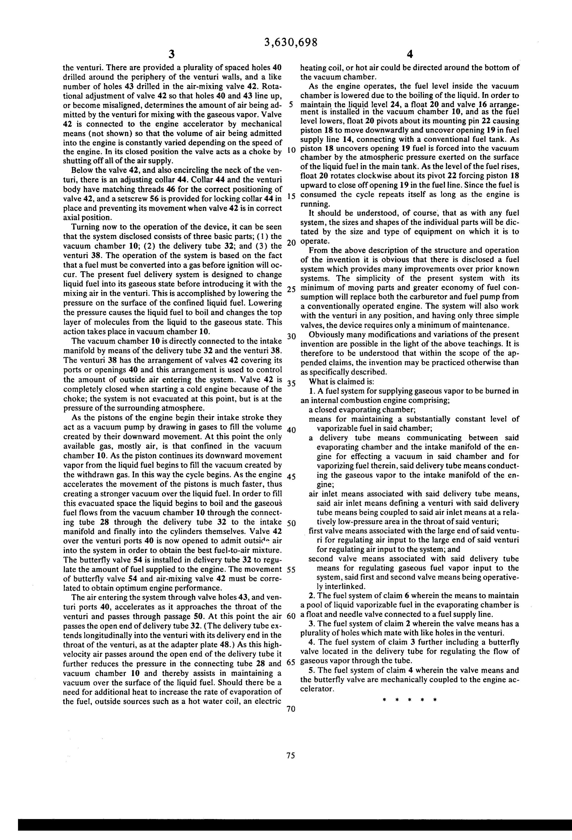
the cycle repeats itself as long as the engine is place and preventing its movement when valve 42 is in correct It should be understood, of course, that as with any fuel axial position. system, the sizes and shapes of the individual parts will be dic Turning now to the operation of the device, it can be seen tated by the size and type of equipment on which it is to that the system disclosed consists of three basic parts; (1) the 20 operate.
vacuum chamber 10; (2) the delivery tube 32; and (3) the From the above description of the structure and operation venturi 38. The operation of the system is based on the fact of the invention it is obvious that there is disclosed a fuel that a fuel must be converted into a gas before ignition will oc system which provides many improvements over prior known cur. The present fuel delivery system is designed to change systems. The simplicity of the present system with its liquid fuel into its gaseous state before introducing it with the 25 minimum of moving parts and greater economy of fuel con mixing air in the venturi. This is accomplished by lowering the sumption will replace both the carburetor and fuel pump from pressure on the surface of the confined liquid fuel. Lowering a conventionally operated engine. The system will also work the pressure causes the liquid fuel to boil and changes the top with the venturi in any position, and having only three simple layer of molecules from the liquid to the gaseous state. This valves, the device requires only a minimum of maintenance. action takes place in vacuum chamber 10. 30 Obviously many modifications and variations of the present The vacuum chamber 10 is directly connected to the intake invention are possible in the light of the above teachings. It is manifold by means of the delivery tube 32 and the venturi 38. therefore to be understood that within the scope of the ap The venturi 38 has the arrangement of valves 42 covering its pended claims, the invention may be practiced otherwise than ports or openings 40 and this arrangement is used to control as specifically described.
the amount of outside air entering the system. Valve 42 is 35 What is claimed is:
completely closed when starting a cold engine because of the 1. A fuel system for supplying gaseous vapor to be burned in choke; the system is not evacuated at this point, but is at the an internal combustion engine comprising; pressure of the surrounding atmosphere. a closed evaporating chamber;
As the pistons of the engine begin their intake stroke they means for maintaining a substantially constant level of act as a vacuum pump by drawing in gases to fill the volume 40 vaporizable fuel in said chamber; created by their downward movement. At this point the only a delivery tube means communicating between said available gas, mostly air, is that confined in the vacuum evaporating chamber and the intake manifold of the en chamber 10. As the piston continues its downward movement gine for effecting a vacuum in said chamber and for vapor from the liquid fuel begins to fill the vacuum created by vaporizing fuel therein, said delivery tube means conduct the withdrawn gas. In this way the cycle begins. As the engine 45 ing the gaseous vapor to the intake manifold of the en accelerates the movement of the pistons is much faster, thus gine, creating a stronger vacuum over the liquid fuel. In order to fill air inlet means associated with said delivery tube means, this evacuated space the liquid begins to boil and the gaseous said air inlet means defining a venturi with said delivery fuel flows from the vacuum chamber 10 through the connect tube means being coupled to said air inlet means at a rela ing tube 28 through the delivery tube 32 to the intake 50 tively low-pressure area in the throat of said venturi; manifold and finally into the cylinders themselves. Valve 42 first valve means associated with the large end of said ventu over the venturi ports 40 is now opened to admit outside air ri for regulating air input to the large end of said venturi into the system in order to obtain the best fuel-to-air mixture. for regulating air input to the system; and The butterfly valve 54 is installed in delivery tube 32 to regu second valve means associated with said delivery tube late the amount of fuel supplied to the engine. The movement 55 means for regulating gaseous fuel vapor input to the of butterfly valve 54 and air-mixing valve 42 must be corre system, said first and second valve means being operative lated to obtain optimum engine performance. ly interlinked.
The air entering the system through valve holes 43, and ven 2. The fuel system of claim 6 wherein the means to maintain turi ports 40, accelerates as it approaches the throat of the a pool of liquid vaporizable fuel in the evaporating chamber is venturi and passes through passage 50. At this point the air 60 a float and needle valve connected to a fuel supply line. passes the open end of delivery tube 32. (The delivery tube ex 3. The fuel system of claim 2 wherein the valve means has a tends longitudinally into the venturi with its delivery end in the plurality of holes which mate with like holes in the venturi. throat of the venturi, as at the adapter plate 48.) As this high 4. The fuel system of claim 3 further including a butterfly valve located in the delivery tube for regulating the flow of velocity air passes around the open end of the delivery tube it gaseous further reduces the pressure in the connecting tube 28 and 65 vapor through the tube. vacuum chamber 10 and thereby assists in maintaining a 5. The fuel system of claim 4 wherein the valve means and vacuum over the surface of the liquid fuel. Should there be a the butterfly valve are mechanically coupled to the engine ac need for additional heat to increase the rate of evaporation of celerator.
the fuel, outside sources such as a hot water coil, an electric
Provenance
- Collection
- Cited prior art
- Original PDF
- patentimages.storage.googleapis.com →
- Filed
- 1970-01-21
- Pages
- 4
- Method
- pdftotext (the PDF's own text layer) + pdftoppm 300dpi page scans
- Source
- Google Patents bibliographic record
- Granted
- 1971-12-28
- Inventors
- Joseph H Baldwin; JOSEPH H BALDWIN
- Transcribed from
- patentimages.storage.googleapis.com →