patent · US3447511
Fuel generator
3 June 1969
Page 1
Drawing sheet — no readable text.
Page 2
Drawing sheet — no readable text.
Page 3
Drawing sheet — no readable text.
Page 4
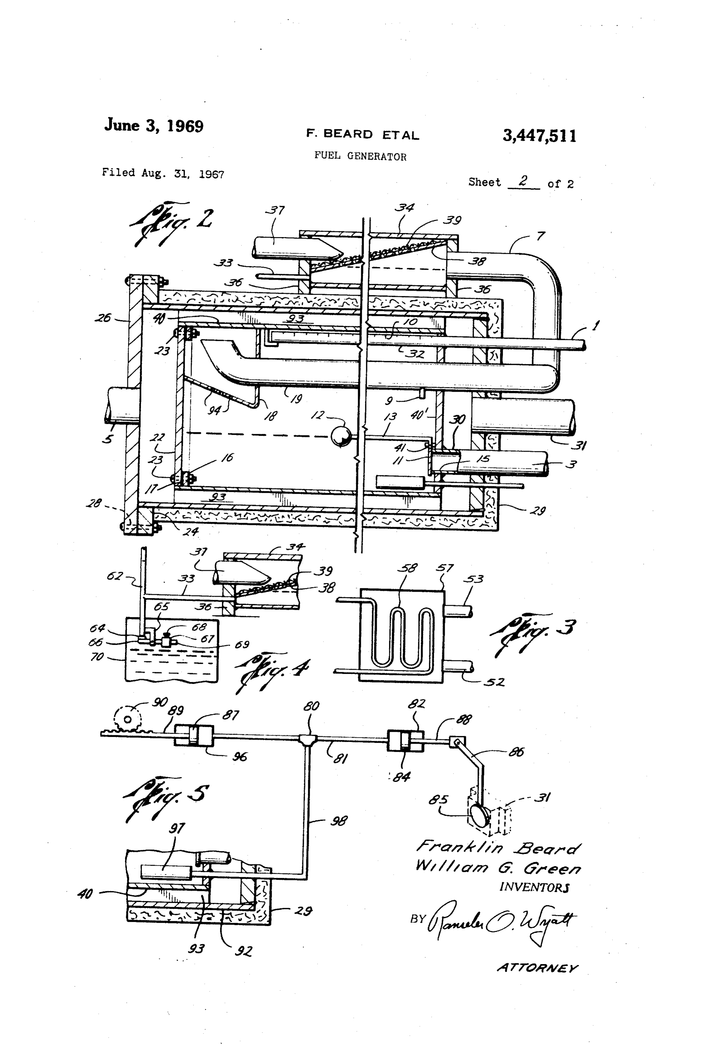
(b)Furtherheatingthe oiinasecond heatexchanger weldedon theinside walthereofatthe oppositeend to to a temperature suficientto extract ten percent of thewhich the end plate22is detachablymountedasby bolts treatedoilasgas? 23,23andagasket17ismounted between thering16 (c)Maintaininga positive pressure onthe fuid whie andtheendplate22.Theinnercylinder40isspacedfrom itisbeing heated,to preventescape ofthegas,andmain theinsidewallsofthe outercylinder92bymeans ofthe tainingaliquid vaporseal,controlled topermitthe con fiutes 93,An enclosure 18ismountedatone end of the tinuousinfuxoffreshoiataratewhichwilpermittak inner cylinder 40,preferably by welding same to the ingten percent of the oil,no more,and noless? upperinsidewalthereofandthe bottom ofsaidenclosure (d)Pumpingthe oilwith a controled volume pump forming upwardy inclined bafes,provided with drain toinsurethatthe properamountofoilispassedthrough openings94,94?
thetreatingunit. - Afoat valve consisting of the foat12,foatarm13, (e)Collecting the residue oiland pumpingit back pivot41 and closure 11 which seatsagainst the Tefon into the line tostorage,wherebyitis mixed bythe tur seat15on the discharge conduit3?extended through the bulence ofthepumpandpassagethroughtheline? end plates39,40”into the inner vessel40,maintainsa (f)Passingthe gas through the Screensinto a Space predetermined1evelofoilinthe vesse140. where the volume is suficient that the fow rate wil Adischarge conduit19ismountedintheinnervessel diminish to a low value to permitthe condensation and 40,andhasan open end upwardlyinclined and paralel Drecipitation of the lower fractions thereof,as wellas with the upper wal of the innervessel,and in close actualdropletsof distillate,and proximitytosaidupperwal.Thisconduitextendsthrough g)Passingthe gasinto a Second dryingarea,where 20 theend plates40’and29and dischargesintothesecond thetemperatureissubstantiallybelow500°F.to further dryer34and comprisesthe flowline 7.The second dryer condense such fractionsas wildrop out,thus leavinga 34is mounted on the top of the outervesse192,as by gas Stabje enough to passinto a gas carburetor of the means of the Supports 36,36,welded to the outersur engine? face ofthe vesse192.Adrain9ismountedintheconduit (h)Collecting the condensate in the Second drying 19,extendingthroughthe bottom wal,toprovide means chamberandstoringitforusein vehicles,andinstarting for discharging condensate?A perforated bafe 38 is the operation,asagas-oiburner ofthe blow-torchtype, mountedin the dryer34andascreen 39ismounted on aswilbe described, thesaid bafe38.The bafie38andscreen39aremounted Alloftheforegoingforthe purpose of providingagaS atanangle toprovide drainage bygravity ofanymist equivalenttonaturalgas ofthe quality necessaryfor op 30 remainingin thegas passingtherethrough,andwhichas eratingagasengine;orfordistilatesofthe qualitysatis Condensatewilpassthroughthe conduit33,whichisin factory for gasolene or diesel engines,from the waste fow connection with the discharge conduit 62.A con heatofthe primary engine,withoutthe waste ofany of duit37 extends through the discharge end ofthe dryer the fuel,andinsofaras possible,withoutloss of price of 34andisinfow connection with the carburetorintake6 the crude oil So treated and evapOrated? wheretheintakeiscontrolled bythe usualregulator(not shown).
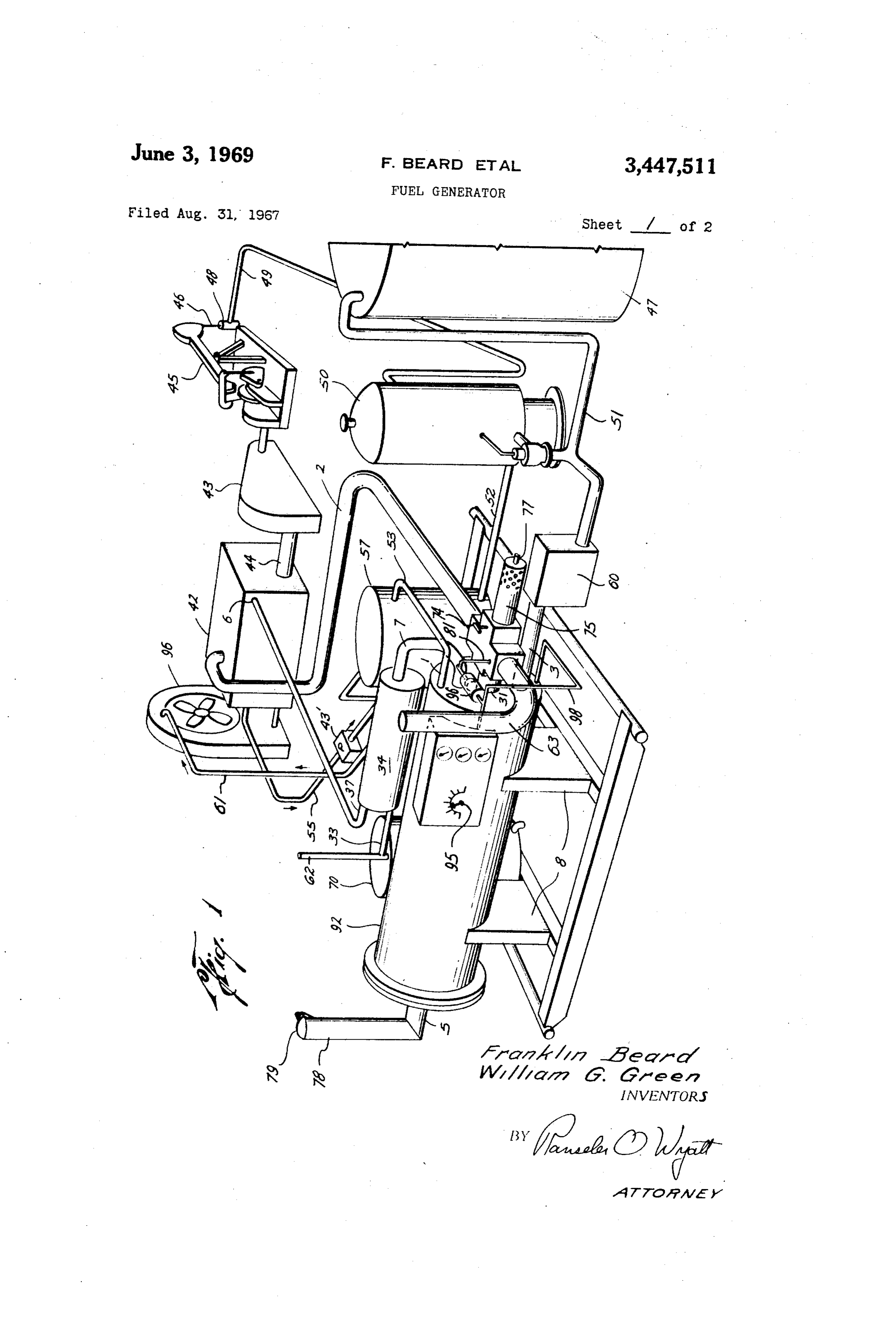
Briefdescription of the dravings Adistilate tank70isprovidedinto whichthe conduit FIGURE1 isa perspective elevational view of the 33 discharges?Aliquid-gas pressuresea162is provided generatorattached to a motorandoperatinga pump? betweenthe dischargeend of the conduit33andthe dis FIGURE 2isan elevationalview,partialy in cross 40 tilatetank70.Adump valve comprisingthedump valve Section,ofthe distilatetankand control? Support65,Seal64andsealsupport66andthe1evelarm FIGURE3isafragmentaryview ofthe heatexchange 69 on which the adjustable weight67ismounted,said meansemployed? weightbeinganchoredina predetermined position byset FIGURE4isa fragmentary elevationalview of the Screw 68. - distiatestorage control? The pump onthe welisactivated bythe engine42 FIGURE5isanelevationalview,partiallyincrosssec which has the usual radiator 96,exhaustmanifoldand tion,ilustrating the temperature by-pass control? carburetor,A drive shaft44 powersthe pump in the Description of the preferredenbodiment usualmannerand connectedtheretoisthe usualmecha In the drawings,a pump having the usual counter nism which inturn operatesa pump(notshown)to balancedjack45,operatingonabearing,pumpSpetroleum 50 pumpthe condensatefrom the heatexchanger57through from the wel48,and hasthe usual polish rod46and the fowline 61 backinto the engine coolingsystem?A Productionfowline49whichleadsintothe separator50 thermostatin the engine diverts steaminto the ine 55 for conveyanceintothe heatexchanger.Hotexhaustgases of a conventionaltype,or simiartype of storage unit which wilmaintainan oillevelatleastthree feetabove from the engine manifold pass through the fow line2 the top of the dryer vessel hereinafter referred to?A 55 into the outer vessel92andis exhausted through the fowline 5intothestack78.Arain seal79is mounted conduit,as51,1eadsfrom the separatortoatankorpipe lineas47wherea backPreSSure,or head,isencountered? onthetop ofthestack78.
The fow line2 wilbeinsulated to prevent heat1oss,
A conduit521eads from the Separator50into the heat exchanger57and directsa Supply of petroleum through and gaSes therefrom pass through the bypassassembly the preheating cois 58,and the conduit53,containing 60 Shown in FIGURE 5,consisting of the T80 andthe preheated petroleum,Ieads from the heatexchanger57 conduit81 infow connectionwith the conduit31form to the conduit1 whichisin fow connection with the ing fow line 2.The line 81 connectedinto the T80 distributortube 32 andthe tube 32is provided with a hasthe butterfyvalve 85andoperatinglever86pivoted Series of slots 19,10 for the distribution of the oil at 92tothe piston rod84whichisconnectedtothe pis againstthewalls of theinnerdistilation vessel40which 65 ton88 mountedinthe cylinder82.Thepiston 87ispro is preferably cylindricalin formandismountedin the vided with a rack89 which hasan operatinggear90 outer vessel92,whichis also preferably cyindricalin - controled by a knob 95 on the outside ofthetank92. form andis Supportedin any Suitable manneras bythe A cylinder 97is mountedin theinnertank40andisin Supports8,8andwhichissealedbytheendplates26,29? fow connection with the T80 bymeans ofthe ine98. the plate29 beingwelded to oneend ofthe cyinder 92 70 This cylinderis fled with an expandible fuid,Heat anda steelring24is mountedatthe otherend of the changesinthe exhaustchamberadjacenttothefowine cylinder 92and bolt holes28are provided through the 2Wilrefect theamount of heatabsorbedinthe distia end plate26andring24to detachablymountthesaid tion proceSS?If the distillate becomestoo hot,the fuid end plate26on the cytinder.Theinnercyinder40has inside the cylinder 97wil expandand bearagainstthe anendplate 40”weldedin oneendandasteelring1675piston84andopenthevalve85,thuspermittinghotgas
Page 5
to be bypassedandexhausted throughthe stack 63 unti iished,it wilbefoundthatsteamat240°F.isavailable the heatin the vessel92 decreasesand closes the Valve atslighty over12 psig;aconnectionprovidedbetween 85.The knob 95may beadjusted to turn the gear 90 andadjust the position ofthe piston 87,which wide
terminethe pointatwhich the valve 85wilbe opened.
throughthe ppe 55,tothe space in the heatexchanger
The starter employed for starting the generating of ingthe oitoapproximatey240°F.Inthe coolingofthe gasissimilarto a blow-torch(notshown)mountedin Steam,ingivingupits heattothe oil,condensationtakes the housing 75,and which usesa startingfuel Such as Place,and,ifthe heatexchangerishigherthanthecon gasoline or distilate from the tank 70fed through the nection throughthe Said pipe 61totheradiator,there ine 77?This heats the petroleum in the tank 40 and 10 wilbegravitydrainage ofthe condensatetotheradiator? Starts the gasgeneration?Amanualy operable valve 74 AValveinline52(notshown)metersthe oilfrom opens the fow line2 to the exhaust gas of the engine the Separator50intothe heatexchanger57,andthence to start the flowintothe yessel92.The vein valve 79on intotheoi distributorine1 and distributortube32in the exhaustStackmust be propped open duringthe start the distilation unit,as shown in FIGURE2.Theoi1is ingprocesstopreventbackpressure? ?orced outthroughthe slots10,10impinginguponthe Operation of the generator inside Surface ofthe distilationvessel40whichissealed bythe weight of the foat12andarm13against the
Evaporation takes place with almostall liquids,and Seal11,closingthe pipe30inthefowline3untithe the evaporation rate increasesasthe temperature of the o??sestothe levelline shown.Abovethisine,excess liquid approachesthe boilingpoint?Forwater,the tem 20 oilliftsthefoatand opensthe sealedvalve11andre perature cannotincrease beyondthe boing pointatany leases Some oi,Since oilis continuously enteringthe given pressure,but mayincrease with pressure?For cer Vesselthroughtheslots,10,10,there wi1beoi11eaving tain compleXliquids,Such as petroleum,the temperature continuousythroughtheppe30,inthesame quantity, frst stabilizesatthe boilingpoint ofthe lightestormost lessthe fuidsthathave been distiled off.Thisexcessis volatie elements?and when these have been evaporated, 25 delivered where desired,such asinto the line51tothe it may progress to the next highestfraction?Thus,al Storagetank47.
though the boiling point of certain crude ois may be ?ot?exhaust gases from the exhaust manifold pass as lowas110°F.,itis,nevertheless,poSSibleto heatthe throughtheinsulatedfowline2to the conduit31and Detroleum toatemperatureatwhich crackingtakesplace, thence around the outside of the distilation vessel 40, in whichalofthe volatiles haye been boied ofandonly 30 and ultimateiythroughthefowline5,intothestack78.
The proportion of volatiles of specificnaturesrecover
The dstiation vessel40 hassupports,orfutes,93, welded engthwise atintervas around thevessel 40, able from any crude oilis determined by the natural which_servetoincreasethe heatexchange,andtospace processes bywhich petroleum wasformed,aswellas by the Stilvessel40withinthe outervesse192.Thegases the specific constituentstherein,asafected bythe history of petroleum since original composition?ie,byloss of exh8ustedfromtheengineareabove1100°F,and give up heatto the heat exchange futesand theendsand presSure due to eXposure tolower hydrostatic conditions, sidewals ofthe stilvessel40.The oiimpingingupon loSS of gaSes due to reduction to atmospheric presSure, the sides of the tube40from the distributortubé32is asinfaulting,andSoforth? - ? heated to a_predetermined temperature,usualy Low gravity crude oiwilnot containasmuch gaso 40 576”F,diferingfordiferentgrades of petroleum,aná line or other lightfractions as highergravity crude,but ? gas willeave the stack78atfrom250°F.to may contain a larger proportion of waxes,lubricants, 76°F?
gas-ois,kerosenes,dieselfuel,or bunkeroisand Solids? The exhaust connection made from the engine into The generator hereinbefore defned is designed to op thefowline2and conduit31isshownin FIGURE5at erate with lower quality orgravity crude oils,and care 45 80and81 whereatemperaturesensitiveelementsenses must betakento preventit beingfiled with Solids,Such a?yincrease overthisvalue,andopensthe bypassvalve as coke,and the like;only a fraction of the oil paSSed 85,thuspermittingthe escape ofsome ofthe1100°F. through the stilmust be utized forfuelpurposesand gases,and permittingthe cooingof ofthesti1tosome theremainder,while stilliquid ofalmost the Same char
Preliminary to activatingthe generator,a Study must 50 Heatingthisoiltoatemperature of500°F.ormore be made ofthe oisto be used,andthisstudy wilreveak wldisilorrefne outofitapercentage oflighter hy the percentage of the oilthat may be distiled of,of the dr9Carbonfractions,whichare ofaquaityandamount qualityrequired? Sufcienttoprovidethemaximumamountoffuelneeded In a specific operation,many oi wels are pumped 55 to Satisfy the maximum performance demand ofthe withan electric motor,ifelectricityisavailable orwith engine·Spcea?enginesofthisgeneraltype haveroughly agasoline engine,ifelectricity and naturalgaSare not Comparable performance characteristics,afractionaldis ayaiable;anditisforthisprimary use that we wilde tlationapparatus ofthisnature shouldsatisfyanyen scribethe operation,althoughit mayreadiy be Seenthat gine.o?approximatelythe Same horsepowerrating? thereare many more applicationswhere the economics 60 Distilationagainstthe 600°F.innerwalsoftheves favorthesubjectinvention? sel49 w? produceafryingaction with sputteringdrop In FIGURE1itmay be seen thatthe oiis pumped lets ofoi,smokeandgases.Some ofthismistwi1pre fromanoilwel bythe engine42,connectedthroughits cipitatetothe Surface ofthe oilinthelowerpartofthe drive shaft44to a conventionalwelpump45.The oil chamber,but Some wilpenetrateinto the dryingarea is forced through the pipe 49 into a Separator 50,or 65 within the encloSure 18,where,beingatthe coolerend a verticaltank of suficient heightto provide a head of of the stil,the lowerfractionswilcondenseandsettle fourto fve p.si.g?forforcingthe oithrough pipe 53, out,throughtheperforations shown,colectingintheoi coils58,pipe52andintothe distributortube32.A con reservoiratthe bottom ofthe vessel,Since,atthistem ventionalstock-tank usualyfoundatthe end of pipe 51 perature,the vaporpressure wilbe severalp.si,these wiIprovide enough headagainstthe SeparatororVertical 70 gases wil escape through the tube 7,which is pro tnakforthispurpose? Vided with a draintube 9foranyadditionaicondensate Whenthe engine is pumping,the thermostatic control inthetube,intothe Second dryervessel34whichis pur ofthewaterin the coolingsystem maintainsthe coolant poSelynotinsulated,in orderthatitwilbecooler by waterin theengineat240°F?the designedtemperature? 100° F. or more,and certain additional heavier frac Atthistemperature,from the Steamtables currentypub-75 tions wil be condensed orliquifed?Theremaininggas
Page 6
7 (b)passingthe hot crude petroleum through a Sec wil be further de-misted through the bafie 38,perfo ond heatexchanger where the exhaustgases of the rated,and the mist screen 39.The gases enteringthe tube 37 and leaving the stil through fow ine 6 are Sameinternal combustion engine furtherelevatethe conducted through a throttle valve(not shown)and oitemperaturetothetemperaturenecessaryfordis into the engine carburetor connection? tingofthe higherfractionstothe desired propor Forsome engines withsimple carburetors,nopreSSure tion ofthe totaloilbeingtreated; is required,but for the larger,more complicated en (c)maintaining pressure on the crude petroleum and gines,the carburetorsrequire positive gas fuel preSSureS the gases distied of,and retainingthe gases fora of up to 3oz./in°?Provisionsfor providingthese pres suficient time,in a suficienty1arge vessel,to in suresareshownin FIGURE4.Topreventany substan surethatalthe oilsotreatedreachesthe maximum tialadditional presSure,the device shown in FIGURE4, temperature desired andthatallarger droplets pro attached to the distilate conduit33,may be Operated duced bythe distillationare permitted to precipitate with a Syphon breaker port closed,or plugged,upon tothesurface oftheresidueoil; whichanincrease in pressure wilopenthe dump valve (d)passing the gases through a frst mist extractor; 64,letting out any condensate in the dryer vessel,and (e)conductingthe gasesto asecond condenser-dryer Dermittingthegasestoescapethroughthisvalve untilthe vessel,maintained at Somewhat lower temperature Dressure becomes normal,This situation would reSult to cause condensation ofthe lowest ofthe light hy from the Stoppage offow offresh oilinto the chamber drocarbon fractions andthe complete demisting of 49through the distributortube32,and connections,and the remaininggas;
the consequentincrease oftemperaturein the stil.This 20 (f)conductingthe dry gasto the carburetor of the situation would also cause the bypass valve shown in internalcombustion engine; FIGURE 5to bypass hotgases,to cooldown the ap (g)storingthe distilate from the condenser for use ?aratus?This wouldultimately resultin the Starving of in startingthe System… the engine forfuel,thus calingattention to the defect, 3,Themethod definedin claim1with theaddition of which would be corrected before the system could be 25 the step offirststartingthe system bythe use ofa pres restarted,Thus,the system is Seento be self-protecting Sure burner,utizingaportion ofthe distilaterecovered and Self-controling. andstoredfrom thecondensationchamber? Inthe event distilate startstoflthe fowline7and 4,The method of claim 1 in which the distiate is the dryingchamber34,itwilbe seenthatwhenitrises usedasfuelforengines of the deseltype,andthegases to the level offow line 7,the inletto the drying ves 30 are further condensed toliquid andreturned to a stock sel,it wiloverfow backinto conduit7,drain down to tank?
the oireservoir through conduit 9 and open the foat 5.Apparatus for the accomplishment of the method Valve ?1,thus relievingthe gasand oi pressure. defnedin claim1forconvertingaportion ofthe lighter Stopping the engine obviously Stops everything,and hydrocarbons of crude petroleum tofuelSuitableforuse al temperatures and presSures wil approach ambient 35 ininternalcombustionengines,comprisingmeansfor: withina shorttime? (a)distiling of a portion ofthe ighterfractions by Havingthus described one form of the fractionaldis first passingthe crude petroleum througha heatex tillation apparatus,itis seen that many modifications changer of conventional type,havinga system of may be made without departingfrom the scope of the Pipes for conductingthe petroleum,Surrounded by presentinvention,and that an improved,simple,auto 40 a sealed casing havinginletand outlet connections matic fuel distillation apparatus has been described,ca foradmittingsteamfrom the engine coolingsystem, pable of being started from a cold condition with its andfortheescape ofthe watercondensedfrom Said own products,except for the first time,and complete Steam;
controland protective devicesare incorporatedtherein, (b)means for reinjecting the Said condensate water anditis of the greatest simplicity commenSurate with backintotheengine coolingsystem; itscomplex requirements,and,sinceitsfuelisthe frac (c)meansfor conductingthe hot oilfrom the frst tions ofthe oi produced,refned bythe waste heatnor heatexchangertoa Secondheatexchanger-sticom maly lostfroman engine,the cost of Such fuelismuch prisingan outer Sealed vessel,and an inner sealed 1ess than that of any normaly available purchasable vessel,spaced by horizontalheatconductingfins,the fuel? 50 oi beingconductedintotheinnervesseland caused While the foregoingis considered a preferred form to be Sprayedagainst the upperinternalsurface of of the invention,itis by way ofilustration only,the the innervessel bya slotted distributortube; broad principle oftheinvention beingdefned bytheap (d)meansforconductingthe hotexhaustgases from Pended claims? the engine exhaust manifoldto the second heatex Whatwe claimis: changer,conducting the Sald hot exhaust gases 1.The method of convertinglightfractions of crude against and around the ends thereof and the heat Petroleum to fuelsuitableforuseininternalcombustion exchangerfns,andoutersurfacesoftheinnerSealed enginescomprisingthe stepsof: Vessel,and thence out of the outertube to atmos (a)preheatingthe crudeina heatexchangerin which ?here,forthe purpose of further elevatingthe oil steam forthe engine cooling System is circulated; 60 temperaturetothe degreenecessaryfordistiling of (b)passing said crude through a second heat ex the fractionsdesired;
changer where the exhaustgases of the engine are (e)means for colecting and demisting the gases in employed to provide the desired temperatures; a first demister-dryer within the innervessel; (c)drawing ofthe evaporated fractionsofthe crude (f)means for conducting the gasesto athird vessel ?assingthrough said Second heatexchanger; 65 for drying and partially condensing the gases of (d)Subjecting Said fractionsto a drying process,and 1owerfraction,which third vesselisnot heatedand (e)controlingthe fow of the drygasesto the car consequently operatesatalowertemperature than buretorofSaidengine? theinnervessel;
2?The method of convertinglightfractions of crude (g)means for maintaininga positive pressure on the petroleum to fuelsuitableforuseininternalcombustion 70 produced gases,comprising liquid cojumns main enginesas defnedin claim l,comprisingthe steps of: tainedinthe proper pressure or head byadjustable (a)causing the crude pertoleum to fow through a DressurereliefValves;
heat exchanger utizing steam from a preSSurized (h)meansfor controlingthe leveland retainingthe internal combustion engine cooling syStem to ele hot fuid within internal Vessel untialthe fiuidis vateitstemperaturetothat ofthe condensingsteam;75 heated suficientytodistilofthe desiredlightfrac
Page 7
tions as gas,and for releasing the amount of Oil 1ationvesseltothe exterior,and byreleasingalthe introducedintothevessel,1essthe fractions distiled condensate from the Second condenser dryervesSel, of,tobereinjectedintothepipestothe Storagetank, thus releasingthe pressure ofthe gasand Stopping rnaintainingaliquidand vaporSealtoretainalthe the engine?
gases Soproduced? 8.Apparatus for carrying out the method defnedin (i)meansformaintaininga pressure Sealand iquid claim 1 forgeneratingfuelforan internal combustion sealon the condenser-dryervessel,and forpermit engine comprising meansfor divertinga portion of the tingthe release ofincrements of condensate there oilpresentina Storagetank,passing Said oilthrough a fromastheyaccumulate,to avesselfor colection, heatexchanger,maintainingthe desired temperature in andthencetostorage,and said heatexchangerby divertingsteam from the cooling (j)meansforconductingthe drygasesto theengine system ofthe engine to be Supplied with fuelinto Said carburetorforfueltooperatetheengine? heat exchanger,passing said oilthrough a Second heat 6.The device defnedin claim 5 havingthe additional exchangerheated bythe exhaustgases ofSaidengine,and Steps of: meansfordrawing ofthelighterfractionsevaporated by (k)meansfor preheatingthe still for production of 15 saidSecond heatexchanger,and demistingmeansforfur gasesforstartingthe engine comprising,inthe frst instance,a pressurized burner utizing purchased ther dryingsaid fractions and capturing the distilates therefrom.
fueicausing hotgasesfrom the burnerto enterthe References Cited outervesselofthe stilthus heatingtheinnerveSSei UNITED STATES PATENTS and disting ofgasessuficientto startthe engine, 20 7,The device definedin claim 6havingtheadditional 1382995 6/1921 Lucke ??????????????? 123?3 steps of: 2.284,809 6/1942 Dyer etal???????????? 123?3 (1)meansforsensingthe temperaturesand presSures 1731,583 10/1929 Malory???????????? 123?133 within the units of the distilation apparatus,the 2.384472 9/1945 Landers???????????? 123?133 temperature meanssensingabnormaly hightempera 2,698.055 12/1954 Wiiams ??????????? 123?133 ture caused by stoppage offlow offresh crude to the system,andoperatingto bypassthe exhaustheat WENDELLE.BURNS,Primary Examiner?
untithe fowis resumed;and the pressure means U.S.Cl?XR?
operating to prevent drowning of the engine by 123?133 dumpingexcessive amounts ofoilintheinner distil-30
Provenance
- Collection
- Cited prior art
- Original PDF
- patentimages.storage.googleapis.com →
- Filed
- 1967-08-31
- Pages
- 7
- Method
- pdftotext (the PDF's own text layer) + pdftoppm 300dpi page scans
- Source
- Google Patents bibliographic record
- Granted
- 1969-06-03
- Inventors
- Franklin Beard; William G Green
- Transcribed from
- patentimages.storage.googleapis.com →