patent · US3033177
Vapor generating and superheating unit
8 May 1962
Page 1
Drawing sheet — no readable text.
Page 2
Drawing sheet — no readable text.
Page 3
Drawing sheet — no readable text.
Page 4
Drawing sheet — no readable text.
Page 5
May 8, 1962 P. H. KOCH ETAL 3,033,177
WAPOR GENERATING AND SUPERHEATING UNIT
Filed July 2, l956 6 Sheets-Sheet 5 62 MXNG HEADER
ECONOMZER
UPPER
ENCLOSURE
WALLS
TO SUPPORT
68 REHEAER REHEATER TUBES
SECONDARY SUPERHEATER
ATTEMPERATOR
LOWER
ENCOSURE
WAS
TEMPERING
GAS
CYCLONE
RADAN
1 LOWER
WATER WAS
INVENTORS
PY Aziz J. 77hes al
AT TORNEY
Page 6
Drawing sheet — no readable text.
Page 7
United States Patent Office 3,033,177 Patented May 8, 1962
Supports for carrying a portion of the loading of the set 3,033,177 ting from upper structural support members.
WAPOR GENERATING AND SUPER The various features of novelty which characterize the HEATING UNIT invention are pointed out with particularity in the claims Paul H. Koch, Bersardsviie, and Arthur J. Hughes, Pack 5 annexed to and forming a part of this specification. For anack Lake, N.J., assignors to The Babcock & Wilcox a better understanding of the invention, its operating ad Company, New York, N.Y., a corporation of New vantages and specific objects attained by its use, reference Jersey should be had to the accompanying drawings and de Filed July 2, 1956, Ser. No. 595,163 scriptive matter in which there is illustrated and described
O a preferred embodiment of the invention.
This invention relates in general to vapor generating Of the drawings:
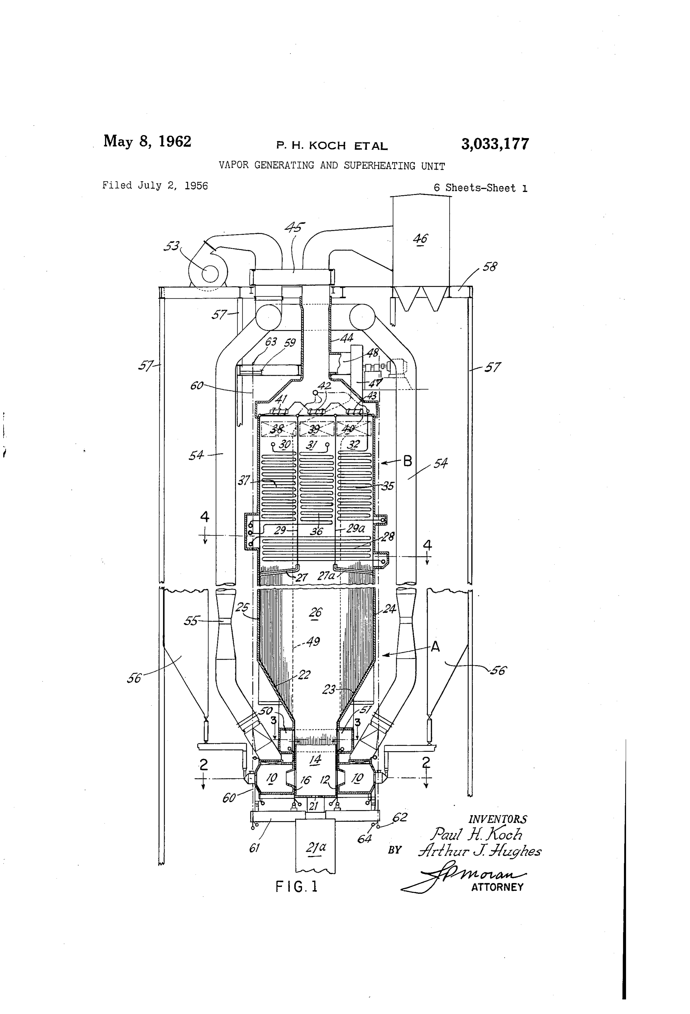
units, and, more particularly, to forced flow once- through FIG. 1 is a partial diagrammatic sectional elevation of steam generating units. a forced circulation once-through steam generator for Forced flow once-through steam generating units have operation at Supercritical pressure in accordance with been operating in Europe for a number of years and most li5 the present invention.
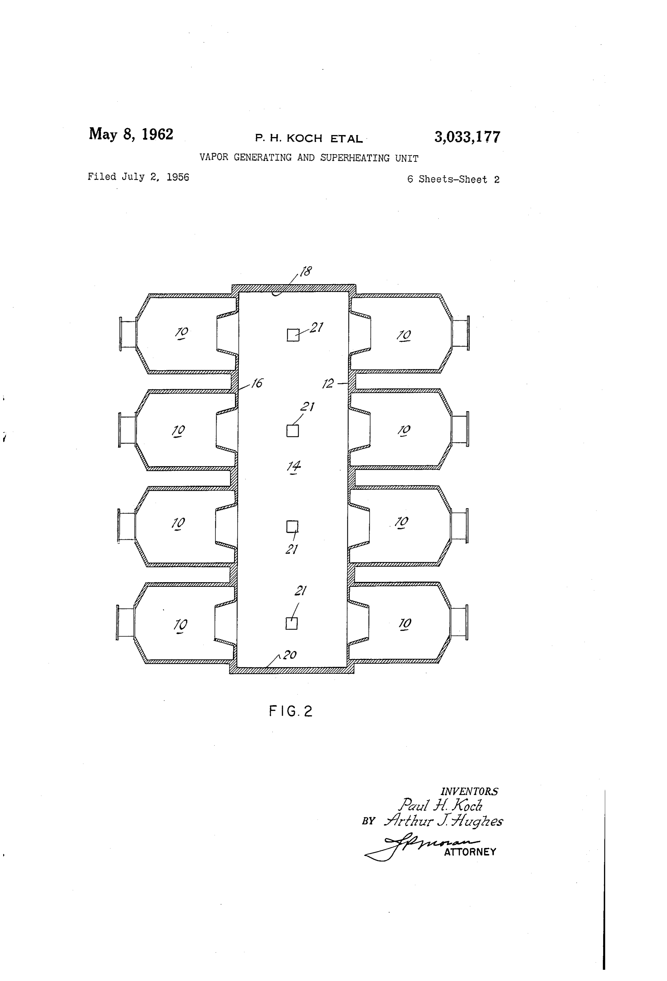
of these units have experienced difficulty of operation due FIG. 2 is a partially diagrammatic plan section taken to corrosion and/or deposition of water-carried solids in on the line 2-2 of FIG. 1.
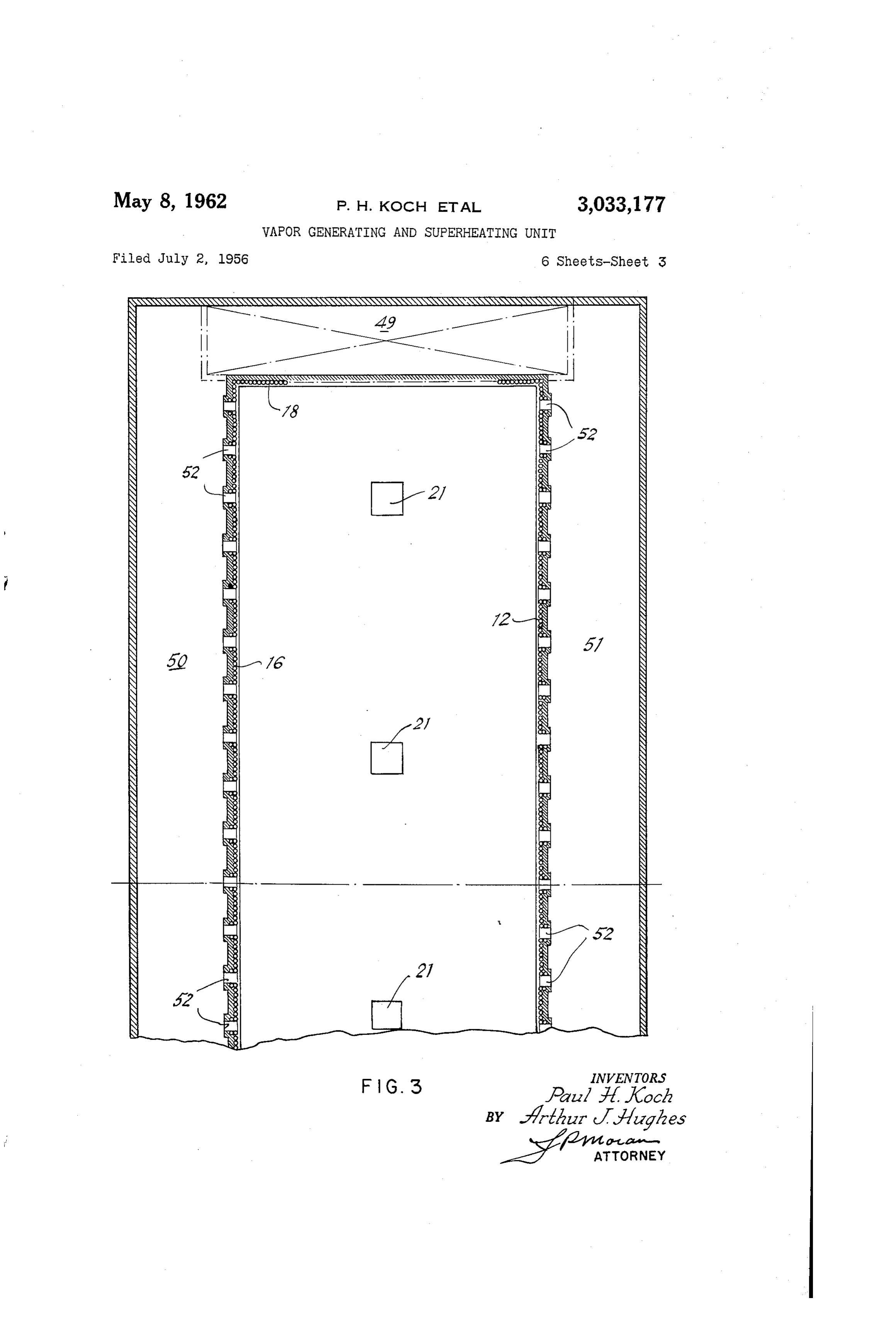
the section of the unit where the liquid is finally con FIG. 3 is a partial plan section (with a portion broken verted to steam. Such a section is usually designated the away) of the gas recirculation arrangement taken on the transition zone. The European units have special pro 20 line 3-3 of FIG. 1.
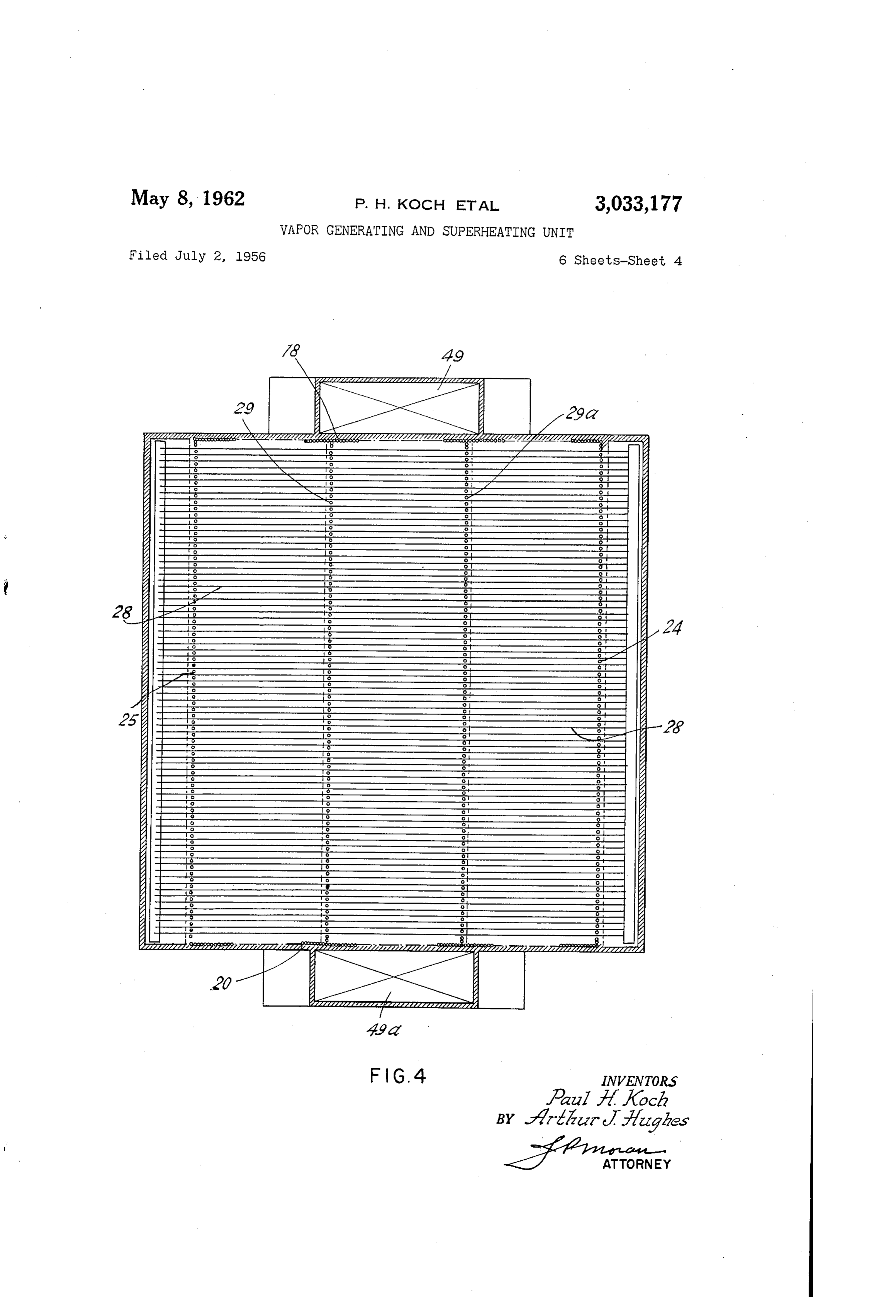
visions for withstanding such corrosion and/or deposi FIG. 4 is a plan section taken on the line 4-4 of tion and under their operating circumstances they have F.G. 1.
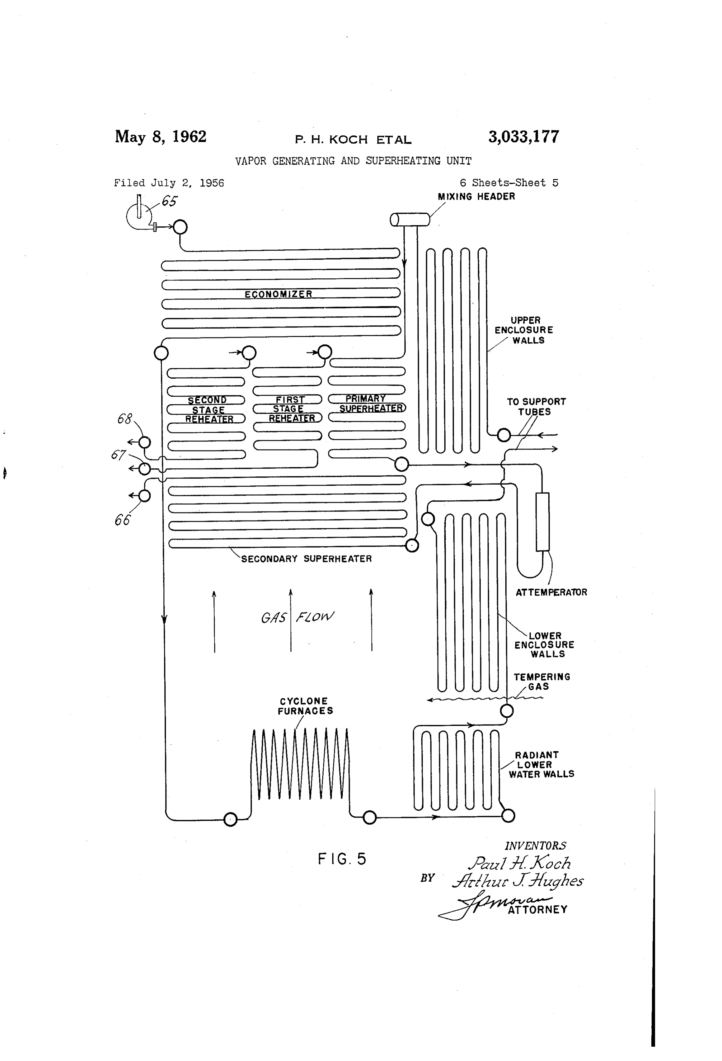
been economically justifiable. However, in this country FIG. 5 is a diagrammatic representation of the vapor such units have never been constructed in large com izable fluid flow arrangement within the steam generator mercial sizes, such as used by the utilities for the gen 25 of FIG. 1.
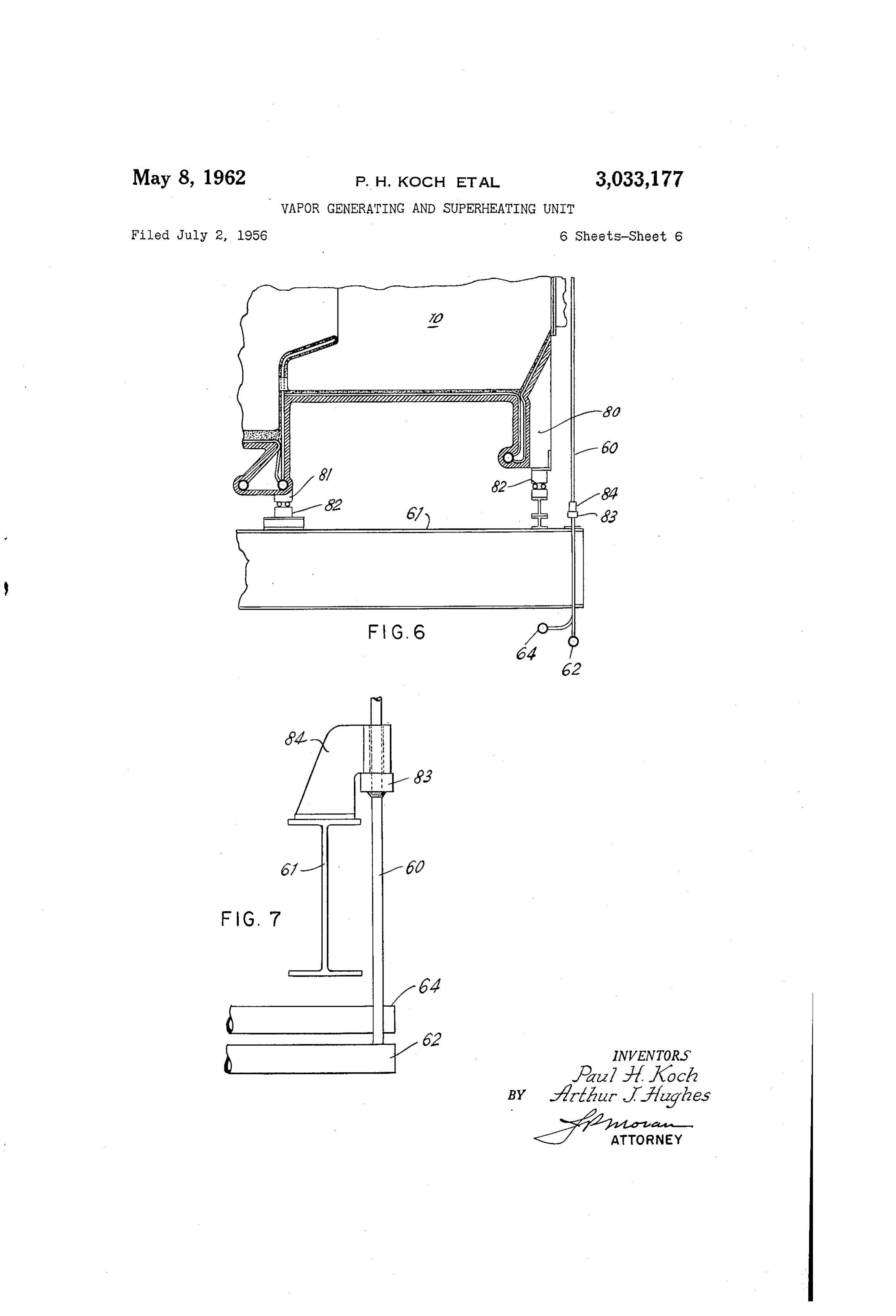
eration of electricity. The U.S. operators have hereto FiG. 6 is a partial vertical section of the details of the fore considered that the problems associated with such cyclone furnace supports; and boilers could not be economically justified in this country. FIG. 7 is a fragmentary view on an enlarged scale However, in the recent past there has been the renewed showing the manner of using the tubular supports of interest in steam generators of the once-through type, and 30 F.G. 6.
particularly, in those which would operate above the criti In the drawings there is illustrated the invention as em cal pressure of 3206 p.s.i.a. Under such conditions the bodied in a forced flow once-through steam generating problem of corrosion and/or deposition is not of the same unit intended for central station use. This particular unit character as previously encountered because above the is designed for a maximum continuous steam flow of critical pressure the fluid changes from liquid to a vapor 35 2,900,000 lbs. per hour at a pressure of 3625 p.s.i.g. and rather suddenly and with no change in density and dur a total steam temperature of 1050 F. at the superheater ing which change there is no boiling to induce corrosion outlet based on feed water being supplied at 4500 p.si.g. or deposition. and with coal firing. The unit includes two steam re It has been previously proposed that once-through heaters, one to raise the temperature of 2,530,000 lbs. of steam generators be operated with the transition zone oc 40 steam per hour at 1,300 p.s.i.g. from 787 F. to 1050° curring in the low temperature convection portion of the F. and the second to raise 1,980,000 lbs. of steam per unit so that corrosion and/or deposition therein will cause hour at 330 p.s.i.g. from 750 F. to 1050 F. a minimum of damage and result in longer life of the With particular reference to FIG. 1 there is shown a unit. vertically extending setting of rectangular cross section The present invention provides a commercial size 45 providing a furnace chamber A and a superjacent con forced circulation once-through vapor generating unit vection gas cooling chamber B. The setting is completely characterized by the transition zone and initial super lined with fluid heating tubes from the lowermost por heating in the radiantly heated enclosure walls of the tion of A. to the uppermost walls of B. The unit is ar setting and provides a means for introducing recircu ranged with eight cyclone furnaces. 10 which are inde lated gas into the furnace chamber of the unit to main 50 pendently fired by crushed or granulated coal and are of . tain a relatively low heat input rate to the transition the general character of U.S. Patent No. 2,357,301. ZOne. Four of the cyclones are arranged to separately discharge More specifically, the invention provides a steam gen combustion products and molten slag through the wall erating unit having a furnace chamber arrangement hav 12 into a small volume portion 14 of the furnace cham ing an upper and lower portion, where slag forming fuel 55 ber A. The other four cyclones are oppositely arranged to is burned in the lower portion wherein the majority of separately discharge combustion products and molten the ash is collected as molten slag and is discharged. The slag into the portion 14 of the furnace chamber. A upper furnace portion is divergently expanded from the through the opposite wall 16. End walls 18 and 20 bound lower portion in a symmetrical manner to provide a cham the setting from top to bottom, each in a single vertical ber for reducing the temperature of the gases and col 60 plane. Thus the walls 12, 16, 18 and 20 form a small lect slag in a dry form prior to the gas entry into a super volume furnace 14 having slag discharge openings 21 in jacent convection chamber within the setting. the lower portion thereof to discharge molten slag re Additionally, the invention contemplates an arrange ceived from the cyclones 10 into a lower slag tank. 21a. ment of cyclone type furnaces arranged on opposite sides The lower portion furnace chamber walls 12, 16, 18 and of the furnace to discharge into an unobstructed small 65 20 are shown diagrammatically but, in practice, they in volume slag collecting chamber and gas recirculation clude a multiplicity of small diameter fluid heating tubes means arranged to discharge cool recirculated products covered by refractory to reduce the heat input thereto of combustion at the exit from said small volume furnace and to maintain the temperature in the cyclones and in to control the resulting furnace gas temperature, such the primary lower furnace 14 above the ash fusion tem. that predominantly all the slag in said furnace gases has 70 perature and to provide conditions conducive to the col solidified prior to entry into the convection passes. lection of molten slag. At the top of the lower portion Additionally, there are provided tubular fluid heated 14, the opposite parallel walls 2 and 16 diverge out
Page 8
wardly uniformly and symmetrically to present sloping 64. This support arrangement will be more completely Walls 22, 23 and thence rise vertically upward as en described hereinafter. - closure Walls 24, 25 which in conjunction with end walls In the operation of the steam generating unit de 18 and 20 form the enclosure walls of the setting in scribed, relatively coarse crushed coal is independently cluding the upper furnace portion 26. and controllably delivered to the separate cyclone fur The convection chamber B is separated from the upper naces 10 wherein the fuel is burned by being whirled furnace portion 26 by the tube screens 27 and 27a and about therein in the presence of combustion air. The which are formed by certain tubes taken from walls 24 resultant burning yields the high heat release rates suf and 25. These tubes rise vertically upward in spaced ficient to maintain a normal means temperature therein relationship to support a secondary superheater 28 which 0. above the ash fusion temperature of the fuel. In the Spans the entire setting width in the lower portion of the operation of this type of cyclone furnace, the ash sepa convection chamber B. Above the superheater 28 the ver rates as molten slag from the combustion gases and flows tical tubes form fluid tight baffles 29 and 29a to define along the bottom of each cyclone furnace into the lower three parallel gas passes 30, 31 and 32. furnace portion 14 and is discharged through the slag A primary superheater 35 of the unit is arranged in 15 openings 21 therein. The combustion products are dis the pass 32 while the first reheater 36 is arranged in charged from the outlet of the cyclone furnace into the central pass 31 and the second reheater 37 is ar the unobstructed lower furnace portion 14 whence the ranged in the pass 30. Above the superheater and re gases pass upwardly towards the upper furnace. The heaters, and in each of the gas passes 30, 31, 32 an econ spacings between the opposite parallel walls 12 and 16 is omizer is disposed. It is divided into three sections : wide enough to prevent the combustion products issuing 33, 39, 40, one in each pass. Gas dampers 41, 42, from the cyclone furnaces on one side from carrying and 43 individually control the gas flow rate in each over into the cyclone furnaces on the opposite side and of the gas passes 30, 3 and 32, respectively. At the an upward velocity is maintained in the lower furnace very top of the unit there is a gas breeching 44 arranged portion 14 which limits the quantity of slag that is car to direct the gas upwardly through the air heater 45 and 25 ried into the upper furnace. The entire surface area thence through the precipitator 45 to the stack (not of the lower furnace chamber 14 is cooled by fluid cooled . shown). tubular members covered with refractory to reduce the A gas recirculation fan 47 is arranged to remove a heat input thereto and to maintain temperatures in the portion of the gas from the breeching 44 via a duct 48 lower furnace portion above the ash fusion temperature and to discharge the gases into supply ducts 49 and 49a 30 so that the molten slag will freely flow out of the slag (FIG. 4) which are on the opposite end walls i8 and 20 outlet 21 and into the slag collection chamber 21a. This of the setting. The gases pass downwardly and into dis refractory terminates at a position adjacent the lower tributing chambers 50 and 51 which run the full width end of the gas distributing chambers 50 and 51. The of the setting above the cyclone furnaces 10 and are upper furnace chamber portion 26 and the convection arranged to receive gas from the supply ducts 49 and 35 chamber B at the top of the setting are cooled by bare 9a. A multiplicity of gas openings or nozzles (prefer tubular members closely spaced and arranged to present ably dampered) 52 are in the opposite parallel walls 100 percent fluid cooled surface to the flowing gases. 12 and 16 and are uniformly distributed across the entire At the juncture between the lower portion 14 and the width thereof to provide recirculated gas arrangements upper furnace chamber portion 26 recirculated gas from which mixes recirculated gas with the combustion prod 40 ducts 50 and 51 is injected into the flowing combustion lucts from the lower portion 14 of the furnace. This con products at a velocity sufficient to cause good mixing trols the gas temperature entering the convection cham upon the subsequent gas expansion caused by the out ber B to a value below the ash fusion temperature. The wardly diverging furnace walls 22 and 23. This expan gas recirculation rate in the unit at maximum continuous sion process occurs abruptly and changes the velocity rating is approximately 40 percent of the gases generat 45 into gas turbulence to thus mix the cool recirculated gas ed by the combustion of the fuel. In addition, to con products within the hot combustion products. This mix trolling the slagging temperature of the combustion gases, ing provides a gas mixture which enters the convection the recirculated gas effects a lower heat input rate to the chamber B uniformly mixed and at a controlled tempera furnace walls 18, 20, 24 and 25 of the upper portion of ture depending upon the rate of recirculated gas prod the furnace A. 50 ucts. Further, as the upper furnace chamber 26 is Combustion air for the cyclone furnaces is supplied very large in volume and is arranged with bare heat by the forced draft fan 53 through the air heater 45 absorbing surfaces, the mixed gases are cooled by ra and down the individual supply ducts 54 which are sym diant heat transmission to the walls, and any slag prod metrically arranged along the length of the setting and ucts contained therein solidify and tend to drop on to which supply each cyclone individually. Within each of 55 the walls, due to cooling and/or turbulence, where the ash these supply ducts there is a venturi section 55 arranged is collected in a dry form. The gas leaves the furnace to meter the air for the control of combustion. Adja chamber A and passes into the convection chamber B cent the air ducts a portion of the coal hoppers 56 are where it passes first over the secondary superheater 28 shown and arranged to supply crushed coal to the cy and subsequently is divided into three controlled streams clones 10. 60 through the individual passes 30, 31, 32 wherein it si The steam generator setting is supported by structural multaneously heats the first reheater 36, the second re steel members having upright members 57, upper cross heater 37 and the primary superheater 35. Each of the three parallel flow streams is controlled by dampers beam 58 and lower cross beam 59. These structural 41, 42, and 43 which proportion the heat absorption of members are of sufficient size and strength to top support 65 the the entire load of the steam generator. A portion of reheaters and superheaters as required by the prime mover (not shown). The gas then passes upwardly the load of the steam generator is supported by a multi through plicity of tubular fluid heated support tubes 60 which are the air heater 45 and precipitator 46 to the stack and a portion of the gas is drawn off by the gas recir connected to upper cross beam 59 and extend down culation system for further delivery to the furnace as wardly to carry the load of a plurality of lower cross 70 previously described.
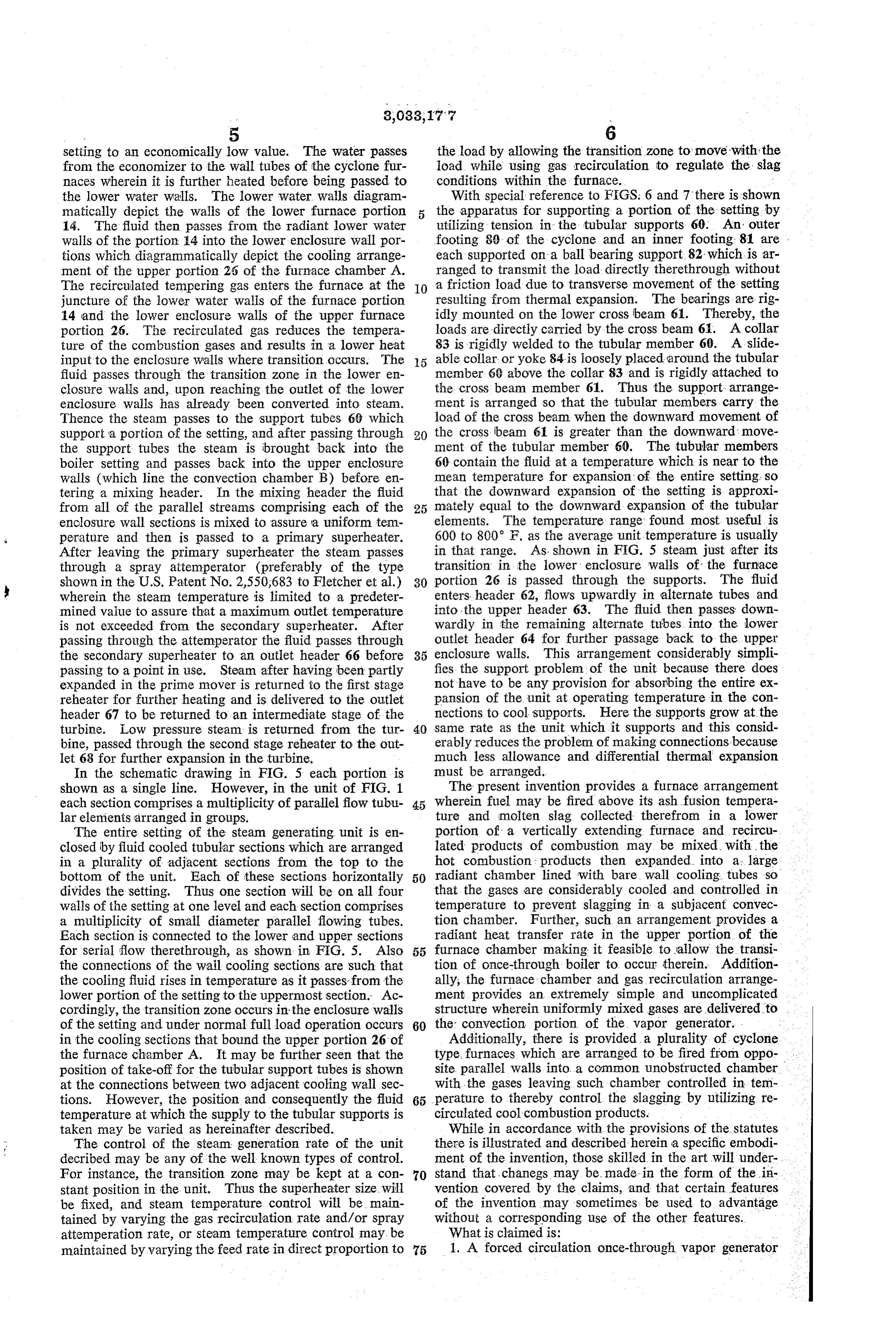
beams 61. These tubular supports 60 and cross beams With particular reference to FIG. 5 the flow of the 59 and 6 are arranged in such a manner that there is vaporizable fluid can best be seen. Water is supplied to a multiplicity of these beams located at spaced positions the economizer by a feed pump 65 at a pressure of ap across the width of the unit. The tubular elements are proximately 4500 p.s.i.g. wherein it flows therethrough connected at top and bottom to the headers 62, 63 and 75 to become partially heated and cools the gases leaving the
Page 9
setting to an economically low value. The water passes the load by allowing the transition zone to move with the from the economizer to the wall tubes of the cyclone fur load, while using gas recirculation to regulate the slag naces wherein it is further heated before being passed to conditions within the furnace.
the lower water walls. The lower water walls diagram With special reference to FIGS. 6 and 7 there is shown matically depict the walls of the lower furnace portion the apparatus for supporting a portion of the setting by 14. The fluid then passes from the radiant lower water utilizing tension in the tubular supports 60. An outer walls of the portion 14 into the lower enclosure wall por footing 80 of the cyclone and an inner footing 81 are tions which diagrammatically depict the cooling arrange each supported on a ball bearing support. 82 which is ar ment of the upper portion 26 of the furnace chamber A. ranged to transmit the load directly therethrough without The recirculated tempering gas enters the furnace at the IO a friction load due to transverse movement of the setting juncture of the lower water walls of the furnace portion resulting from thermal expansion. The bearings are rig 14 and the lower enclosure walls of the upper furnace idly mounted on the lower cross beam 61. Thereby, the portion 26. The recirculated gas reduces the tempera loads are directly carried by the cross beam 61. A collar ture of the combustion gases and results in a lower heat 83 is rigidly welded to the tubular member 60. A slide input to the enclosure walls where transition occurs. The 5 able collar or yoke 84 is loosely placed around the tubular fluid passes through the transition zone in the lower en member 60 above the collar 83 and is rigidly attached to closure walls and, upon reaching the outlet of the lower the cross beam member 61. Thus the support arrange enclosure walls has already been converted into steam. ment is arranged so that the tubular members carry the Thence the steam passes to the support tubes 68 which load of the cross beam when the downward movement of Support a portion of the setting, and after passing through the crossbeam 61 is greater than the downward move the support tubes the steam is brought back into the ment of the tubular member 60. The tubular members boiler setting and passes back into the upper enclosure 60 contain the fluid at a temperature which is near to the walls (which line the convection chamber B) before en mean temperature for expansion of the entire setting, so tering a mixing header. In the mixing header the fluid that the downward expansion of the setting is approxi from all of the parallel streams comprising each of the 25 mately equal to the downward expansion of the tubular enclosure wall sections is mixed to assure a uniform tem elements. The temperature range found most useful is perature and then is passed to a primary superheater. 600 to 800 F. as the average unit temperature is usually After leaving the primary superheater the steam passes in that range. As shown in FIG. 5 steam just after its through a spray attemperator (preferably of the type transition in the lower enclosure walls of the furnace shown in the U.S. Patent No. 2,550,683 to Fletcher et al.) 30 portion 26 is passed through the supports. The fluid wherein the steam temperature is limited to a predeter enters. header 62, flows upwardly in alternate tubes and mined value to assure that a maximum outlet temperature into the upper header 63. The fluid then passes down is not exceeded from the secondary superheater. After wardly in the remaining alternate tubes into the lower passing through the attemperator the fluid passes through outlet header 64 for further passage back to the upper the secondary Superheater to an outlet header 66 before 35 enclosure walls. This arrangement considerably simpli passing to a point in use. Steam after having been partly fies the support problem of the unit because there does expanded in the prime mover is returned to the first stage not have to be any provision for absorbing the entire ex reheater for further heating and is delivered to the outlet pansion of the unit at operating temperature in the con header 67 to be returned to an intermediate stage of the nections to cool supports. Here the supports grow at the turbine. Low pressure steam is returned from the tur 40 same rate as the unit which it supports and this consid bine, passed through the second stage reheater to the out erably reduces the problem of making connections because let 68 for further expansion in the turbine. much less allowance and differential thermal expansion In the schematic drawing in FIG. 5 each portion is must be arranged.
shown as a single line. However, in the unit of FIG. 1 The present invention provides a furnace arrangement each section comprises a multiplicity of parallel flow tubu 45 wherein fuel may be fired above its ash fusion tempera lar elements arranged in groups. ture and molten slag collected therefrom in a lower The entire setting of the steam generating unit is en portion of a vertically extending furnace and recircu closed by fluid cooled tubular sections which are arranged lated products of combustion may be mixed with the in a plurality of adjacent sections from the top to the hot combustion products then expanded into a large bottom of the unit. Each of these sections horizontally 50 radiant chamber lined with bare wall cooling tubes so divides the setting. Thus one section will be on all four that the gases are considerably cooled and controlled in walls of the setting at one level and each section comprises temperature to prevent slagging in a subjacent convec a multiplicity of small diameter parallel flowing tubes. tion chamber. Further, such an arrangement provides a Each section is connected to the lower and upper sections radiant heat transfer rate in the upper portion of the for serial flow therethrough, as shown in FIG. 5. Also 55 furnace chamber making it feasible to allow the transi the connections of the wail cooling sections are such that tion of once-through boiler to occur therein. Addition the cooling fluid rises in temperature as it passes from the ally, the furnace chamber and gas recirculation arrange lower portion of the setting to the uppermost section. Ac ment provides an extremely simple and uncomplicated cordingly, the transition zone occurs in the enclosure walls structure wherein uniformly mixed gases are delivered to of the setting and under normal full load operation occurs 60 the convection portion of the vapor generator. in the cooling sections that bound the upper portion 26 of Additionally, there is provided a plurality of cyclone. the furnace chamber A. It may be further seen that the type, furnaces which are arranged to be fired from oppo- . position of take-off for the tubular support tubes is shown site parallel walls into a common unobstructed chamber at the connections between two adjacent cooling wall sec with the gases leaving such chamber controlled in tem tions. However, the position and consequently the fluid 65 perature to thereby control the slagging by utilizing re temperature at which the supply to the tubular supports is circulated cool combustion products. taken may be varied as hereinafter described. While in accordance with the provisions of the statutes The control of the steam generation rate of the unit there is illustrated and described herein a specific embodi decribed may be any of the well known types of control. ment of the invention, those skilled in the art will under For instance, the transition zone may be kept at a con 70 stand that, chanegs may be. made in the form of the in stant position in the unit. Thus the superheater size, will vention covered by the claims, and that certain features be fixed, and steam temperature control will be main of the invention may sometimes be used to advantage tained by varying the gas recirculation rate and/or spray without a corresponding use of the other features. attemperation rate, or steam temperature control may be What is claimed is:
maintained by varying the feed rate in direct proportion to 75 1. A forced circulation once-through vapor generator
Page 10
comprising tubular fluid cooled walls forming a vertically gas cooling chamber receiving combustion gases flowing extending setting of rectangular cross-section providing upward from said furnace, combustion means including a furnace chamber and a superjacent convection gas a plurality of fluid cooled cyclone furnaces arranged on cooling chamber receiving combustion gases flowing up opposite sides of said furnace chamber to separately dis ward from said furnace, said furnace chamber having 5 charge combustion gases and molten slag into said lower a small volume unobstructed lower portion arranged for portion, structural members for top supporting said set the collection of molten slag and a large upper radiant iting including a plurality of fluid heated vertical tubular portion arranged with bare metal walls for the cooling Support members arranged at spaced positions along the of molten slag to dry ash, said furnace walls having a setting to carry in tension a portion of the support load pair of upright fluid cooled parallel opposing walls in 0 of said setting, a cross beam passing under said cyclone said lower portion which diverge upwardly and then furnaces, ball bearing means on said beam to friction run vertical and parallel to form in part a large sym lessly support said cyclone furnaces, means on said tubu metrical shaped radiant upper portion of said furnace, lar supports for carrying a down loading only of said combustion means providing to said lower portion high beam, and means for passing the vaporizable fluid from temperature products of combustion from slag forming 5 said setting through said supports at a temperature near fuel, means introducing low temperature gaseous prod that of the average temperature of said setting. ucts of combustion which are taken from a point in said 4. A vapor generating unit comprising fluid cooled convection cooling chamber into said furnace adjacent walls forming a vertically elongated furnace chamber the juncture of said lower and upper portions, said fluid having a small volume unobstructed lower portion ar cooled walls horizontally divided into a plurality of verti 20 ranged for the collection of molten slag and a large up cally adjacent cooling sections each arranged for opera per radiant portion arranged for the cooling of molten tion with a fluid temperature higher than a subjacent sec slag to dry ash, said furnace walls having a pair of up tion, each cooling section having a multiplicity of fluid right fluid cooled parallel opposing walls in said lower cooling tubes arranged for parallel flow of fluid therein, portion which diverge upwardly and then run vertical each of said adjacent wall cooling sections above said and parallel to form in a part a large symmetrical shaped lower small volume furnace portion arranged for super radiant upper portion of said furnace above the central heating vapor, and means for flowing high pressure va ly arranged small volume lower portion with the junc porizable fluid once-through said cooling sections in ture of said lower and upper portions providing an abrupt serial flow from the lowest to the highest section of the 30 change in flow area and attendant rapid decrease in gas velocity in said upper portion, combustion means pro setting walls.
2. A forced circulation once-through vapor generator viding to said lower portion high temperature products comprising tubular fluid cooled walls forming a verti of combustion from slag forming fuel, said combustion cally extending setting of rectangular cross-section pro means including a plurality of fluid cooled cyclone fur viding a furnace chamber and a superjacent convection 35 naces arranged with their central axes substantially hori gas cooling chamber receiving combustion gases flowing Zontal on opposite sides of said furnace chamber to sep upward from said furnace, said furnace chamber having arately discharge combustion gases and molten slag a small volume unobstructed lower portion arranged for through said parallel opposite walls into said lower por the collection of molten slag and a large upper radiant tion, and means introducing low temperature gaseous portion arranged with bare metal walls for the cooling of 40 products of combustion which are taken from a point in molten slag to dry ash, said furnace walls having a the vapor generator remote from said furnace into the lower portion of said furnace adjacent the juncture of pair of upright fluid cooled parallel opposing walls in Said lower and upper portions to provide rapid mixing said lower portion which diverge upwardly and then run of the low temperature gases with the high temperature vertical and parallel to form in part a large symmetrical products shaped radiant upper portion of said furnace, combustion chamber. as they rapidly decrease velocity in said upper means providing to said lower portion high tempera 5. A vapor generating and heating unit adapted to ture products of combustion from slag forming fuel, burn a slag producing fuel comprising a setting having said combustion means including a plurality of fluid cooled cyclone furnaces arranged on opposite sides of closing rear front, and side fluid cooled walls, said walls en a radiant section and a vertical superposed con said furnace chamber to separately discharge combustion gases and molten slag through said parallel opposite walls 50 vection heating section having vapor heating means dis into said lower portion, certain tubes from one pair op mary radiation said posed therein, radiation section having a lower pri posing walls extending inwardly and then upwardly to ondary radiationchamber chamber, and a superposed enlarged sec said front and rear fluid cooled divide said convection gas cooling chamber into an upper volume having three parallel upflowing gas passes and ation chamber diverging portion walls adjacent the upper of said primary radi a lower open volume arranged as a single gas pass and 55 structed transition section between theto upper outwardly form an unob and lower separated from said furnace by said inwardly extending chambers, a plurality of laterally extending and spaced tubes, a primary superheater in one of said parallel gas apart cyclone furnaces disposed in the front and rear passes, a first stage vapor reheater in a second of Said walls of said primary radiation chamber, said cyclone parallel gas passes, a second stage reheater in the third furnaces arranged to discharge hot gaseous products of of said gas passes, a secondary superheater substantially 60 combustion directly into said primary radiation cham filling the lower single gas pass of said convection cool ber ing gas chamber and arranged to be heated by all of the Saidsosetting that gas distribution across the setting is enhanced, heating gases, an economizer having three sections with tributed gasesbeing arranged to flow said uniformly dis upwardly therethrough, and means for one in each of said three heating gas passes above the withdrawing lower temperature heating gas from a posi pertinent vapor heater, damper means arranged to in 65 dividually regulate the heating gas flow in each of said tion remote from said radiation section and recirculating three gas passes, and means for providing serial flow introducedthrough the same said radiation section, said gas being into said section below said transition sec of high pressure vaporizable fluid successively through tion whereby the recirculated gas and hot combustion said economizer, cyclone furnaces, lower small volume gases are mixed as they flow from the lower radiation furnace walls, upper furnace walls, convection chamber 70 chamber through the transition section and into the en walls, primary superheater and secondary superheater. larged upper chamber.
3. A forced circulation once-through vapor generator comprising tubular fluid cooled walls forming a verti 6. In a fluid heating unit having a fluid circulation cally extending setting of rectangular cross-section pro system; walls including fluid heating tubes connected into viding a furnace chamber and a superjacent convection 75 said system forming an upright gas flow chamber; a cy
Page 11
clone furnace connected to said chamber and supplying intermediate portion of substantial height and of continu high temperature heating gases thereto; means for top ously increasing horizontal cross-sectional area in the Supporting said unit comprising means for top supporting direction of said upper portion opening at its opposite said walls, and means for carrying the weight of said ends to said lower and upper portions, firing means dis cyclone furnace including a support beam disposed there posed on at least one of the walls of the lower portion under, roll type bearing means on said beam for trans of said furnace and directly supplying to said lower fur mitting the load of said cyclone furnace to said beam nace portion high temperature products of combustion and permitting relative horizontal movement between from slag-forming fuel, a slag outlet from said lower said beam and cyclone furnace, upright tubular support furnace portion, gas recirculation means constructed and means, means for transmitting the load of and securing 10 arranged to conduct heating gases from a position down Said beam to said tubular support means, means for top Stream gas-wise of said furnace to the lower portion of Supporting said upright tubular support means, and means said furnace at a position adjacent the juncture of said for passing fluid through said tubular support means at lower and intermediate furnace portions for mixing with a temperature near to that of the average temperature the freshly generated products of combustion, said inter of said fluid heating tubes. 5 mediate furnace portion being proportioned and arranged 7. A vapor generating unit comprising fluid cooled and of a height sufficient to provide an abrupt decrease walls forming a vertically elongated furnace chamber in gas flow velocity between the lower and upper ends having a small volume unobstructed lower portion ar thereof, rapid and intimate mixing of the recirculated ranged for the collection of molten slag and a large up gases with the freshly generated gases, and uniform dis per radiant portion arranged for the cooling of molten 20 tribution of the resulting gas mixture to said upper fur slag to dry ash, said furnace walls having a pair of up nace portion.
right fluid cooled parallel opposing walls in said lower portion which diverge upwardly and then run vertical References Cited in the file of this patent and parallel to form in part a large symmetrical shaped UNITED STATES PATENTS radiant upper portion of said furnace above the central 25 1,634,084 Ruths ---------------- June 28, 1927 ly arranged small volume lower portion with the junc 2,628,598 Van Brunt ------------ Feb. 17, 1953 ture of said lower and upper portions providing an abrupt 2,730,080 Stallkamp -------------- Jan. 10, 1956 change in flow area and attendant rapid decrease in gas 2,774,339 Junkermann ------------ Dec. 18, 1956 velocity in said upper portion, combustion means pro viding to said lower portion high temperature products 30 2,815,007
of combustion from slag forming fuel, said combustion means including firing means arranged on opposite sides FOREIGN PATENTS of said furnace chamber, and means introducing low temperature gaseous products of combustion which are 1,065,655 France ---------------- Jan. 13, 1954 taken from a point in the vapor generator remote from 1,068,954 France ---------------- Feb. 10, 1954 said furnace into the lower portion of said furnace adja 523,870 Great Britain ---------- July 24, 1940 cent the juncture of said lower and upper portions to 726,244 Great Britain ---------- Mar. 16, 1955 provide rapid mixing of the low temperature gases with 727,218 Great Britain ---------- Mar. 30, 1955 the high temperature products as they rapidly decrease OTHER REFERENCES in velocity in said upper chamber. 40 8. A vapor generating unit comprising walls includ Combustion, April 1955, pages 57 to 60. ing radiant heat absorbing fluid cooled tubes forming an Steam, by The Babcock & Wilcox Co., 37th ed. of 1955, upright substantially unobstructed furnace, said furnace page 28-6.
having a small volume lower portion of substantially uni Steam, by The Babcock & Wilcox Co., 37th ed., third form horizontal cross-sectional area throughout its height, 45 printing of 1955, pages 28-9; published by Geo. McKib a large upper portion above said lower portion, and an bin & Son.
Provenance
- Collection
- Cited prior art
- Original PDF
- patentimages.storage.googleapis.com →
- Filed
- 1956-07-02
- Pages
- 11
- Method
- pdftotext (the PDF's own text layer) + pdftoppm 300dpi page scans
- Source
- Google Patents bibliographic record
- Granted
- 1962-05-08
- Inventors
- Paul H Koch; Arthur J Hughes; Babcock and Wilcox Co
- Transcribed from
- patentimages.storage.googleapis.com →