patent · US3652431
Method of operating an electrolysis cell for the production of gases under hydrostatic pressure
28 March 1972
Page 1 — bibliographic record
United States Patent (15) 3,652,431 Reynolds (45) Mar. 28, 1972 54) METHOD OF OPERATING AN 3,208,884 9/1965 Jensen................................... 136/178 ELECTROLYSS CELL FOR THE 2,930,828 3/960 Herold................................... 136/181 PRODUCTION OF GASES UNDER 2,733,389 1/1956 Ellison................................... 317.1230
HYDROSTATIC PRESSURE
Primary Examiner-John H. Mack 72 Inventor: Julian Louis Reynolds, 551 1 Cary Street Assistant Examiner-R. L. Andrews Road, Richmond, Va., 23226 Attorney-G. William King and Norman D. Dawson 22 Filed: Mar. 12, 1970 57 ABSTRACT 21) Appl. No.: 18,933 A method of carrying out an electrolytic process for produc Related U.S. Application Data ing gases in an electrolyzer comprising at least one electrolytic cell and a containment vessel therefor, said method compris 63 Continuation-in-part of Ser. No. 503,693, Dec. 23, ing supplying electric power to said electrolyzer from an exter 1965, abandoned. nal source during operation thereof, subjecting said vessel to an external superatmospheric hydrostatic pressure, continu 52) U.S. Cl................................204/129, 204/275, 136/166 ously charging said electrolyzer with electrolyte under pres 51 int. Cl......................................C01b13/06, HO1m 1100 sure and while operating pressure of the continuous elec (58 Field of Search................ 136/178,166; 204/1, 59, 194, trolytic system by collecting the produced gases external to 204/265,277, 129, 263,275 said electrolyzer and external hydrostatic pressure against said 56) References Cited collected gases generated and being in fluid communication with the interior of said electrolyzer so that said internal and
UNITED STATES PATENTs external pressures are approximately the same during said operating.
3,391,029 7/1968 Orsino................................... 136/166 3,390,017 6/1968 Hennigan............................... 136/166 3 Claims, 9 Drawing Figures
ELECTROLYTE PREPARATION
AND TREATMENT
POWER FEED WATER REAMENT f
SUPPY AND SUPPLY - - - --
BUS BAR EECROYE
SOAON FEED Z Mix TANK
Ocx SWTC
RANSFORMER
WAER 2
FTER
RESISTOR
CRCUIT BREAKER
WATER/LAND O5
STITUTITILITITTEIT
Page 2
Drawing sheet — no readable text.
Page 3
Drawing sheet — no readable text.
Page 4
Drawing sheet — no readable text.
Page 5
PATENTED MAR 28 1972 3, 652, 43.
POWER FEED WATER TREATMENT ELECTROLYTE PREPARA PRODUCT SUPPLY AND SUPPLY TION TREATMENT RECOVERY
FEED
WATER t
- I - bus BAR
%He Zvi 85 ECTROLYE. A
CARON W.
O TRANSFORMER F LTER %
N CRCUIT BREAKER
SOLATON SW.
WisTARTING rid
F LTER
circulatiNGL
PUMP
(LAND surFACE
COONG
ELECTROLYZER
I62-il r(163 NSSSNSNNYSSSSSSSSaxasas SaaSassassian
72 yaHI 72A S. R e GSNR
PR ESS NSSSSSSSSSy
BoTTOM
EQUALIZER
I NWE Nitro R.
JULIAN Louis REY NOLDs
Six 77 a22222 Atto RNEY
Page 6
Drawing sheet — no readable text.
Page 7
METHOD OF OPERATING ANELECTROLYSS CELL Briefly, the present invention overcomes the above-men FOR THE PRODUCTION OF GASESUNDER tioned, and other, disadvantages of high pressure electrolytic HYDROSTATIC PRESSURE units, and in addition, provides several advantages. In ac cordance with the present invention, a process is provided in
This application is a continuation-in-part of application Ser. 5 which electrolytic units are subjected not only to internal pres No. 503,693 filed Oct. 23, 1965 now abandoned. sure but also to the super-atmospheric pressure of an external This invention relates to novel processes for producing environmental medium in which the cell containment vessel chemical compounds and compositions, and to novel ap resides during operation. Among the advantages that may be paratus therefore. More particularly this invention relates to achieved is an economical benefit over previously known elec novel processes for producing chemical substances in a pres O trolyzers, in both construction and operation. Moreover, in a surized environment, and apparatus therefore. medium such as water, the produced gases are at substantially The basic principles of this invention are particularly useful the same pressure as the medium and do not tend to leak out, in electrolytic processes carried out in pressurized environ but even if they did, a dangerous condition would not be im ments, and are hereinafter described in connection with elec mediately created. Thus, in addition to operating economies, trolytic production of hydrogen and oxygen, although as will 15 insurance and equipment costs may be saved. become apparent from the following, these same basic princi In particular, the preferred embodiment of the present in ples may be utilized broadly in many chemical and elec vention has, as its basic principle, maintaining the internal and trochemical processes, particularly those favored by high external containment vessel pressures substantially equal by, pressures, and insofar as they are applicable in such other 20 for example, placing a containment vessel in a fluid medium processes, are intended to be embraced by, and included in, (such as water) having a pressure head at the depth at which this invention. the vessel resides, approximately equal to the desired internal There have been several previously known endeavors re operating pressure of the electrolytic unit, or by utilizing a lated to pressure electrolysis wherein internal pressure en novel containment vessel which will permit the fluid pressure vironments have been created artifically in expensive, heavy 25 head to establish substantially the same pressure inside the metal walled pressure vessels operating in plants where sub vessel as outside, whereby the stresses normally created in the stantially ambient conditions existed. One aspect of this inven containment vessel by the operating internal pressure will be tion, broadly stated, is that it differs from such endeavors by substantially offset by the external pressure of the fluid medi making use of geological features of the earth's surface and um. The external pressure medium is not restricted to a fluid subsurface wherein high pressure conditions exist and may be 30 medium, but may include a gas medium or in some instances a utilized as an environment for carrying out chemical or elec solid medium or various combinations thereof. As a result of trochemical processes, the externally applied pressure, the containment vessel may be Production of hydrogen and oxygen by electrolysis in a constructed of thin, relatively inexpensive materials, large pressurized containment vessel has several advantages over electrode space may be used, and in general all of the ad prior methods, and has been carried out on a commercial 35 vantages of atmospheric pressure units may be achieved while scale for some time. For example, many of these plants use at the same time the unit may be operated under pressure to electrolyzers containing bipolar cells which must undesirably also achieve all of the advantages of the pressurized unit. be relatively small, usually approximately one-fifth the size of The electrolytic cell construction useful in a pressurized the more conventional monopolar cells and which produce containment vessel in accordance with this invention may be hydrogen at pressures in the order of 30-200 atmospheres 40 of any suitable known construction, and is not a critical factor gauge. Nevertheless, certain advantages may be derived by of the invention. Thus it is possible to utilize the principles of operating under pressure, for example, by operating in a pres this invention with electrolytic cells having separate elec surized containment vessel, the cell will require lower voltage trodes, or as unit cells containing two anodes and one cathode (the voltage decreasing as pressure increases), enable the 45 or vice versa, or as multiple cells, diaphragm cells, bell-jar electrolyzer to carry higher amperage thereby reducing volt cells, etc.
age of the cells still further since they will be able to tolerate Accordingly, it is a primary object of the present invention higher temperatures, operate with less specific power con to provide a novel process, and novel apparatus therefor, for sumption than the normal 0.130 to 0.145 kwh/scf level of at carrying out chemical and electrochemical processes under mospheric pressure electrolyzers, utilize energy more effi 50 pressure, and in particular, to provide the same by utilizing ciently and require less cooling than atmospheric pressure pressure of an external medium to offset the disadvantages of electrolyzers, and even save mechanical compression costs by internal pressures in containment vessels, normally encoun delivering the produced gases at a pressure substantially equal tered in chemical and electro-chemical processes. to the electrolyzer operating pressure. The latter may be of Another object of the present invention is to provide a particular advantage where it is desired to deliver a gas under 55 processing system in which a containment vessel is placed in a pressure into another chemical process, for example, as is medium, the pressure head of which is utilized to raise the desirable in synthetic production of ammonia to effect savings containment vessel internal pressure as well as the external in compression and large storage vessels. pressure or only to offset internal pressure produced in the While the foregoing advantages may be achieved by pres vessel by previously known pressurizing methods. sure electrolysis, nevertheless there are many problems re 60 Still other objects of super-atmospheric present invention lated to the pressurization which produce economic and are to provide: non-existent operating difficulties. Of prime importance is the maintenance A novel process for superatmospheric pressure electrolysis of a completely sealed operating system. Because of the condi of water to produce hydrogen and oxygen in a containment tions under which an electrolytic cell works, even a minute vessel having a low or nonexistent pressure differential leak to atmosphere of one of the gases will cause differences in 65 between its interior and exterior; pressure between the anode and cathode spaces, possibly per A novel process of creating super-atmospheric pressure mitting the gases to intermix and create a dangerous situation. conditions in an electrolyzer containment vessel; Thus the containment vessel must be constructed from suita Novel apparatus comprising, in general, containment ves ble high quality materials with precision to prevent leakage, sels adapted to be located in or under an external medium and and yet permit the produced gases to be drawn off after disas 70 establish the pressure of the internal medium without per sociation at the proper rates to maintain a balanced system. mitting said external medium to intermix with the internal Considering the foregoing, high pressure electrolyzers, as medium which constitute the contents of the vessels; compared to atmospheric electrolyzers, are presently required Processes and systems supplying the aforesaid containment to have thick, expensive containment vessel walls and to use 75 vessels with raw materials, and removing the process products relatively small electrode surfaces. under pressure;
Page 8
Processes for producing chemicals and chemical composi Electric power is supplied by a high voltage three-phase AC tions under pressure by chemical and electrochemical means circuit. A transformer first reduces the high voltage to a value utilizing reaction vessels pressurized by an external medium; equal to the input voltage rating of the subsequent rectifier Apparatus for removing and storing the products produced which converts the three-phase AC current into DC current. under pressure in storage vessel similarly situated in a super Silicon rectifiers are preferable because of their high efficien atmospheric high pressure medium or otherwise adapted to cy, their rugged construction and ease of operation. The am maintain the products under pressure until release for trans perage of the DC current for electrolysis is kept constant by an mission or consumption; infinitely variable control, because the electrolysis unit has a Processes and apparatus for electrolysis of water under high very flat operating characteristic. Control is accomplished by pressure in an external medium such as water, the pressure 10 means of a load tap-changing switch with continuous trans head of which at the containment vessel depth establishes a ducer control, within the range of approximately two trans pressure therein approximately equal to that of the external former taps. A circuit-breaker is installed between the rectifi medium.
er and the electrolysis unit to disconnect the electrolysis unit
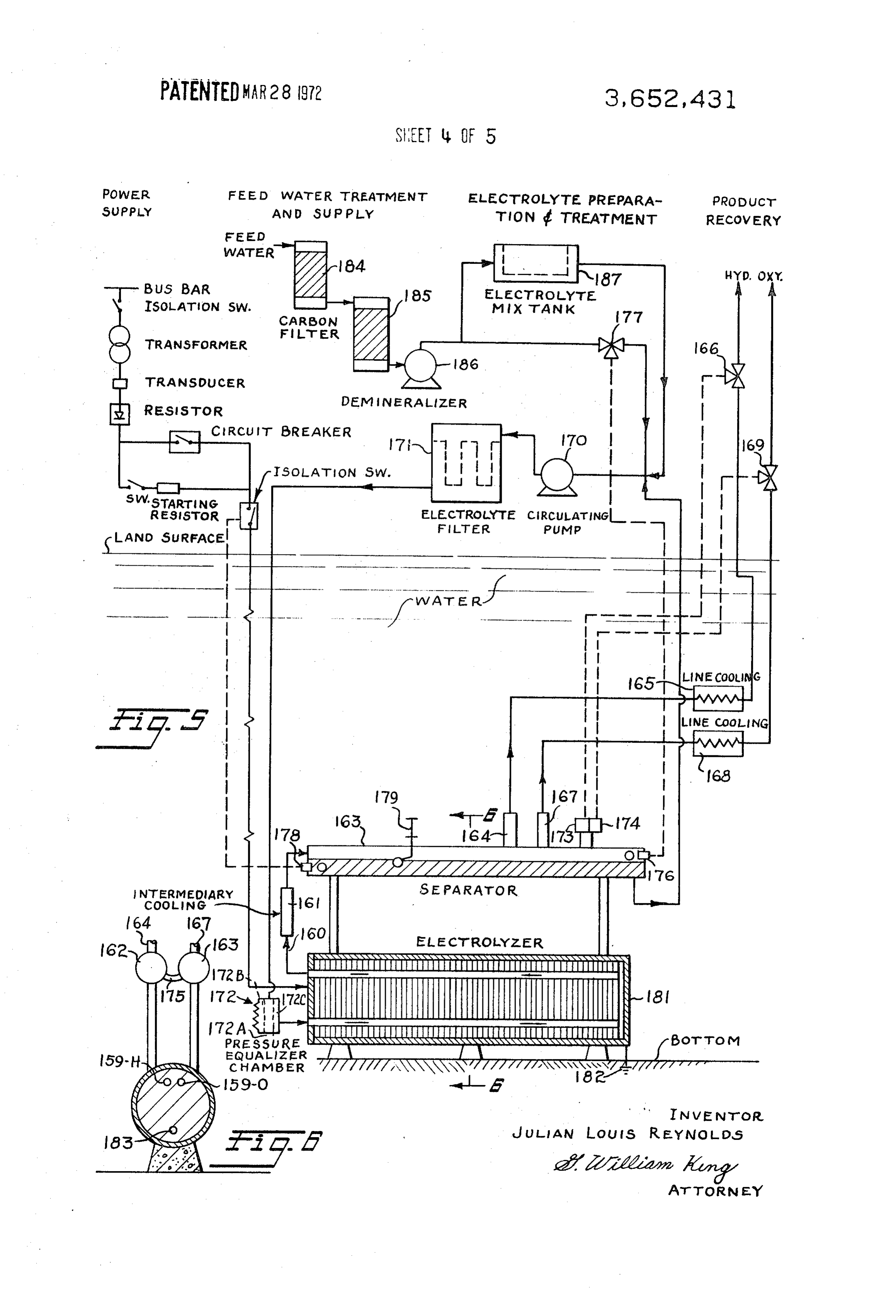
Various other objects, advantages and features of the inven (under load) from the circuit. A low resistance resistor in se tion will become apparent to those skilled in this art from the 15 ries with a contractor is connected in parallel with this circuit appended claims and following description of the best mode of breaker. The purpose of this resistor is to avoid excessive cur carrying out the present invention, and modifications thereof, rent surges during starting when the electrolysis unit is not yet taken in connection with the accompanying drawings wherein; polarized. After a certain minimum electrolysis voltage has FIG. 1 is a schematic drawing illustrating an electrolyzer been reached, the resistor is short circuited by the circuit positioned on the bottom of a body of water with flow sheetin 20 breaker. The starting resistor also eliminates the necessity of dications of the system for operating the same. FIG. 1-A is an providing the rectifier with a large reserve capacity; since the end view of the electrolyzer shown in FIG. 1. possibility of large current surges no longer exists. The electri FIG. 2 is a schematic drawing of an electrolysis plant in ac cal equipment is supervised from the surface in a remotely cordance with the present invention, shown in conjunction 25 located central control room.
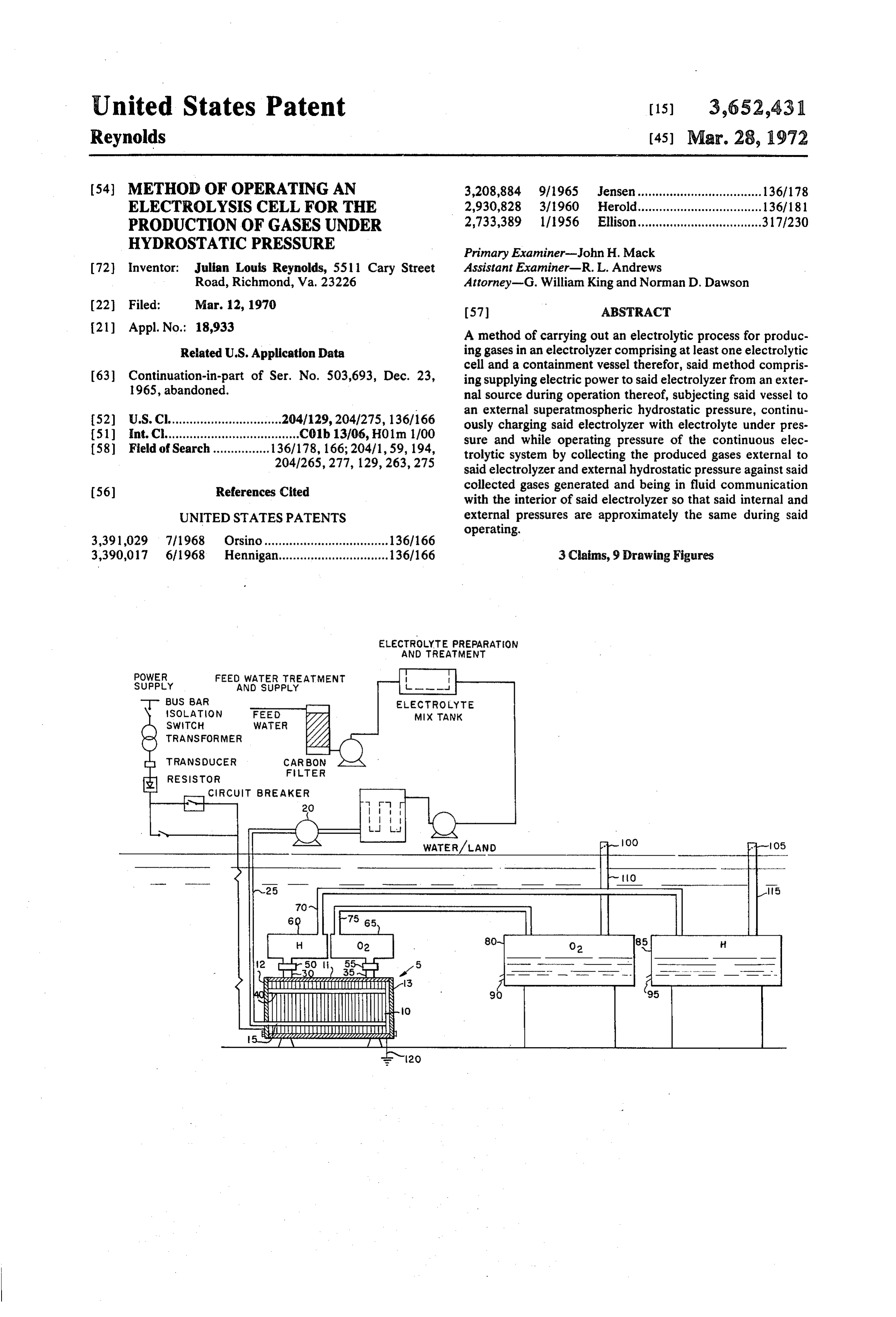
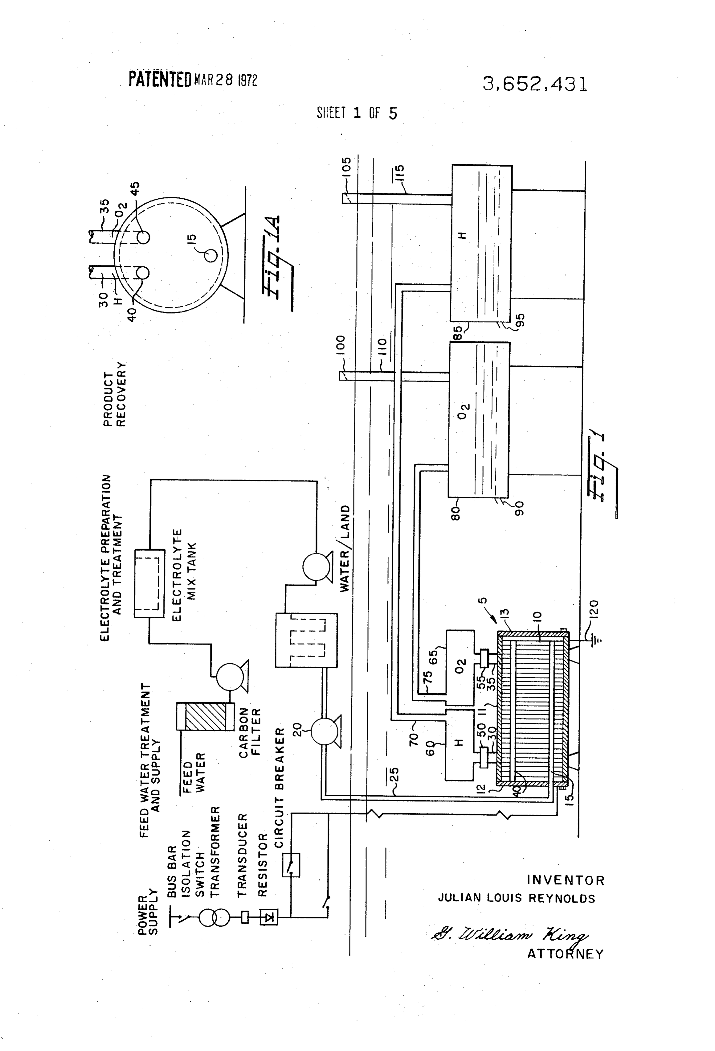
with a plant for producing synthetic ammonia utilizing the The arrangement illustrated in FIG. 1 shows one electrolysis electrolysis products as feed materials; unit 5 whereas in actual practice multiple units would very FIG. 3 is a diagrammatic side elevation illustration of elec likely be employed. Each unit is composed of multiple cells in trolysis unit constructed in accordance with the principles of dicated generally as 10.
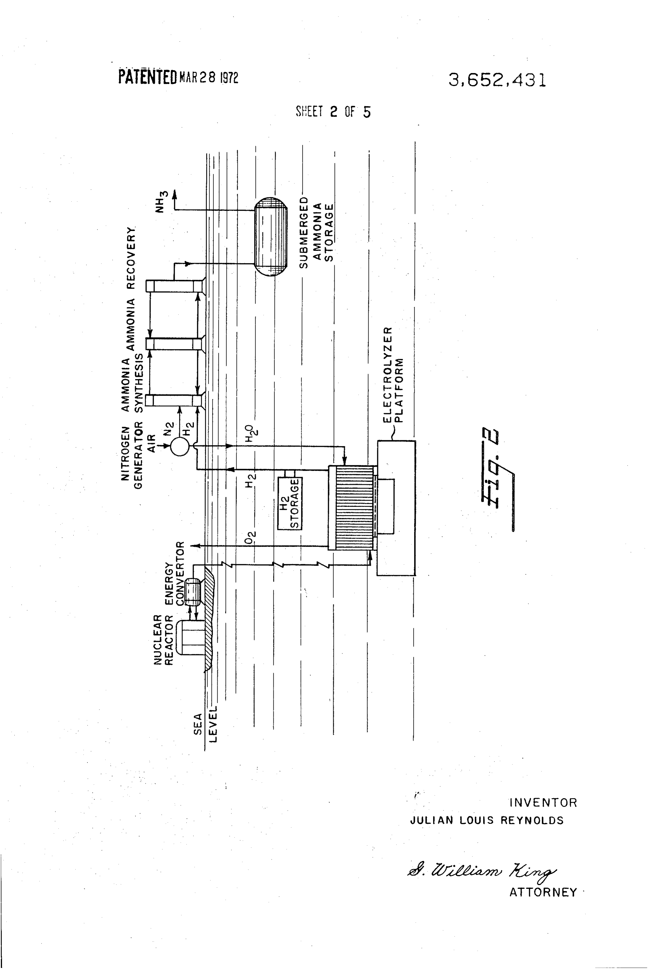
this invention with detailed portions of the unit bottom wall 30 The feed water which is pumped into the electrolysis unit to being in section; makeup the electrolytically dissociated water must be of op FIG. 4 is a bottom plan view of the unit illustrated in FIG. 3, timum purity because contaminants would be retained in the illustrating details of the bottom wall of the unit; electrolysis unit during electrolytic dissociation of the water, FIGS. 5 and 6 illustrate another electrolyzer set up under where they would become concentrated and ultimately Water; 35 disturb the electro-chemical reactions. In this respect the con FIGS. 7 and 8 are diagrammatic side elevation views of elec ditions in the electrolysis unit are the same as in any at trolyzers positioned in land cavities and adapted to operate in mospheric unit, The preheated water passes through an ac accordance with principles of this invention. tivated carbon filter and through a demineralization unit When an electric current is passed through water, hydrogen where the water is demineralized to the extent that it has a ions migrate to the negative electrode (cathode) where they specific resistance of 1 - 10 megohm X cm. The efficiency of
combine with electrons to form hydrogen atoms, which then demineralization is supervised automatically by conductivity unite to produce hydrogen molecules that escape from the control of the water. The demineralized water is supplied by water as bubbles of hydrogen gas. At the same time oxygen pump 20 to the electrolysis unit in accordance with require ions migrate to the positive electrode (anode) where they lose 45 ments. A pump such as 20 is placed in the line to insure that electrons and combine to produce water molecules and ox the electrolyzer can be charged with electrolyte at all times, ygen atoms which combine to form oxygen molecules and also pump 20 being capable of generating pressures in electrolyte escape from the water as bubbles. Because of the low electri line 25 sufficient to perform this function. cal conductivity of water, solutions of sodium hydroxide or Electrolyzer 5 is provided with a containment vessel of 4 potassium hydroxide with distilled water have been conven 50 inch thick stainless steel having a cylindrical casing 11 held tionally employed in lieu of pure water for the electrolytic between end plates 12 and 13. The electrolyte is pumped production of hydrogen and oxygen. Water electrolysis units directly into channel 15 which is in communication with all under atmospheric pressure produce relatively large gaseous cells 10 and delivers electrolyte thereto. Line 25 is open into bubbles and other conditions resulting in high cell voltage the electrolyzer at all times and at all times contains elec requirements. As pointed out above, the actual operating volt trolyte under pressure equal to that of the system as will be age of commercial cells is ordinarily in the range of 2.0 to 2.3 55 described. It is well known that hydrogen and oxygen gases volts at atmospheric conditions. In commercial cells operating can be collected and taken from an electrolyzer from two at atmospheric conditions, power consumption in terms of separate outlets and these are provided at 30 and 35 respec direct current generally runs between 130 to 145 kwh per tively which are stainless steel tubes taped directly into collec 1,000 scf of hydrogen produced. In most instances, direct cur 60 tion channels 40 and 45, the hydrogen outlet 30, and the ox rent is obtained by rectification of alternating current, and ygen outlet 40.
power consumption is therefore 160 to 180 kwh per 1,000 scf In this completely continuous system ducts 30 and 35 pass on an alternating current basis. the produced gases into intermediate coolers 50 and 55 and Referring to the drawings in FIG. 1, the best mode of carry then into separator-collectors 60 and 65. Open ducts 10 and ing out the invention is illustrated. In FIG. 2 a synthetic am 65 15 are provided and extend from collectors 60 and 65 to monia plant is shown in conjunction with the water electroly storage vessels 80 and 85. The latter are large storage com sis process to illustrate the usefulness of the present invention partments which contain a very heavy material such as sand, in other chemical works, as its general applicability will concrete or the like to firmly secure them on the bottom and become apparent. thereby offset any buoyant effects of the gases introduced The electrolyzer can be any one of many presently available 70 therein. The storage compartments are freely open to water units. The preferable unit is of a bipolar Zdansky-Lonza thru openings 90 and 95 which are positioned at a level ap design and even though much of the following is available a proximately the same as the top of the electrolyzor cells and detailed description of various aspects thereof is given. The the electrolyte located therein. Being open, the tanks can be electrolyzer 5 is set in a submerged position with its accom gradually filled with water and sunk into place. Ducts 30 and panying shore and surface based auxiliary equipment. 75 35 conduct hydrogen and oxygen into intermediary cooling
Page 9
S 6 units 50 and 55 which are preferably stainless steel plenum electrolyte pumped into the unit and started. Excessive liquid chambers with one or more baffles to promote direction or electrolyte will be forced into the storage compartments change before entering separator-collectors 60 and 65. The and from there into the sea.
separator-collection chambers are similarly provided with one The DC current is supplied via bus bars to the electrolysis or more baffles extending partially from side to side effecting 5 unit at the front end plate 12 which is the positive pole. The one or more direction changes and generally separating elec discharge of DC current, i.e., the negative pole is at the back trolyte. Additional electrolyte is separated as the hydrogen plate 13 of the cell block.
and oxygen travel upwardly inducts 70 and 75 to storage com Before commissioning the plant, an appropriate quantity of partments 80 and 85. Separation of the electrolyte is not criti electrolyte corresponding to the holding capacity of the elec cal in this system and may be eliminated entirely so that en- O trolysis unit is prepared in tank. Solid caustic potash is poured trained electrolyte in the produced gaseous material is into the hopper of the preparation tank and dissolved with delivered into the storage compartments where it may feed water. After it is dissolved, the electrolyte is admitted to separate from the gases and fall into the water in the storage the electrolysis unit. Before the electrolyte enters the electrol compartment. ysis unit it passes through filter to ensure that the electrolyte is From the foregoing it can be seen that the system is open 15 clean.
from a point down-line from pump 20 through the electrolyzer All component parts of the electrolysis unit, except the 5, outlet ducts 30, thru storage compartments 80 and 85 up to cells, are grounded through ground 120. The electrolysis unit valves 100 and 105 in open outlet lines 110 and 115. The pres therefore has no pipe or other connections which have to be sures exerted on the system are a balance between line pres 20 insulated electrically. The problem of suppression of leakage sure from pump 20 and water pressure acting on the gases in current at such connections, which is experienced with other tanks 80 and 85. The seawater will at all times be available to types of electrolyzers and which generally creates a considera the interior of the storage tanks and therefore will always ble corrosion hazard, does therefore not exist with the subject create pressure approximately equal to the pressure of the electrolysis unit.
ocean at the depth of the storage tanks and, more particularly, 25 Each cell is sealed on both ends by embossed steel-plate at the depth of the gas/water interface inside the storage com walls which are nickel-plated through-out and inserted into partments. In this manner, the pressure of the exterior en annular frames. Nickel-plated and activated steel wire gauze is vironment in which the electrolyzer is operating is exerted placed on the anode and cathode side of the embossed plate to throughout the entire electrolyte system. The storage tanks serve as electrodes. Anodes and cathode compartments are are positioned so that the level of the gas/water interface 30 separated by laminated frames of pure asbestos. The cell therein is at all times above the top of the electrolyte level, frames are isolated from each other by teflon covered sealing which is in the electrolyzer unit. This is to avoid creating an rings. Entering through duct 15 the electrolyte first passes to excessive pressure in the electrolyzer unit that might other the cathode side of the cells, and a portion of it then continues wise occur if the storage tanks or the gas/water interface were to flow through openings in the embossed plates to the anode at a level lower than the electrolyte. By permitting the sea- 35 side. The electrolyte-gas mixture flowing upwards through the water to exert pressure on the gases produced in the storage cells is collected at the cathode side in the hydrogen duct and chambers, the internal pressure of the electrolyzer is equalized at the anode side in the oxygen duct, and carried off. Due to to that of the exterior environment in which it resides. If for the high working pressure of the electrolysis unit because of its any reason excessive internal pressure in the electrolyzer is submerged location and the resulting low specific volume of created, gases in the storage chambers will be pushed to the 40 the gases, the cells can be of very narrow construction. bottom of the storage tanks and out through seawater outlets The cells of the electrolysis unit are assembled in blocks in 90 and 95 and lost, thereby preventing destruction of the the workshop. The cell blocks are delivered to the site in this equipment. From the foregoing it can be seen that the concept preassembled condition where the connecting lines are at of equalizing the internal and external pressures of the elec . 45 tached and they merely have to be lowered into place and trolyzer is achieved while, at the same time, a novel process grounded. This procedure provides for simple, quick and de which is completely continuous and requires practically no pendable installation and recovery of the electrolysis units and shut-down or cleaning is effected. minimizes the offshore operations. All materials should, of In operation, after commissioning electrolyte is continu course, be selected to withstand the external environment, ously available to the electrolyzor at a pressure sufficient to 50 water for example, or the materials should be coated or other maintain a full capacity of electrolyte in the unit at all times. wise protected from any anticipated deleterious effects Gases which are produced consume electrolyte and move into thereof.
the storage chambers. The latter are ship size for large units. Individual units can have nominal capacities ranging As gases are produced more electrolyte automatically is between 5,600 - 24,500 standard cubic feet of hydrogen per available and in the event excessive pressures are created in 55 hour. Larger units can be built and multiple units can be ar the pressure sensors in line 25 relay the information to the sur ranged in parallel. Purities of the hydrogen produced may vary face where power is cut off. All inlet and outlet connections between 99.8 to 99.9 percent on a volume basis and the ox and lines for power, electrolyte, products of the electrolyzer, ygen purity may vary between 99.3 to 99.5 percent. Pressure etc. are of the same construction as utilized for a surface unit, of the gases is a function of the depth to which the electrolysis being pressure tight and capable of resisting corrosion. In un- 60 unit or units are placed.
derwater units commercially available brass or stainless steel As explained earlier, any kind of pressure cell can be used materials are particularly useful. with the principles of the invention. Thus, the cells may be, for in the storage tanks, the gas/water interface can have a example, of the type used in the well-known cells known as the material floating on the water to separate the water and gas if Knowles Cell, Fauser Cell, Bamag Electrolyzer, Pechkranz desired. Under very high pressures, absorption of gas in the 65 Electrolyzer, etc., described and illustrated in an article by C. water may cause some of the latter to be lost. The material E. Bowen, "The Production of Hydrogen and Oxygen By The may be a layer of plastic as a sliding piston in the tank, or a Electrolysis of Water,' Journal Institute Electrical Engineers layer of oil or other suitable material. (London), Vol. 90, No. 1, pp. 474-85. Other suitable cells are In the case of a surface unit the gas compartments of the of the type shown in Zdansky U.S. Pat. No. 2,881,123, for ex separators are filled with nitrogen, after which the DC current 70 ample, modified to include larger electrode surfaces and less supply is opened. This permits commissioning within a few exterior ring-like portions.
minutes and also provides for absolute safety. This process can In FIG. 2, a source of nuclear energy is shown for producing be utilized in the present system if desired; however, the elec steam and creating direct current power by means of turbines trolyzor and chambers need only be filled with a non-com and generators and referred to generally as an energy conver pressible liquid as they are placed at the depth intended and 75 tor. The nuclear reactor and energy convertor apparatus are
Page 10
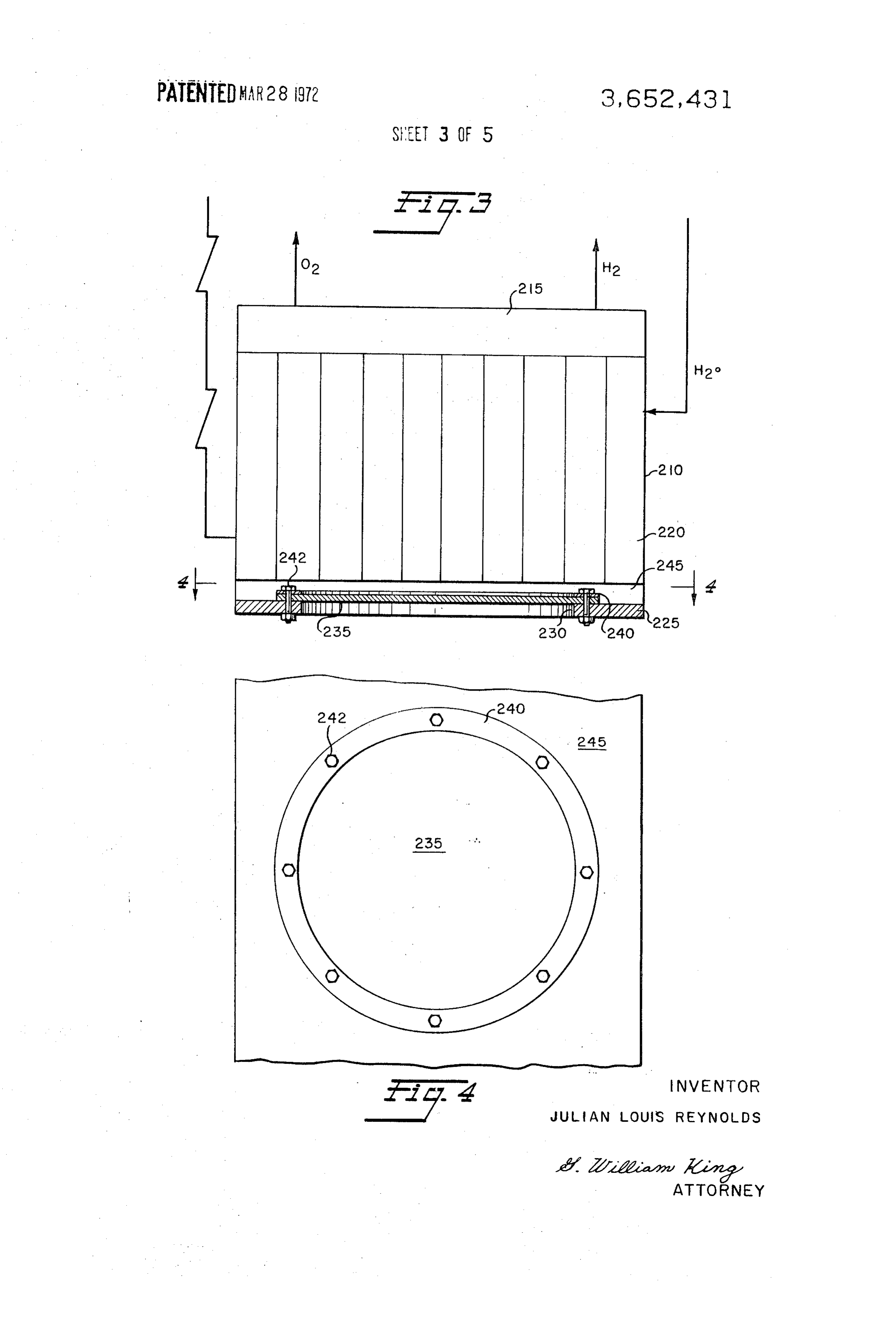
preferably located on shore with heavily insulated conductors through control valve 166. The oxygen ascends in the oxygen provided for carrying the low voltage, high amperage current separator iG3, through the drop separator 167, passes through to the submerged electrolyzer where they are connected by the line cooler 168 and finally through control valve 169 to pressure-tight and electrically insulated means similar to that consumption or surface storage. Instead of bringing the O, and employed on surface high pressure units. H to surface immediately underwater storage under pressures As shown, the electrolyzer is preferably supported from the approximately equal to that of the material leaving the separa ocean floor by a suitable platform. Other means of support tors may take place with the O or H, being introduced into an may be used, as for example, sunken barges, suspension from empty storage compartment similar in construction to the surface platforms and the like. pressure equalizing unit of FIG. 1, for example. Due to the Water is supplied directly to the electrolyzer from the am 10 temperatures and pressures involved, hydrogen and oxygen monia plant which under certain process arrangements can be isotopes may exist and these can be separated and removed a byproduct in the nitrogen production phase thereof. Since before using the O, and H liquids or gas. From gas separators the electrolyzer will operate continuously and under pressure, 162 and 163 the electrolyte passes to recycle pump 170, the water pressure must be increased enough above its own 15 which returns the electrolyte through filter 171 back to the hydrostatic pressure to enter the electrolyzer. After the elec cells, through pressure equalizer 172. trolyzer is initially charged with electrolyte, only slight adjust The interior pressure of the electrolyzor is maintained at the ment of the chemical make-up is normally periodically ambient water pressure by equalizer 172 having an open side required, and this may be conveniently done through the con 172A and impervious diaphragm 172B which is in contact necting line used to transmit feed water to the electrolyzer. 20 with the electrolyte in the line from pump 171 and filter 172. In the particular illustration used to depict the invention in Diaphragm 172B is preferably rubber one-half inches thick FIG. 2, the high pressure hydrogen and oxygen are conducted held in a sealed manner within the chamber by any suitable through piping back to the shore for use in ammonia synthesis means. Chamber 172C formed by diaphragm 172B and the in a known manner, or stored under pressure in either the closed end cylindrical wall of equalizer 172 is approximately liquid or gaseous state at any suitable depth desired in a 25 one-tenth to one-half the size of the electrolyzer containment storage tank, suspended from surface apparatus, or otherwise vessel with which it is associated, in this case vessel 181. The suitably stored below the surface, or in any event preferably pressure equalizer is mainly concerned with maintaining a under super-atmospheric pressure conditions. The same is more or less constant pressure in the containment vessel cor true of the synthetic ammonia produced. The latter novel con responding to its exterior superatmospheric environment. cept of handling ammonia, may be employed to eliminate the 30 Forced circulation of the electrolyte provides for intimate need for pressurized or refrigerated surface storage. mixing of anolyte and catholyte, so that discrepancies in the In this embodiment of the invention, the bottom wall 225 of concentration of the electrolyte in the anode and cathode container 220 is provided with means for equalizing the inter compartments of the cells are eliminated. This also ensures nal and external pressures of the electrolyzer. Thus wall 225 that all cells are uniformly supplied with an adequate quantity has an opening 230 formed therein over which a flexible 35 of electrolyte. The electrolyte filter provides continuous pu diaphragm 235 is positioned (preferably 4 inch rubber). The rification of the circulating electrolyte. The filter is equipped diaphragm, which may be of any shape desired, (shown in this with a number of perforated filter tubes which are fitted into a embodiment as a circular member) is fixed over the opening perforated tray and covered with dense filter cloth. The liquid by a sealing ring 240 and bolts 242, adapted to tightly seal the passes through the filter cloth and the perforated tray and edge of diaphragm 235 to the inner side 245 of wall 225. The 40 finally through a filter cylinder which is an additional diaphragm is preferably made from rubber, although plastics safeguard to prevent the ingress of impurities into the cells. and metals capable of withstanding chemical attack from both Internal pressure relief in the event of excessive working internal and external media, being flexible enough to respond pressure in the electrolysis unit is effected by pneumatic pres to pressure differentials between the interior and exterior in sure controller 173 which operates diaphragm valve 166 in excess of 4 p.s. i. for example, and capable of providing an ef 45 stalled in the hydrogen line. The controller is a pressure sensor fective seal with wall 225 when tightly secured thereto. which operates to open the hydrogen line in the event a In operation, the vessel 220 will be filled with electrolyte predetermined excessive pressure is reached within the unit. and gases and due to the flexibility of diaphragm 235, the pres The electrolyte level in the gas separators is kept constant by sure inside the electrolyzer will be substantially the same as 50 level controller 174 which controls the electrolyte level in ox the hydrostatic pressure of the sea. The operating pressure ygen separator 163. This controller operates diaphragm valve may, therefore, be selected to correspond with a particular 169 which opens or closes as a function of the level in the ox depth, or vice versa. The flexible diaphragm need not be capa ygen separator. Since both separating drums 162 and 163 are ble of equalizing the internal and external pressures exactly, connected by a number of communicating pipe bends 175 but should tend to accomplish this, and thereby create the 55 below the liquid surface, the maintenance of a constant level desired super-atmospheric condition desired internally. in the oxygen separator also keeps the level in the hydrogen Various means may be employed to install the above provided with a pressure relief valve which opens in the event described apparatus on the ocean floor, including, but not the pressure rises above the safe working pressure of equalizer limited to, mechanically pressurizing the electrolyzer interior chamber 172 and also limits the pressure. to approximate the exterior pressure as it is gradually lowered 60 Provisions are also provided to prevent the ingress of into place, to the extent necessary to prevent excess internal hydrogen from separator 162 into the oxygen compartment of or external stresses from developing during installation. separator 163. This is effected by the control of the electrolyte Another method is to fill the electrolyzer with a relatively in level in the separators. If the level in one separator drops as a compressible liquid, electrolyte for example, to prevent col result of a failure, for instance, of the level controller, electri lapse. 65 cal switch 178 is operated and disconnects the DC current As another example of a system utilizing the principles of supply. This eliminates further level variations because no this invention reference is made to FIGS. 5 and 6. more gas is produced. The isolating switch also operates an The mixtures of electrolyte and hydrogen and electrolyte audible and visible alarm. Direct-acting float valve 179, is pro and oxygen leave the cell blocks through ducts 159-H and vided as an additional protection, and opens the separator in 159-O respectively, pass through bends 160, and intermediary 70 which the electrolyte level has dropped as a result of the coolers 161 and then enter gas separators 162 and 163, where failure thus allowing the gas to escape. This causes a slight the gases are separated from the circulating electrolyte. The pressure drop in that separator whereby the levels in the two hydrogen ascends in the hydrogen separator 162, passes separators come into balance again.
through drop separator 164 to separate entrained electrolyte The foregoing description has been made in connection droplets, passes through the line cooler 165 and finally leaves 75 with apparatus adapted to be employed in the ocean. Any
Page 11
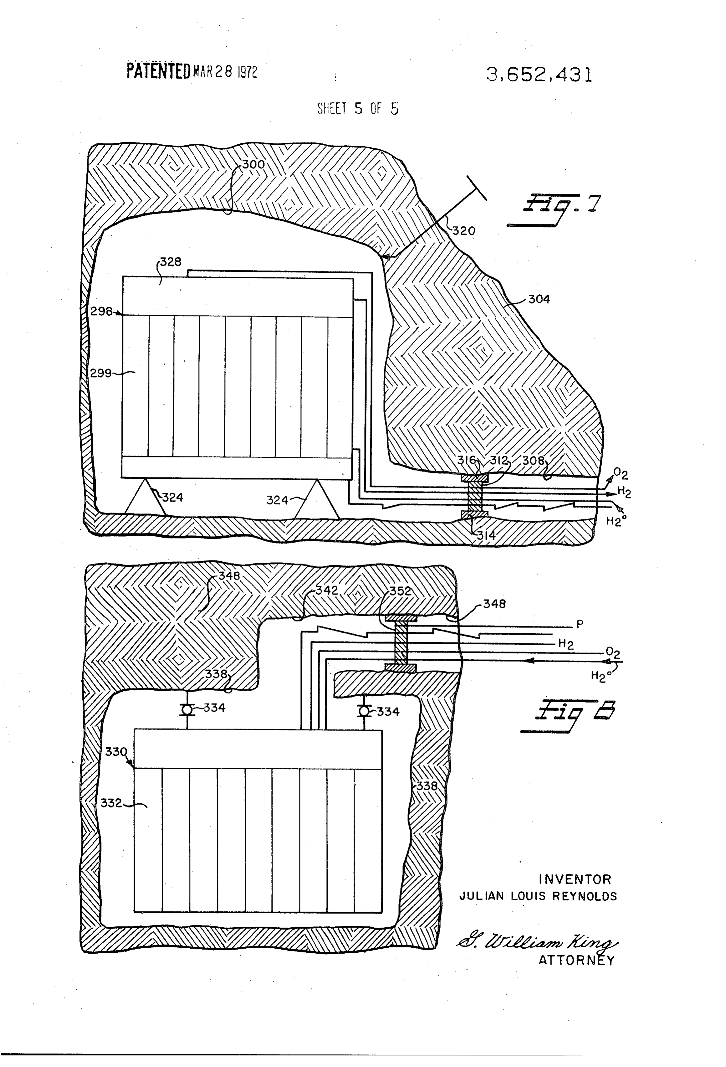
9 () body of water of adequate depth may be used, however. The therethrough. Closure 352 which is essentially the same as clo oceanic environment has several advantages in that it is freely sure 312 in FIG. 7, is located in passage 342. A conduit P is in available, great depths may be easily found if desired, and for dicated passing through closure 312 and passage 348 and is a given depth, a given pressure environment exists and will adapted to provide pressurized liquid or materials suitable for remain constant. Nevertheless, the present invention may util pressurizing cavity 338 in accordance with any of the methods ize other geological features, as for example, a mined or above-mentioned in connection with FIG. 7.
drilled land cavity, or a cavity which has formed from erosion, Where suitable geological formations such as formations volcanic activity, or any other cause. 304 and 348 are not available for creating a high pressure FIG. 7 illustrates another embodiment of this invention chamber, a cavity may be drilled into the earth, with a rotary wherein an electrolyzer 298 with cell 299 is assembled or 10 drilling technique. The bore hole may be enlarged at its lower otherwise positioned in a cavity 300 in a rock formation 304, extremity by washing, for example, as in salt dome formations which is preferably of a relatively impermeable nature. The or by explosion techniques known in the petroleum industry cavity may be lined with plastic or ductile metal or otherwise and under the A.E.C's "Plowshare Program.' Bore holes on rendered impermeable if this is a problem however. The cavity the order of 48 inches in diameter may presently be conven is provided with an entrance passage 308 having a closure 312 15 tionally drilled and even larger holes may be created by spel anchored and sealed at 314 and 316 against the inner wall of cial techniques to permit the original equipment to be lowered passage 308. The closure and interior of the cavity form a into the cavity, assembled and operated.
pressure vessel which may be pressurized by introducing a Still another available cavity would be an abandoned mine second medium through passage 320. The pressurizing medi in which vertical and horizontal shafts are available for the en um may be pumped through passage 320 or passage 320 may 20 trance of men and machinery.
be a standpipe bored through strata overlying formation 304 The invention may be embodied in other specific forms to create a static head when filled with the pressurizing medi without departing from the spirit or essential characteristics um. If higher pressures are desired, the specific gravity of the thereof. The present embodiments are therefore to be con medium may be increased. For example, by dissolving into a sidered in all respects as illustrative and not restrictive, the liquid or mechanically dispersing some additives such as 25 scope of the invention being indicated by the appended claims Barogel or other barite material, a greater static head and con rather than by the foregoing description, and all changes sequently a higher pressure may be achieved in cavity 300. which come within the meaning and range of equivalency of As shown, electrolyzer 298 is comprised of essentially the the claims are therefore intended to be embraced therein. same elements as the electrolyzers illustrated above and is What is claimed and desired to be secured by United States held in position by insulated supports 324. As illustrated, ox 30 Letters Patentis:
1. A method of carrying out an electrolytic process for ygen and hydrogen conduits are connected with the gas col lecting zone 328, and run through closure 312 and passage producing gases in an electrolyzer comprising at least one 308 to storage or consumption as desired. Water and electrici electrolytic cell and a containment vessel therefor, said ty are supplied through suitable conduits which also run method comprising supplying electric power to said elec through passage 308 and closure 312 to the electrolyzer. All 35 trolyzer from an external source during operation thereof, of these conduits are run through sealed openings in closure static subjecting said vessel to an external superatmospheric hydro 312 and are adapted to be disconnected when it is desired to electrolyte pressure, continuously charging said electrolyzer with open closure 312, for example, in the event of shutdown and trolyzer regulating under pressure and while operating said elec repair of the electrolyzer. the internal operating pressure of the con In addition to pressurizing cavity 300 by introduction of a 40 tinuous electrolytic system by collecting the produced gases liquid, other methods of obtaining pressure may be achieved. external to said electrolyzer and exerting external hydrostatic Mechanical compression of a liquid has already been men pressure against said collected gases generated and being in tioned. The cavity may also be filled with liquid or suitable gas fluid communication with the interior of said electrolyzer so and heat or heat generating materials, introduced to expand that said internal and external pressures are approximately the and create pressure or material may be introduced into the 45 same during said operating.
cavity and thermally and electrolytically decomposed to in 2. A method as defined in claim wherein said electrolyzer crease pressure. Electrolysis of water is one example. Still is located below the surface of a body of water during opera another method is to introduce materials into cavity 300 and tion, and said gases are separately collected in compartments cause them to react chemically and expand to increase pres and subjected to pressure approximately equal to said internal Ste. 50 operating pressure of said electrolyzer. In FIG. 8, another arrangement of the system shown in FIG. 3. A method as defined in claim 2 wherein said electrolyte is 7 is represented. In this particular arrangement, the elec water, said gases generated are hydrogen and oxygen, and the trolyzer 330 with cells 332 which is essentially the same as that latter are transmitted in free flowing conduits from said elec described above in connection with FIG. 7, is supported by in trolyzer to separate compartments located at approximately the same depth as said electrolyzer and open in the lower por sulated supports 334 from the roof of cavity 338. A passage 55 tion thereof whereby said gases are pressurized at substantially 342, through formation 348 to cavity 338, is provided for ini tially installing the electrolyzer and subsequently passing the the same pressure as that of said body of water. hydrogen, oxygen, direct current and water conduits k .. x x .
Provenance
- Collection
- Cited prior art
- Original PDF
- patentimages.storage.googleapis.com →
- Filed
- 1970-03-12
- Pages
- 11
- Method
- pdftotext (the PDF's own text layer) + pdftoppm 300dpi page scans
- Source
- Google Patents bibliographic record
- Granted
- 1972-03-28
- Inventors
- Julian Louis Reynolds
- Transcribed from
- patentimages.storage.googleapis.com →