patent · US11492938B2
Carbon capture in an internal combustion engine
8 November 2022
Page 1 — bibliographic record
( 12 ) Beckman
United States Patent ( 10 ) Patent No.: US 11,492,938 B2
( 54 ) CARBON CAPTURE IN AN INTERNAL ( 58 ) Field of Classification Search COMBUSTION ENGINE CPC FO2M 21/0206 ; FO2D 19/0644 See application file for complete search history .
( 71 ) Applicant: Applied Resonance Technology LLC , ( 56 ) References Cited Ham Lake, MN (US )
( 72 ) Inventor : Michael Beckman , Ham Lake , MN
(US ) 4,141,326 A * 2/1979 Wolber FO2B 43/10
( 73 ) Assignee : APPLIED RESONANCE 4,255,789 A 3/1981 Hartford et al. TECHNOLOGY LLC , Ham Lake, 4,411,223 A 10/1983 Kiely
MN ( US ) 4,513,728 A 4/1985 Ullman et al .
( * ) Notice: Subject to any disclaimer, the term of this (Continued ) patent is extended or adjusted under 35
U.S.C. 154 (b ) by 0 days. FOREIGN PATENT DOCUMENTS ( 21 ) Appl. No .: 17/188,352 JP 2002013447 A 1/2002 FOIN 3/0857 ( 22 ) Filed : Mar. 1 , 2021 OTHER PUBLICATIONS ( 65 ) Prior Publication Data English Translation of JP2002013447A ( Year: 2002 ) . * US 2021/0270159 A1 Sep. 2 , 2021 Primary Examiner — Anthony Ayala Delgado (74 ) Attorney , Agent, or Firm — Larkin Hoffman Daly &
Related U.S. Application Data Lindgren, LTD .
( 60 ) Provisional application No. 62/ 983,185 , filed on Feb. ( 57 ) ABSTRACT 28 , 2020 . An automobile includes an internal combustion engine hav (51 ) Int. Ci. ing an emission control system , intake manifold and an FOIN 3/021 ( 2006.01) exhaust manifold. A hydrogen source is positioned to deliver FO2M 35/10 ( 2006.01 ) hydrogen to the intake manifold . Hydrogen and gasoline FOIN 1/02 ( 2006.01 ) combustion takes place in a cylinder of the internal com FO2M 21/02 ( 2006.01 ) bustion engine and a catch device is positioned to receive fluid mixture from the exhaust manifold of the internal
FOIN 3/28 ( 2006.01 ) combustion engine. The catch device condenses the fluid
( 52 ) U.S. CI . mixture and a filter receives the condensed fluid mixture from the catch device and filters the condensed fluid mix
CPC FOIN 3/021 ( 2013.01 ) ; FOIN 1/02 ture . A container is positioned to receive the filtered fluid (2013.01 ) ; FOIN 3/28 (2013.01 ) ; FOIN 13/10 mixture .
35/10216 ( 2013.01 ) 16 Claims , 3 Drawing Sheets
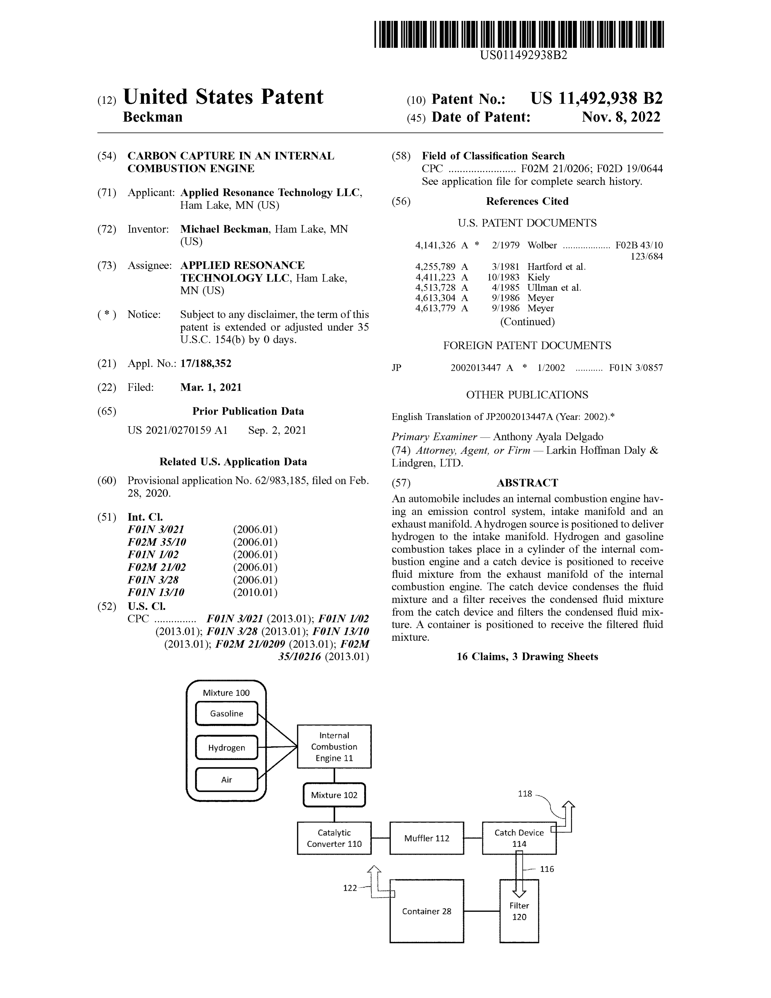
Mixture 100
Gasoline
200 Hydrogen
Air
Internal
Combustion
Engine 11
Mixture 102
Catalytic
Catch Device
Filter
Container 28
Page 2
( 56 ) References Cited 11,118,490 B2 * 9/2021 Coldren FOIN 3/0205
4,798,661 A 1/1989 Meyer 123/3 4,826,581 A 5/1989 Meyer 2007/0277775 A1 * 12/2007 Orlosky FO2M 25/14 4,936,961 A 6/1990 Meyer 123/25 C 5,149,407 A 9/1992 Meyer 2008/0092831 A1 4/2008 Simon 6,226,981 B1 5/2001 Bruch et al. 2008/0282612 A1 * 11/2008 De Bas F25J 3/067 6,253,751 B1 7/2001 Carlsson 48 / 127.7 6,332,434 B1 12/2001 De et al . 2009/0194042 A1 * 8/2009 Workman FO2M 25/0228 6,581,375 B2 * 6/2003 Jagtoyen FOIN 3/043 123/3 60/309 2009/0235902 A1 * 9/2009 Coffey B6OK 15/10 6,651,623 B1 11/2003 Tang et al. 123/536
7,597,091 B2 10/2009 Suzuki et al. 2012/0167461 A1 * 7/2012 Bentzen CIOK 1/06 7,765,794 B2 * 8/2010 Alexander E21B 43/168 48/61 60/285 2013/0333638 A1 * 12/2013 Nishida FO2B 43/00 7,899,606 B2 3/2011 Bartick 123/3 8,336,508 B2 12/2012 Huttner 2015/0198108 Al 7/2015 Mullen 8,852,410 B1 10/2014 Turgeon et al . 2017/0114756 A1 * 4/2017 McAlister FO2M 27/04 8,959,988 B2 2/2015 Inagaki et al . 2018/0195469 A1 * 7/2018 Hamad FO2M 26/35 8,961,761 B2 2/2015 Maeda 2018/0219267 A1 * 8/2018 Martin HO1M 8/04858 9,051,872 B2 6/2015 Monros 2019/0209961 A1 * 7/2019 Kennedy BO1J 20/3483 9,771,658 B2 9/2017 Haring 2020/0400058 A1 * 12/2020 Fujihara BOOK 6/24
10,648,379 B2 * 5/2020 Na B60L 50/72 * cited by examiner
Page 3
Drawing sheet — no readable text.
Page 4
Drawing sheet — no readable text.
Page 5
Drawing sheet — no readable text.
Page 6
CARBON CAPTURE IN AN INTERNAL charges negative ions and regulates the impurity of distilled COMBUSTION ENGINE water that is forced to the electrolysis water cell 19 to control amperage .
BACKGROUND
During operation, power from the battery 16 is provided to the water cell 19 , where water within tank 19 is split into
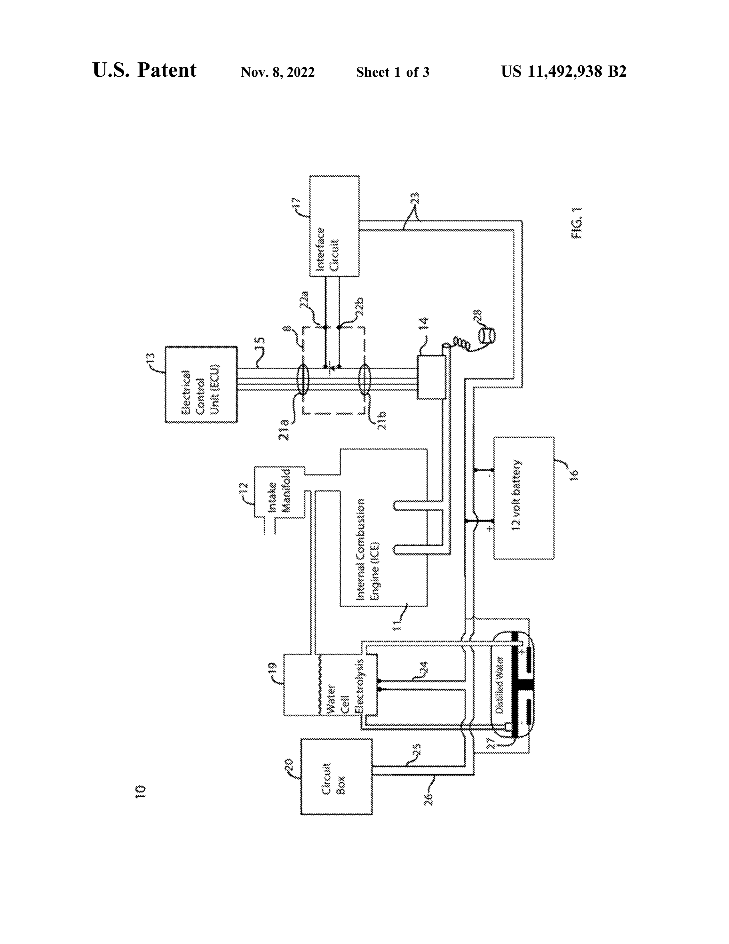
Adding hydrogen to gasoline in an internal combustion hydrogen and oxygen . Hydrogen is then provided into the engine includes : splitting water, producing a hydrogen and intake manifold 12 and mixed with ambient air. The fuel oxygen mixture , combining the mixture with ambient air in (e.g. , gasoline ) is also injected into the ambient air -hydrogen the intake manifold, injecting fossil fuel into the cylinder , 10 mixture in the ICE 11. The ICE 11 ignites the mixture to compressing it with a piston , and igniting the mixture. As a produce power through combustion . Subsequent to the ICE result , in current hydrogen systems, there is less hydrocar- 11 , gases and water mixture are exhausted from the ICE 11 bon reaction in the exhaust compared with a gasoline - only as will be discussed below. A cooling coil and capture conventional internal combustion engine . By utilizing container 28 can be provided to capture water from the hydrogen in combination with an internal combustion 15 exhaust of the ICE 11 .
engine, emission from fossil fuel ignition can be reduced . In a conventional automobile, the oxygen sensor 14 sends a signal to the ECU 13. Dependent upon the signal from the
SUMMARY oxygen sensor 14 , the ECU 13 will protect various valves and other elements (e.g. , a catalytic converter ) associated
An automobile includes an internal combustion engine 20 with the ICE 11 by modifying operation of the ICE 11. When having an intake manifold and an exhaust manifold . A hydrogen is further supplied to the intake manifold 12 , the hydrogen source is positioned to deliver hydrogen to the oxygen sensor 14 produces a signal indicative of low levels intake manifold of the internal combustion engine and a of hydrocarbons in the exhaust of the ICE 11. As a result, the catch device is positioned to receive fluid mixture from the ECU 13 will adjust operation of the ICE 11 to increase exhaust manifold of the internal combustion engine. The 25 enrichment of the fuel .
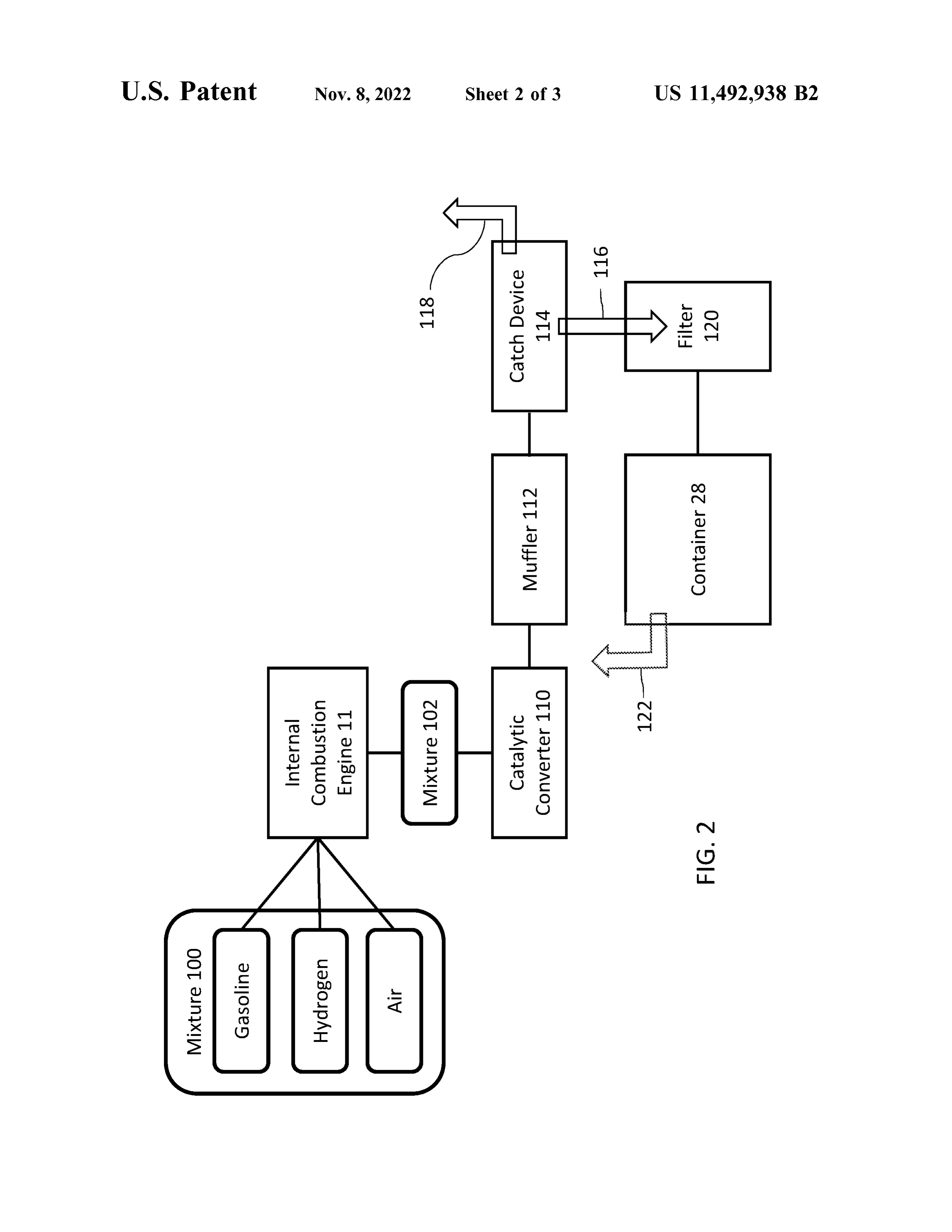
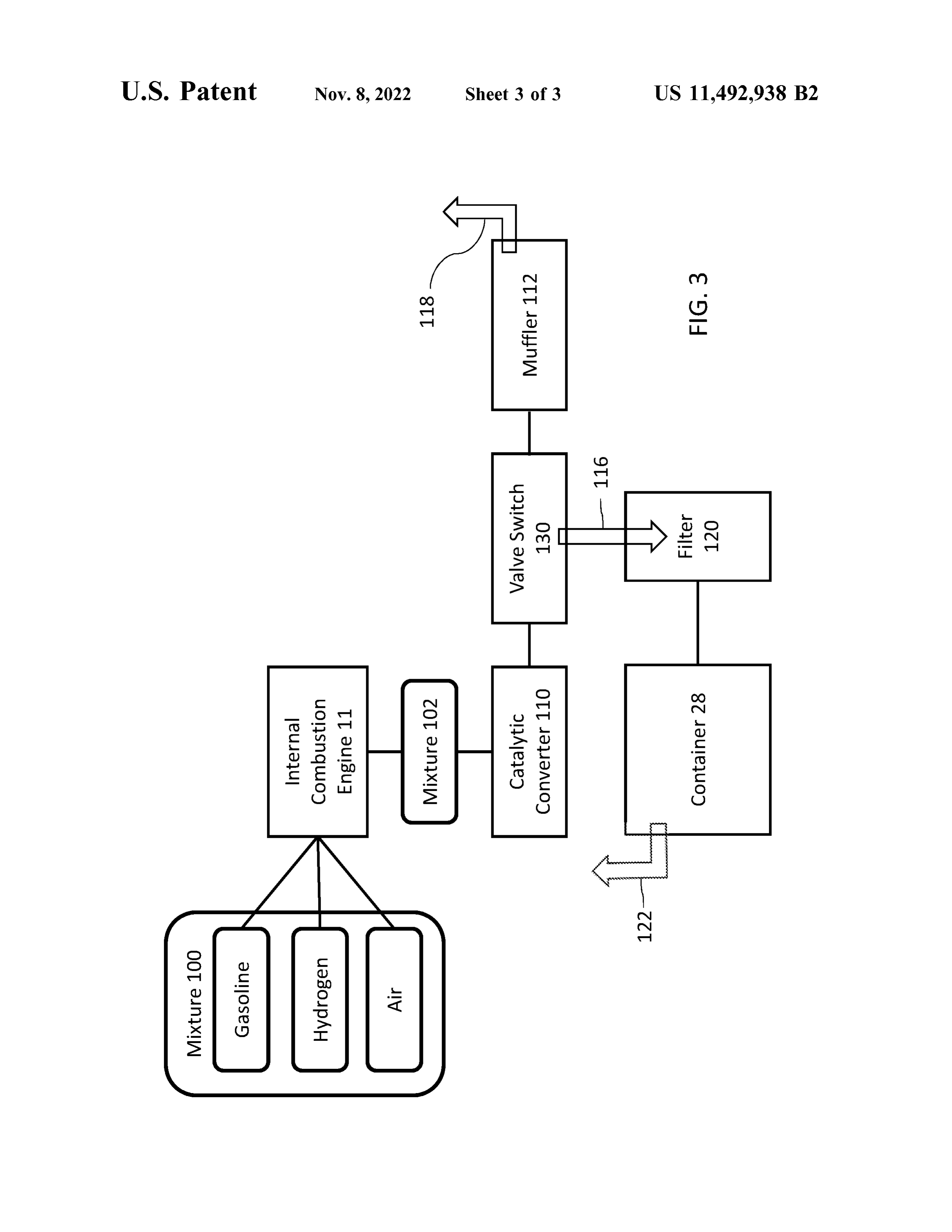
catch device condenses the fluid mixture and a filter receives FIG . 2 is a schematic flow diagram of fluids flowing the condensed fluid mixture from the catch device and filters through automobile 10 according to one embodiment. As the condensed fluid mixture . A container is positioned to discussed above with respect to FIG . 1 , a mixture 100 of receive the filtered fluid mixture . gasoline , hydrogen and ambient air are provided to ICE 11 30 (i.e. , through the intake manifold ). Mixture 100 is ignited
BRIEF DESCRIPTION OF THE DRAWINGS within cylinders of the ICE 11 , producing a mixture 102 of oxygen and water, which is sent to an exhaust manifold of
FIG . 1 is a schematic block diagram of an automobile . the ICE 11. Water produced from the ignited mixture FIG . 2 is a schematic flow diagram of carbon capture in includes carbon and nitrogen suspended in the water. In water released from an internal combustion engine . 35 particular, mixture 100 within the ICE 11 creates a plasmatic FIG . 3 is a schematic flow diagram of carbon capture in explosion
Water that cracks hydrocarbon bonds in the gasoline .
dissolves carbon, nitrogen and other molecules from steam released from an internal combustion engine. the mixture 100. The mixture 102 pass through a catalytic DETAILED DESCRIPTION convertor 110 and muffler 112 to a catch device 114. The 40 catch device 114 can be formed of a material that exhibits
FIG . 1 is a schematic diagram of components of an high thermal conductivity, such as copper, carbon steel , stainless steel , nickel alloys and titanium . In one embodi automobile 10 , including an internal combustion engine ment ( ICE ) 11 having an intake manifold 12. An electrical control tank ,formed the catch device can be a conventional automobile fuel of metal ( e.g. , steel , aluminum ) or plastic ( e.g. , unit ( ECU ) 13 is operatively coupled with the ICE 11 in 45 high density polyethylene ). The catch device 114 condenses order to control air to fuel ratio of the mixture provided to the water in mixture 102 and can transmit the condensed the ICE 11 based on signals from an oxygen sensor 14. The water from mixture 102 through a coil 116. Additionally, any ECU 13 and oxygen sensor 14 are communicatively coupled gas released from the mixture 102 (e.g. , oxygen ) can exit the through a wire harness 15 . catch device 114 through an outlet 118 such as a conven A battery 16 is coupled with an interface circuit 17 to 50 tional tail pipe .
transform signals from the oxygen sensor 14 to the ECU Water from coil 116 is passed through a filter 120 , such as when hydrogen is being provided to the ICE 11. The a carbon activated filter that operates to remove impurities interface circuit 17 is coupled to the wire harness 5 through from the condensed water. Other example filters can scrub a connection assembly 8 (e.g. , a pair of pigtail connections contaminants from the water and include membranes and 21a and 21b) in order to provide increased mil -voltages to 55 other devices to filter the condensed water. In one embodi signals from the oxygen sensor 14 when an electrolysis cell ment, the filter is a conventional carbon house water filter 19 provides hydrogen to the ICE 11. The interface circuit 17 that includes a carbon block to filter contaminants from the is connected with an input port 22a and an output port 22b water such as carbon, nitrogen and oil residue . From filter of the interface circuit 17. The water cell 19 can be con- 120 , water can be transmitted to container 28. In one trolled with a suitable circuit box 20. Wires 23 connect the 60 embodiment, the container 28 includes a vent 122 open to battery with the interface circuit 17 . release oxygen gas from container 28 . A wire 24 connects the battery 16 with the electrolysis In an alternative embodiment, illustrated in FIG . 3 , a catch water cell 19 and a wire 25 connects the electrolysis cell device in the form of a valve switch 130 is positioned with the circuit box 20. A further wire 26 connects the circuit between the catalytic converter 110 and the muffler 112. In box 20 with the battery 16. The water cell 19 contains water 65 one embodiment, valve switch 130 can be a 12 - volt electric that will be converted to hydrogen and oxygen by electroly- solenoid valve switch . Cooling coil 116 is connected to the sis . The water cell 19 further includes a water tank 27 that valve switch 130 and directs water to the filter 120. Water
Page 7
that is filtered by filter 120 is sent to container 28 , with 5. The automobile of claim 1 , further comprising coil
excess gas being released through muffler 112 and tailpipe tubing fluidly coupling the catch device to the filter. 118 . 6. The automobile of claim 1 , wherein the catch device Various embodiments of the invention have been valve switch .
described above for purposes of illustrating the details 5 7. The automobile of claim 1 , wherein the catch device is thereof and to enable one of ordinary skill in the art to make formed of one of copper, carbon steel , stainless steel , nickel and use the invention . The details and features of the alloys and titanium .
disclosed embodiment[ s] are not intended to be limiting , as 8. The automobile of claim 1 , wherein the catch device is many variations and modifications will be readily apparent formed of metal or plastic . to those of skill in the art. Accordingly, the scope of the 10 9. A method present disclosure is intended to be interpreted broadly and comprising: of operating an internal combustion engine, to include all variations and modifications coming within the producing hydrogen using an electrolysis cell ; scope and spirit of the appended claims and their legal delivering hydrogen to an intake manifold of the internal equivalents .
The invention claimed is : 15 combustion engine ;
1. An automobile, comprising: using an interface circuit to provide a signal to the internal an internal combustion engine including an intake mani combustion engine indicative of hydrogen being pro fold and an exhaust manifold ; vided to the internal combustion engine; an electrolysis cell including a water tank to produce delivering gasoline to the internal combustion engine ; hydrogen and positioned to deliver hydrogen to the 20 igniting the hydrogen and gasoline to produce a fluid intake manifold of the internal combustion engine; mixture to an exhaust manifold ; an interface circuit connected with the internal combus- condensing fluid mixture from the exhaust manifold of the tion engine and providing a sigal to the internal com internal combustion engine;
bustion engine indicative of the electrolysis cell deliv- filtering the condensed fluid mixture; and ering hydrogen to the intake manifold ; 25 storing the filtered fluid mixture . a gasoline source positioned to deliver gasoline to the 10. The method of claim 9 , wherein filtering includes intake manifold of the internal combustion engine, using a carbon activated filter.
wherein the internal combustion engine ignites the 11. The method of claim 9 , wherein condensing includes hydrogen and gasoline to produce aa fluid mixture to the positioning a catch device to receive the fluid mixture from exhaust manifold ; 30 a catalytic converter that is fluidly coupled with the exhaust a catch device positioned to receive the fluid mixture from manifold of the internal combustion engine. the exhaust manifold of the internal combustion engine 12. The method of claim 11 , further comprising fluidly and condense the fluid mixture;
a filter positioned to receive the condensed fluid mixture coupling a muffler with the catalytic converter and deliver from the catch device and filter the condensed fluid 35 device ing the. fluid mixture from the catalytic converter to the catch mixture ; and 13. The method of claim 11 , further comprising fluidly a container positioned to receive the filtered fluid mixture. coupling coil tubing to the catch device . 2. The automobile of claim 1 , wherein the filter is aa carbon activated filter. 14. The method of claim 9 , wherein condensing the fluid 3. The automobile of claim 1 , further comprising a 40 mixture includes capturing steam from the exhaust manifold catalytic converter fluidly coupled with the exhaust manifold with15.anTheelectric method valve switch .
of claim 11 , wherein the catch device is of the internal combustion engine and configured to deliver formed of one of copper , carbon steel , stainless steel , nickel the fluid mixture to the catch device .
4. The automobile of claim 3 , further comprising a muffler alloys and titanium .
16. The method of claim 11 , wherein the catch device is fluidly coupled with the catalytic converter and configured 45 formed of metal or plastic .
to deliver the fluid mixture from the catalytic converter to the catch device .
Provenance
- Collection
- Patents citing this work
- Original assignee
- Applied Resonance Technology LLC
- Pages
- 7
- Method
- pdftotext (the PDF's own text layer) + pdftoppm 300dpi page scans
- Patent office record
- patents.google.com →
- Source
- Google Patents citing-documents table
- Inventors
- Michael Beckman; Applied Resonance Technology LLC
- Published
- 2022-11-08
- Transcribed from
- patentimages.storage.googleapis.com →