patent · US4008709
Underground storage system for heating and cooling systems
22 February 1977
Page 1 — bibliographic record
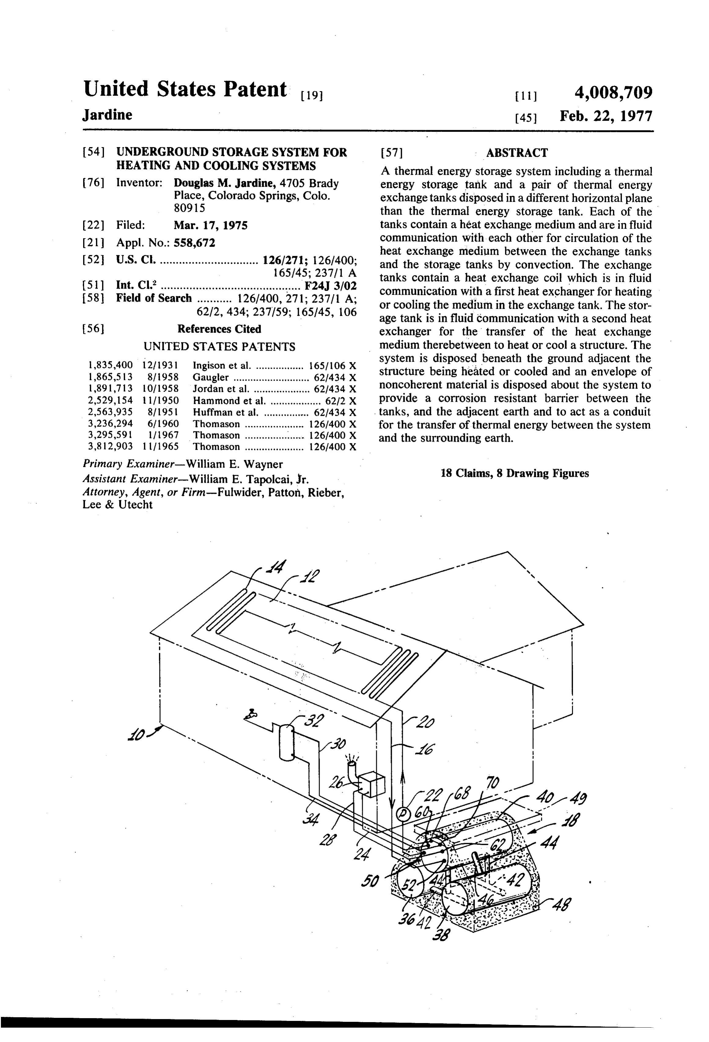
United States Patent to 1 l) 4,008,709 Jardine 45 Feb. 22, 1977 54) UNDERGROUND STORAGESYSTEM FOR 57 ABSTRACT HEATING AND COOLING SYSTEMS A thermal energy storage system including a thermal 76) Inventor: Douglas M. Jardine, 4705 Brady energy storage tank and a pair of thermal energy Place, Colorado Springs, Colo. exchange tanks disposed in a different horizontal plane 80915 than the thermal energy storage tank. Each of the 22 Filed: Mar. 17, 1975 tanks contain a heat exchange medium and are in fluid 21 Appl. No.: 558,672 communication with each other for circulation of the heat exchange medium between the exchange tanks 52 U.S. C. ............................... 126/271; 126/400; and the storage tanks by convection. The exchange 165/45; 237/1 A tanks contain a heat exchange coil which is in fluid 5ll Int. Cl.’............................................ F24J 3/02 communication with a first heat exchanger for heating 58 Field of Search ........... 126/400, 271; 237/1 A; or cooling the medium in the exchange tank. The stor 62/2, 434; 237/59; 165/45, 106 age tank is in fluid communication with a second heat 56 References Cited exchanger for the transfer of the heat exchange UNITED STATES PATENTS medium therebetween to heat or cool a structure. The 1835,400 12/1931 Ingison et al. ................. 165/106 X system is disposed beneath the ground adjacent the 1,865,513 8/1958 Gaugler ........................... 62/434 X structure being heated or cooled and an envelope of l,891,713 l Of 1958 Jordan et al. ............. ... 621434 X noncoherent material is disposed about the system to 2,529, 154 l l l 1950 Hammond et al. .................. 6212 X provide a corrosion resistant barrier between the 2,563,935 8/1951 Huffman et al. ................ 62.1434 X tanks, and the adjacent earth and to act as a conduit 3,236,294 6/1960 Thomason ............ ... 126/400 X for the transfer of thermal energy between the system 3,295,591 111967 Thomason ..................... 126/400 X and the surrounding earth.
3,812,903 l l 1965 Thomason ..................... 126/400 X
Primary Examiner-William E. Wayner 18 Claims, 8 Drawing Figures Assistant Examiner-William E. Tapolcai, Jr.
Attorney, Agent, or Firm-Fulwider, Patton, Rieber,
Lee & Utecht
Page 2
Drawing sheet — no readable text.
Page 3
Drawing sheet — no readable text.
Page 4
tainers, and additionally provides for the effective
UNDERGROUND STORAGESYSTEM FOR transmission of thermal energy therebetween. In this HEATING AND COOLNG SYSTEMS manner, the earth acts as a storage area for thermal BACKGROUND OF THE INVENTION energy, which is retrieved when needed for heating the heat exchange medium and for receiving thermal en
This invention relates to heating and cooling systems ergy from the heat exchange medium to cool the heat and more, particularly to an improved system for the exchange medium, depending upon the mode of opera utilization of natural thermal energy sources for heat tion. The system is provided with heat exchange means ing and cooling structures and the like. in communication with a first external heat exchanger A variety of systems utilizing solar energy as a source O for gaining or losing thermal energy and with a second of thermal energy have been developed for various heat exchanger for imparting or removing thermal en purposes and with the increasing emphasis on the con ergy from a structure.
servation of hydrocarbon fuels, solar heating systems Preferably, the system comprises at least one fluid are becoming increasingly attractive for use in the storage tank and at least one exchanger tank disposed space heating of structures. Likewise, cooling systems 5 in different horizontal planes with respect to one an involving the atmospheric radiation of heatenergy for other and the tanks are in fluid communication with cooling fluids are known, although when utilized for each other. When in the heating mode, the exchanger structural cooling, the systems normally are employed tank is disposed in a horizontal plane below that of the with a heat pump which requires additional energy fluid storage tank. The exchange tank contains heat input for operation. Because of the intermittent nature 20 exchange means in communication with the first heat of solar heating and atmospheric radiation to effect exchanger and as the heat exchange medium gains in heating and cooling, an effective thermal energy stor thermal energy it flows upwardly to the fluid storage age system is required for the containment of thermal tank for storage therein and flows back to the ex renergy as conditions permit. changer tank as it loses thermal energy. The fluid stor Most thermal energy storage systems, particularly 25 age tank includes the heat exchange means in commu where solar derived thermal energy is concerned, in nication with the second heat exchanger for transmittal volve the storage of sensible heat in large tanks of water of thermal energy to the structure. or in rock bins. However, with such systems, the stor In addition to the foregoing, thermal energy is also age capacity is limited by the volume of the storage radiated from the exchange medium to the earth system. Extremely large storage capacities are gener 30 through the walls of the containers and the envelope ally not economical. surrounding the containers. Earth stored thermal en Attempts to utilize the earth as a storage medium for ergy serves to heat the heat exchange medium in the thermal energy have been made but have proved defi containers at such a time as the temperature of the heat cient for several reasons. For example large reservoirs exchange medium falls below that of the earth and for containing hot water and the like are impractical for 35 thus, excess thermal energy is available for heating most installations due to the high cost of preparing the purposes at such times as when the input of thermal reseWO. energy from the first heat exchanger is insufficient to Likewise, systems involving burying lines in the earth supply the demand for heat at the second heat ex through which a heat exchange fluid is circulated have changer.
generally proved to be impractical because of the large 40 In the cooling mode, the position of the fluid storage number of lines required in order to effect the ex tank and the exchanger tank is reversed and the fluid change of a practical quantity of heat energy for use in storage tank is disposed in a horizontal plane below even a small structure such as a single family residence. that of the exchanger tank. Operation of the system is Another important deficiency in such systems is the the reverse of that described above, and the heat ex formation of an air film around the buried lines which 45 change medium containing the least amount of thermal results from compaction of the earth immediately sur energy is contained in the lower fluid storage tank. rounding the line due to the expansion and contraction Thermal energy is removed from the earth during pe of the line as the heat exchanger fluid loses thermal riods that the temperature of the heat exchange me energy to the earth. The air film in effect insulates the dium falls below that of the surrounding earth and the line and severely inhibits the efficient exchange of ther 50 earth subsequently functions as a cool storage area for mal energy. Corrosion of the lines is another serious the heat exchange medium in the containers. deficiency in such systems. The system of this invention, with its high storage The present invention overcomes the foregoing defi capacity, can be operated during periods when the ciencies in underground thermal energy storage sys demand for thermal energy is low to store excess quan tems and provides a highly efficient and economical 55 tities of thermal energy for use during peak periods. system for the storage of thermal energy in heating and Likewise, in the cooling mode, the system can be oper cooling systems. ated during non-demand periods to remove thermal SUMMARY OF THE INVENTION energy from the earth to create a cool zone around the containers which functions to receive thermal energy
The present invention resides in a thermal energy 60 from the heat exchange medium during the peak cool storage system particularly adapted for use in combina ing periods.
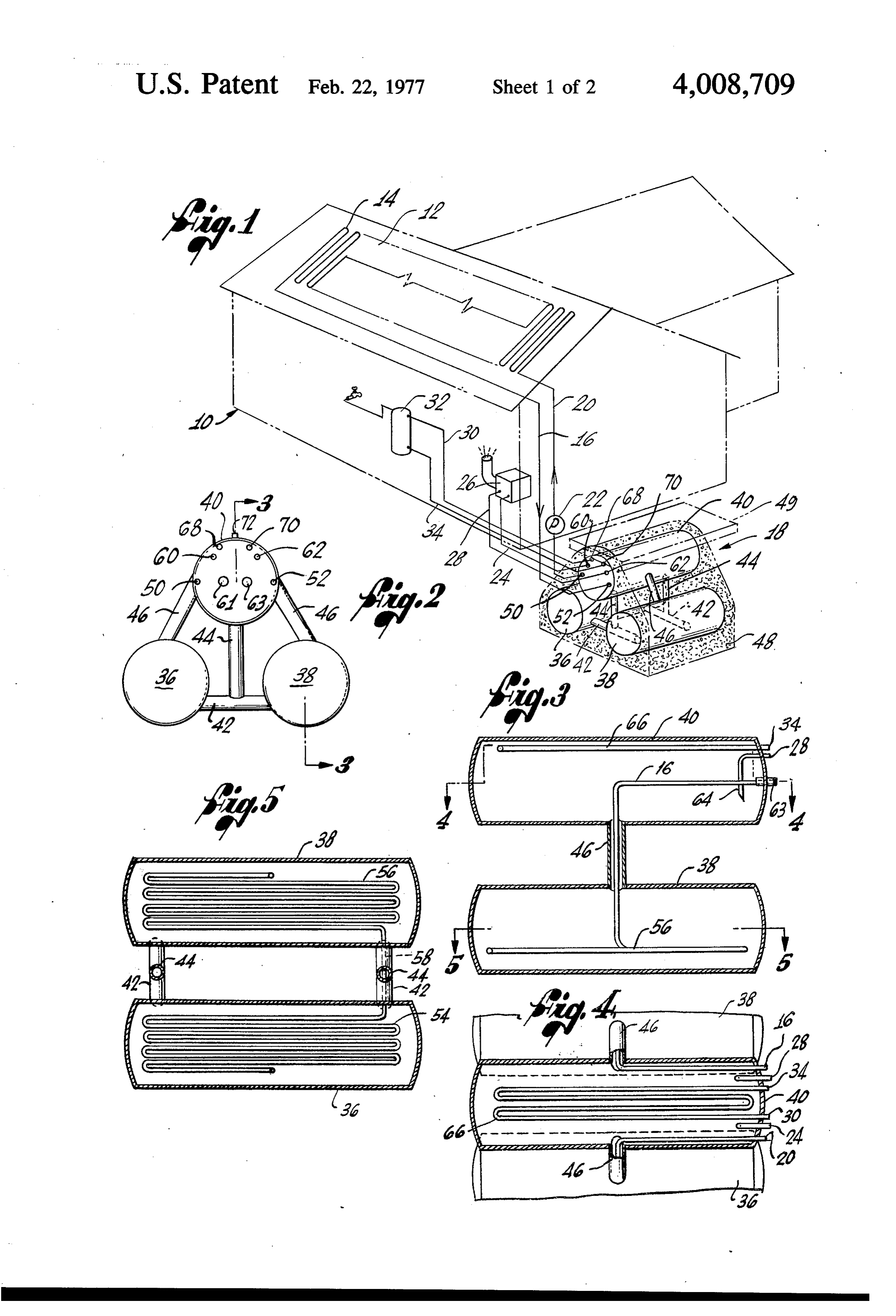
tion with structural space heating and cooling systems. These and other advantages of the present invention The system is disposed underground adjacent the struc will be apparent from the following detailed description ture or structures to be serviced and includes a plurality taken in connection with the drawings. of containers in which is contained a heat exchange 65 BRIEF DESCRIPTION OF THE DRAWINGS medium. An envelope of non-coherent particulate ma terial surrounds the containers and acts to prevent the FIG. 1 is a partially diagramatic partially isometric formation of air films between the earth and the con view showing a complete heating system incorporating
Page 5
the thermal energy storage system operating on the manner, for the storage of excess solar energy and for principles of the present invention; the recovery thereof when needed. FIG. 2 is an enlarged front elevation of the heat stor As is shown in FIGS. 1 and 2, in a preferred embodi age system illustrated in FIG. 1; ment of the invention, the heat storage system 18 com FIG. 3 is a sectional view taken through line 3-3 of 5 prises a pair of exchanger tanks, 36 and 38, which are FIG. 2; spaced apart and disposed in substantially the same FIG. 4 is a sectional view, partially broken away for plane and a hot fluid storage tank 40 disposed in a compactness of illustration, taken through line 4-4 of plane above the exchanger tanks. The exchanger tanks 36 and 38 are in fluid communication with each other
FIG. 5 is a sectional view, taken through line 5-5 of by means of lateral conduits 42 and are in communica
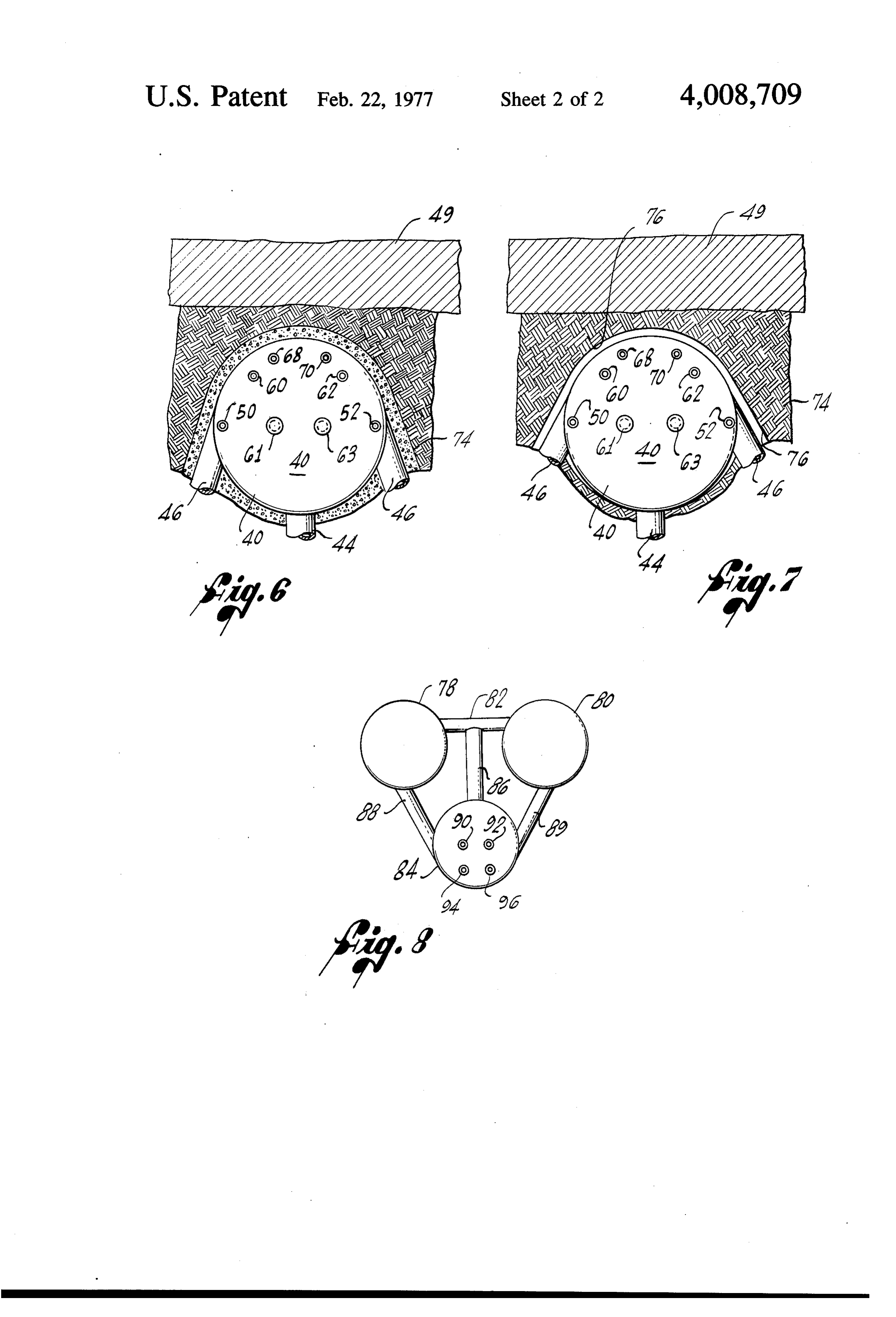
FIG. 3; tion with the hot fluid storage tank 40 by means of FIG. 6 is an enlarged front elevation with portions in downcomers 44 which communicate between the lat section and portions broken away for compactness of eral conduits and the hot fluid storage tank, and by means of risers 46 communicating between each of the illustration, illustrating a hot fluid storage tank dis 15 tanks 36 and 38 and the hot fluid storage tank 40. The posed in the earth and having an envelope of non heat storage system 18 is preferably disposed in an coherent material thereabout; underground location adjacent the structure 10 so that FIG. 7 is a view similar to FIG. 6 illustrating the effect energy of not having a surrounding envelope of non-coherent changerstored in the hot fluid tank 40 and the ex tanks 36 and 38 is conducted through the walls material; and
FIG. 8 is a front elevation of a heat storage system 20 of the tanks and retained in the surrounding earth for retrieval when the temperature of the tank falls below incorporating the principles of the present invention that of the surrounding earth. In this manner the stor and being disposed for cooling purposes. age capacity of the system 18 is substantially increased. DETAILED DESCRIPTION OF THE INVENTION The dimensions of the tanks 36, 38 and 40 can be 25 varied depending upon well understood determinants
As illustrated in FIGS. 1-7, the invention is embodied in a heating system wherein the heat source is solar such load, as for example the type of structure, the heating the type of heat exchange, and the like. The em derived. As is more specifically shown in FIG. 1, a bodiment structure 10 is provided with a rooftop heat exchange heating a illustrated in FIGS. 1 and 2 is designed for panel 12 suitably located for exposure to the rays of the 30 climate and the tanks 36,residence single family in a severe winter sun. The heat exchange panel 12 comprises heat ex 36 inches and a length of3820andfeet 40 have a diameter of change coils 14 which are formed of a suitable heat maximum heat exchange medium so as to provide a capacity of about conductive material for transmitting solar energy to 424 cubic feet.
heat exchange fluid contained therein. The heat ex The system 18 is disposed in the earth below the frost change coils 14 are preferably utilized in conjunction 35 line and preferably at a point where the ambient tem with solar collectors, not shown, of conventional design perature of the earth remains substantially constant. for focusing the rays of the sun on the coils. The spe cific arrangement and design of solar collectors and of The vary exact depth of the system 18 is not critical and will depending upon the local climatic conditions. It the heat exchange coils 14 for the heating of fluids has been found that a depth of on the order of 10 feet therein does not form a part of the present invention. 40 below the surface is adequate for most conditions en Heated fluid is led by line 16 to an underground heat countered in the United States. An envelope 48 of storage system shown generally at 18, and cooled heat particulate, non-coherent, non-corrosive material is exchange fluid is led back to the heat exchange panel disposed about the heat storage system 18, and be 12 through line 20 for reheating. A pump 22 in the line tween the tanks 36, 38 and 40, so as to provide a bar 20 provides the necessary pumping action for the circu 45 rier between the heat storage system and the surround lation of the heat exchange fluid between the heat ing earth. Preferably the envelope 48 has an apparent exchange panel 12 and the heat storage system 18. coefficient of thermal conductivity (k) in BTU/(hr) A line 24 leads from the heat storage system 18 to a (ft2) (LF) of at least that of the surrounding earth so as conventional heat exchanger, such as a heat pump, to not interfere with the energy transfer between the illustrated schematically at 26, for circulating heat SO heat storage system 18 and the earth. For the embodi exchange fluid from the storage system to the heat ment described herein, good results are achieved when pump for the removal of heat therefrom and for the the thickness of the envelope 48 between the heat distribution of the heat within the structure 10. storage system 18 and the earth ranges between about A line 28 provides return circulation to the heat 8 to about 24 inches. The thickness of the envelope 18, exchange system 18 and suitable pumping means, not 55 however, may be varied depending upon soil condi shown, may be provided for the circulation of the heat tions, the climatic conditions and the dimensions of the exchange fluid as described. Similarly, a line 30 leads storage system 18.
water, which has been heated in the heat storage sys Under normal operating conditions, it has been tem 18, to a hot water storage tank 32 for domestic use found that a zone of heated earth will extend from the or other use within the structure and a line 34 returns 60 system 18 about 65 feet. Accordingly, it is preferred cool water from the tank to the heat storage system for practice to provide a substantially horizontal layer of reheating. insulating material 49, overlying the heat storage sys An essential feature of such a system is an efficient tem 18 to prevent heat loss to the surface. means for storing solar energy to insure a source of As mentioned, the material forming the envelope 18 energy during periods when solar energy is not avail 65 is non-corrosive to the system 18, is non-coherent, and able, such as during the night time or on cloudy days. has a k not less than that of the surrounding earth. The present invention resides in the improved heat Good results are achieved using finely crushed quartz storage system 18 which provides, in a highly efficient as the material of the envelope 48. Quartz is substan
Page 6
tially neutral (pH 6-8) and is therefore substantially The heat exchange and storage fluids utilized in the non-corrosive to conventional material utilized in the present invention are conventional and are selected heat storage system 18. In addition, crushed quartz has and utilized in accordance with standard practice well a k of between 12 and about 16 depending on its dry known to those skilled in the art of heat transfer pro density as compared to earth (k between about 4 and cesses. For example, water is a useful heat exchange 10 depending on the composition and density.) Thus, fluid for use in the present invention and has the heat quartz functions efficiently in the storage and retrieval storage capacity and coefficient of thermal conductiv of energy between the system 18 and the surrounding ity to operate efficiently as the heat storage and ex earth. Moreover, crushed quartz itself has a substan O change medium in the system 18. In addition, water is tially high heat storage capacity, on the order of 2200 readily available at low cost. Other heat exchange flu BTU/ft, and thus acts as an additional storing medium ids, however, may be utilized such as, for example, the for energy. It is preferred that the particle size of the high level heat transfer liquids such as the phenolic quartz range between about 0.5 mm to about 2.0 mm. ethers, silicone fluids, chlorinated diphenyls and ter As is more specifically shown in FIGS. 2, 3, 4 and 5, phenyls, petroleum oils and the like. Such high level 5 heat exchange liquids may be selected because of their openings 50 and 52 are provided in the end wall of the hot fluid storage tank 40 for the extension therethrough higher energy transfer factors and because of their of inlet lines 20 and 16 respectively for the circulation inertness and stability at high temperatures which will of heat exchange fluid between the storage system 18 result in lower maintenance costs even though their and the solar panel 12. The line 16, which carries the 20 initial expense may be higher. heat exchange fluid from the solar panel 12, extends In accordance with the present invention the heat through a portion of the interior of the tank 40, down storage mum system 18 is so designed as to provide the maxi exchange of thermal energy thereby increasing wardly through the riser 46 and leads into a series of heat exchange coils 56 (FIG. 5) disposed in the lower the efficiency of the system. In accordance with well portion of the interior of the tank 38. A corresponding 25 known thermodynamic principles, the transfer of ther series of heat exchange coils 54 are similarly disposed mal energy is directly related to the temperature differ ential between the medium losing thermal energy and in the tank 36 and communicate with the heat ex change coils 56 by a lateral line S8 extending between the medium the gaining thermal energy. Thus, the greater temperature differential, the greater the rate of the coils 54 and 56 through the lateral conduit 42. The exchange of thermal outlet line 20, which conducts heat exchange fluid back 30 heat exchange fluid isenergy. As described, the coolest located in the exchange tanks 36 to the solar panel 12, leads from the heat exchange coil 54 through the riser 46 back to the hot fluid storage and also 38. Likewise the heat exchange coils 54 and 56 are located in the lower portions of the exchange tanks tank 40 and exits therefrom through the opening 50. 36 and 38 so that the greatest temperature differential Openings 60 and 62 are provided in the end wall of is maintained between the heat exchange fluid in the the hot fluid storage tank 40 for the extension there 35 coils 54 and 56 and the heat exchange fluid in the through of the lines 24 and 28 respectively for the exchange tanks 36 and 38 so as to promote an efficient circulation of heat exchange fluid between the heat rate of transfer of thermal energy through the coils to storage system 18 and the heat pump 26. In the em the heat exchange fluid in the exchange tanks. bodiment of the invention illustrated, the heat ex For the same reasons, the system 18 is so designed change fluid is withdrawn directly from the hot fluid 40 that the heat exchange medium containing the greatest storage tank 40 for circulation to the heat pump 26 and amount of thermal energy is maintained in the upper, returned to the tank 40 for reheating. As an aid to the hot fluid storage tank 40. Accordingly the temperature proper flow of heat exchange fluid, the return line 28 stratification of the heat exchange fluid within the sys terminates in a downwardly turned portion 64 within tem 18 is highly desired and mixing of the fluid strata is the tank 40 for directing the returned cooled heat ex 45 substantially avoided such as for example, by withdraw change fluid toward the downcomers 44. It should be ing the hot water for the heat pump 36 from the upper clear, however, that in place of direct use of heat ex portion of the hot fluid storage tank 40 and directing change fluid, the lines 24 and 28 can communicate with the returning wet cooled water by the downturned a heat exchange coil, not shown, for the transfer of portion 64 of the line 28 to the lower portion of the hot energy from the heat exchange fluid within the tank 40 50 fluid storage tank where it enters the downcomers 44 to a heat exchange fluid within the heat exchange coil and returns to the exchange tanks 34 and 36 for reheat if direct use of fluid from the tank 40 is not desired. ling.
Hot water for domestic purposes is heated in the hot On occasion, such as during extended storm periods fluid storage tank 40 by means of a heat exchange coil or cold periods, demand for heat energy may exceed 66 located in the upper portion of the hot fluid storage 55 the rate at which heatenergy can be replaced in the hot tank 40 to which the lines 30 and 34 are connected for fluid storage tank 40 from the solar panel 12 or the the circulation therethrough of domestic water. The surrounding earth. For such situations, it is highly desir lines 30 and 34 extend through openings 68 and 70, able to provide auxiliary heating means which are pow respectively, which are provided in the end wall of the ered or fueled by conventional power or fuel sources. hot fluid storage tank 40. 60 In accordance with a preferred embodiment of the The hot fluid storage tank 40 is vented to the surface invention and as is more specifically shown in FIG. 2, at 72 for the relief of pressure caused by the expansion openings 61 and 63 are provided in the end wall of the and contraction of the heat exchange fluid contained in hot fluid storage tank 40 for extension therethrough of the heat storage system 18. However, if higher energy auxiliary heating means, not shown. Good results are storage capacity is desired, the storage system 18 may 65 achieved utilizing electrical resistance heaters which be pressurized by the incorporation of an expansion extend through the openings 61 and 63 and are dis tank and pressure relief valve, not shown, as is conven posed in the upper portion of the hot fluid storage tank tional in the art. 40. The auxiliary heaters operate to heat only that
Page 7
portion of the heat exchange medium in the upper distance from the heat storage system increases. As portion of the hot fluid storage tank 40 which is directly previously mentioned, this gradient may extend during involved in the transfer of heatenergy to the heat pump conventional domestic use a distance of on the order of 20 and not the entire mass of heat exchange medium. 65 feet from the heat storing system 18. This feature is In this manner, auxiliary heat energy is available for 5 taken advantage of to store excess heat energy during immediate or substantially immediate transfer and only periods of low heat energy demand to store a substan that portion of the heat exchange medium involved in tial quantity of heat energy. The earth, having a sub heat transfer for use receives heat energy. This results stantially low k coefficient, is an efficient storage me in a substantial savings in fuel expenditure and cost dium. During periods where heat energy withdrawal incurred when auxiliary heating means is required. O from the heat storage system 18 exceeds replacement For the purposes of describing the operation of heat by solar heating, the fluid temperature in the tanks 36, storage system 18, it will be assumed that water is the 38 and 40 will fall below the temperature of the sur heat exchange and heat storage fluid. It should be clear, rounding earth and heat energy will flow from the earth however, that the composition of the heat exchange through the walls of the tanks to raise the temperature and storage fluids is not critical and, as described 15 of the fluid stored therein. As the tanks 36, 38 and 40 above, other fluids can be employed. are normally disposed a relatively short distance be In operation the tanks 36, 38 and 40 are filled with neath the surface as compared to the distance of the water as the heat storage fluid and heat exchange fluid heat zone radiating from the heat storage system 18, is circulated through the coils 14 of the solar panel 12 the heat insulating barrier 49 is disposed between the for heating by the sun. The heated fluid is returned 20 earth's surface and the tanks to prevent heat loss at the through line 16 to the heat exchange coils 54 and 56 earth's surface.
located in the lower portions of the exchange tanks 36 The quartz sand envelope 48 functions as a heat and 38. Heat energy from the heat exchange fluid is storage medium and as a barrier between the earth and transmitted to the water contained in the tanks 36 and tanks 36, 38 and 40 to prevent corrosive attack on the 38, raising the temperature thereof and lowering the 25 tanks by the surrounding earth. In addition, the enve density so that the heated water rises in the tanks 36 lope 18, being of a non-coherent nature as previously and 38 through the risers 46 to the hot fluid storage described, aids in avoiding the formation of air films tank 40. Circulation of heat exchange fluid between the between the walls of the tank and the earth. solar panel 12 and the heat exchange coils 54 and 56 is As is more specifically shown in FIG.7, the storage of continued as long as the temperature of the solar panel 30 heatenergy in the tank 40 will cause it to expand result is higher than the temperature of the heat storage fluid ing in the compression of a layer 74 of the earth sur in the tanks 36 and 38 and until the desired service rounding the tank wall. Should the temperature within temperature in the hot fluid storage tank 40 is reached. the tank 40 fall below the maximum temperature, the Suitable temperature sensing devices are provided for tank wall will contract while the layer 74 of earth, due sensing the temperature in the hot fluid storage tank 40 35 to its coherent nature, will not expand at the same rate. and for activating the pump 22 in a conventional man As a result an air film 76 would be formed between the ner for the circulation of heat exchange fluid between wall of the tank 40 and the earth. The air film would act the solar panel 12 and the heat storage system 18. Such as an insulative boundary because of the very low k sensing devices and the necessary circuitry to properly coefficient of air and the quantity of heat energy in operate them is conventional in the art and does not 40 BTU/hr which can be transferred between the tank and form a part of the present invention. For average do the earth would be substantially decreased. It should be mestic purposes, a service temperature of on the order clear that a similar effect would occur around the walls of 180° F has been found satisfactory. of the exchange tanks 36 and 38. Heat energy available in the hot fluid storage tank 40 As is more specifically shown in FIG. 6, the envelope is recovered for use by circulation of the heat storage 45 48 of quartz sand surrounding the wall of the tank 40 fluid from the tank 40 through the heat pump 26. The being non-coherent does not take a permanent set fluid returning from the heat pump enters the tank 40 when subjected to the radial compression of the tank and, being cooled by removal of a portion of the heat wall and acts to absorb the compression so that the energy at the heat pump, has a greater density than the earth layer 74 is not itself compressed. Accordingly, fluid at service temperature. The cooled returned fluid 50 formation of the air film 76 is avoided. The quartz sand circulates through the downcomers 44 and lateral con envelope 48 additionally aids in the conduction of heat duits 42 to the exchange tanks 36 and 38 for reheating. energy between the wall of the tank 40 and the adja Domestic hot water is heated by the conductance of cent earth. For example, where healy clay comprises heat energy through the heatenergy coil 66 in the tank the surrounding earth, the coefficient of heat transfer 40. The fluid surrounding the heat exchange coil 66, 55 in BTU's/hr., sq. ft., F is on the order of 27 times having a portion of its heat energy removed, will also greater when the quartz sand envelope 48 is provided seek its temperature stratum and will eventually return about the system 18 than the system about which no to the exchange tanks 36 and 38 for reheating. envelope is provided. The foregoing ratio assumes a As mentioned, the energy storing capacity of the heat ground temperature of 50 F and a rise in the internal storing system 18 is greatly increased by utilizing the 60 temperature of the system to 180 F. Without the enve surrounding earth as a heat storage medium. As would lope 48, an air film will be formed about the heat stor be expected, a portion of the heat energy of the heat age system 18 due to expansion of the tanks 36,38 and storage fluid in the exchange tanks 36,38 and particu 40.
larly tank 40 will be conducted through the walls of the While the foregoing description has been concerned tanks to the surrounding earth. This heat energy is 65 with the storage of heat energy, it should be clear that stored in the surrounding earth and defines a zone the present invention may also be utilized for cooling. radiating outwardly from the heat storage system 18 When so used, the flow of heat energy is substantially having a temperature gradient which decreases as the the reverse of the system as already described.
Page 8
In general the system is so described in connection to achieve the advantages of the present invention. with FIG. 1 with heat exchange fluid being pumped Thus, for example, a single exchange tank can be uti between a cold storage area and a heat exchanger suit lized in communication with a single hot or cold fluid ably located so that heat energy in the heat exchange storage tank and by the same token, more than two fluid is lost and the fluid thus cooled. The cooled fluid exchange tanks can be employed with one or more hot is returned to the cold storage area where heat energy fluid storage tanks. While the invention has been de is adsorbed from cold storage fluid. The cold storage scribed herewith with reference to certain preferred fluid is circulated through a suitable heat pump for embodiments cooling a structure of the like and the now warmed be otherwise thereof, embodied it is to be understood that it may within the scope of the ap fluid returned to the cold storage are for recooling. As O pended claims.
is commonly practiced, circulation of heat exchange I claim:
fluid for cooling purposes is accomplished during pe 1. A heat storage system comprising: riods where high heat loss will be experienced, such as a cylindrically shaped hot fluid storage tank; during the hours of darkness and during the winter a pair of cylindrically shaped exchange tanks, said
As is shown more specifically in FIG. 8, a cold stor exchange tanks and said hot fluid storage tank age system, shown generally as 77, operates in conjunc being disposed in the earth in spaced apart rela tion with cooling systems to efficiently cool the heat tionship, said exchange tanks being disposed on the exchange fluid and to provide a high cooling capacity same horizontal plane which is located below the even during period of high cooling demand, such as 20 at horizontal plane of said hot fluid storage tank; least one lateral conduit extending between said during the hot summer months. In the cold storage exchange tanks for fluid communication therebe system 77, which is substantially the inverse configura tween and a vertically disposed downcomer com tion of the heat storage system 18, a pair of exchange municating between said lateral conduit and said tanks 78 and 80 are interconnected by a lateral conduit 82 and are in communication with a cold fluid storage 25 athot fluid storage tank;
least one riser extending between each of said tank 84 by means of risers 86 and downcomers 88. A line 90 communicates with a suitable heat exchange or exchange tanks and said hot fluid storage tank for refrigerant system for the cooling of heat exchange fluid communication therebetween; fluid and extends through the downcomer 88 to a heat a heat exchange coil disposed in each of said ex exchange coil, not shown, located in the tank 78. A 30 change tanks for fluid communication with a solar lateral line, not shown, extends through the lateral heat exchanger for the fluid transfer of heat energy conduit 82 to a similar heat exchange coil, not shown, from said solar heat exchanger to said heat ex in the tank 80. Line 92 returns through the downcomer change coils;
88 extending between the tank 80 and the tank 84 for a heat exchange medium contained in each of said the return circulation of the heat exchange fluid. As the 35 tanks for receiving heat energy from said solar heat exchange fluid in the tanks 78 and 80 is cooled, it heater and for storing said heat energy in said hot increases in density and flows downwardly through the fluid storage tank;
downcomers 88 to the tank 84. Warmer heat exchange means communicating with said hot fluid storage fluid moves upwardly from the tank 84 through the tank for fluid circulation between a second heat riser 86 and enters the tanks 78 and 80 through the 40 exchanger and said hot fluid storage tank for the risers 88 and 89 for recooling. transfer of heat energy therefrom to said second The earth surrounding the tanks 78, 80 and 84 can heat exchanger; and also serve as a cold storage area in the reverse manner an envelope of non-coherent material surrounding as described for the heat storage system 18 above. That said system to effect a corrosion resistant barrier is to say, as the temperature of the heat exchange me 45 therebetween and to aid in the transfer of heat dium in the tanks 78, 80 and 84 falls below the ambient energy between at least said hot fluid storage tank temperature of the surrounding earth, heat will be ex and the surrounding earth, thereby to utilize the tracted from the earth through the walls of the tanks surrounding earth for the storage of heat. and will be taken up by the heat exchange medium 2. The heat storage system of claim 1 further includ contained therein. Continued circulation between the 50 ing a substantially horizontally disposed insulative bar outside heat exchanger and the tanks 78 and 80 will rier above said hot fluid storage tank to prevent the loss remove the heatenergy absorbed from the earth and of heat energy to the surface.
during the summer months when cooling is desired, 3. The heat storage system of claim 1 further includ heat absorbed from the structure will be transmitted to ing a domestic water heat exchange coil in said hot the heat exchange fluid and subsequently to the sur 55 fluid storage tank for the exchange of thermal energy rounding earth. In this manner, the heat exchange fluid from said heat exchange medium to domestic water will be continually cooled by the surrounding earth and contained in said heat exchange coil, said heat ex the heat energy will be gradually dissipated therein or change coil being in fluid communication with a source subsequently removed during the following winter in of domestic water and with a domestic hot water stor the manner already described. The envelope of crushed 60 age tank whereby domestic hot water is circulated from quartz, not shown, surrounds the cold storage system said heat exchanger coil to said hot water storage tank. 77 and acts to prevent air film formation caused by 4. The heat storage system as defined in claim 1 contraction of tanks 78, 80 and 84 as the fluid con further including auxiliary heating means disposed in tained therein is cooled and as a corrosion barrier be said hot fluid storage tank, said auxiliary heating means tween the surrounding earth and the tanks. 65 so constructed and arranged as to provide thermal Although the foregoing systems have been described energy to only that portion of said heat exchange me in conjunction with a three tank system, it should be dium which is adjacent said means for fluid circulation clear that other combinations of tanks can be employed to said second heat exchanger.
Page 9
13. A system as defined in claim 11 wherein said 5. A system for the storage and retrieval of thermal horizontal energy derived from an external source, said system container. plane is spaced vertically above said storage comprising:
14. A thermal energy storage and retrieval system a metal storage container disposed below the surface 5 intended of the earth; primarily for use in connection with a solar a heat transfer tank disposed below the surface of the heater, said system comprising:
earth and spaced vertically from said storage con a thermal energy storage container; tainer; a pair of heat exchange tanks, said tanks and said a passageway interconnecting said storage container 10 container earth in being disposed below the surface of the spaced apart relationship with said tanks and said heat transfer tank; being disposed in generally the same horizontal a heat transfer fluid in said container and said tank, plane and vertically spaced from the horizontal and freely circulating therebetween through said plane of said container;
passageway;
heat exchange means in said tank and coupled with 15 ating least one laterally extending conduit interconnect said tanks for fluid communication therebe the external source of thermal energy, said heat tween and a vertically extending conduit communi exchange means functioning to exchange thermal cating between said laterally extending conduit and energy with said heat exchange fluid in said tank; said container;
and at least one riser extending between each of said an envelope of tightly packed, non-coherent, particu 20 tanks and said container for fluid communication late material surrounding said container, said par therebetween;
ticulate material being substantially chemically and a heat exchange coil disposed in each of said tanks electrolytically inert with respect to said container and coupled with a solar heat exchanger for the and having a coefficient of thermal conductivity at transfer of thermal energy between said solar heat least as great as that of the surrounding earth to 25 exchanger and said heat exchange coils; enhance the transfer of thermal energy between heat exchange medium contained in each of said said container and the surrounding earth. tanks and said container for receiving thermal en 6. A system as defined in claim 5 in which said non ergy from said solar heater and for storing said coherent particulate material is quartz. thermal energy in said container, said medium 7. A system as defined in claim 5 in which said heat 30 freely circulating through said conduits and said transfer tank is spaced vertically below said storage risers, and between said tanks and said container in container. response to temperature differentials in said tanks 8. A system as defined in claim 5 in which said heat and said container;
transfer tank is spaced vertically above said storage 35 an envelope of tightly packed, non-coherent material container. surrounding said tanks and said container to effect 9. A system as defined in claim 5 including a second a corrosion-resistant barrier therebetween and to heat transfer tank disposed adjacent said first heat aid in the transfer of thermal energy between at transfer tank in generally the same horizontal plane, least said container and the surrounding earth, and passage means interconnecting said second heat 40 thereby to utilize the surrounding earth for the transfer tank with said storage container and said first storage and retrieval of thermal energy. heat transfer tank, whereby said heat transfer fluid can defined in claim energy 15. A thermal
storage and retrieval system as wherein said heat exchange tanks freely circulate between said first and second heat are spaced vertically below said storage container. transfer tanks and between said first and second heat 16. A thermal energy storage and retrieval system as transfer tanks and said storage container. 45 defined in claim 15 further including a substantially 10. A system as defined in claim 9 further including horizontally disposed insulative barrier above said con a second heat exchange means disposed in said second tainer to prevent the loss of heat energy to the surface heat transfer tank and coupled with said external of the earth.
source of thermal energy, said second heat exchange 17. A thermal energy storage and retrieval system as means functioning to exchange thermal energy with SO defined in claim 15 further including a domestic water said heat exchange fluid in said second heat exchange heat exchange coil in said container for the exchange of tank. thermal energy from said heat exchange medium to 11. A system as defined in claim 10 wherein each of domestic water contained in said domestic heat ex said heat transfer tanks is made of metal and is encased change coil, said domestic heat exchange coil being in by said non-coherent particulate material to enhance 55 fluid communication with a source of domestic water the transfer of thermal energy between said tanks and and with a domestic hot water storage tank whereby the surrounding earth. domestic hot water is circulated from said domestic 12. A system as defined in claim 11 wherein said heat exchange coil to said hot water storage tank. horizontal plane is spaced vertically below said storage 18. A thermal energy storage and retrieval system as container, and including an insulating material dis- 60 defined in claim 15 further including auxiliary heating posed above said storage container to insulate said means disposed in said k container.
container from the surface of the earth.
Provenance
- Collection
- Cited prior art
- Original PDF
- patentimages.storage.googleapis.com →
- Filed
- 1975-03-17
- Pages
- 9
- Method
- pdftotext (the PDF's own text layer) + pdftoppm 300dpi page scans
- Source
- Google Patents bibliographic record
- Granted
- 1977-02-22
- Inventors
- Douglas M. Jardine
- Transcribed from
- patentimages.storage.googleapis.com →