patent · US4138995
Solar energy storage and utilization
13 February 1979
Page 1 — bibliographic record
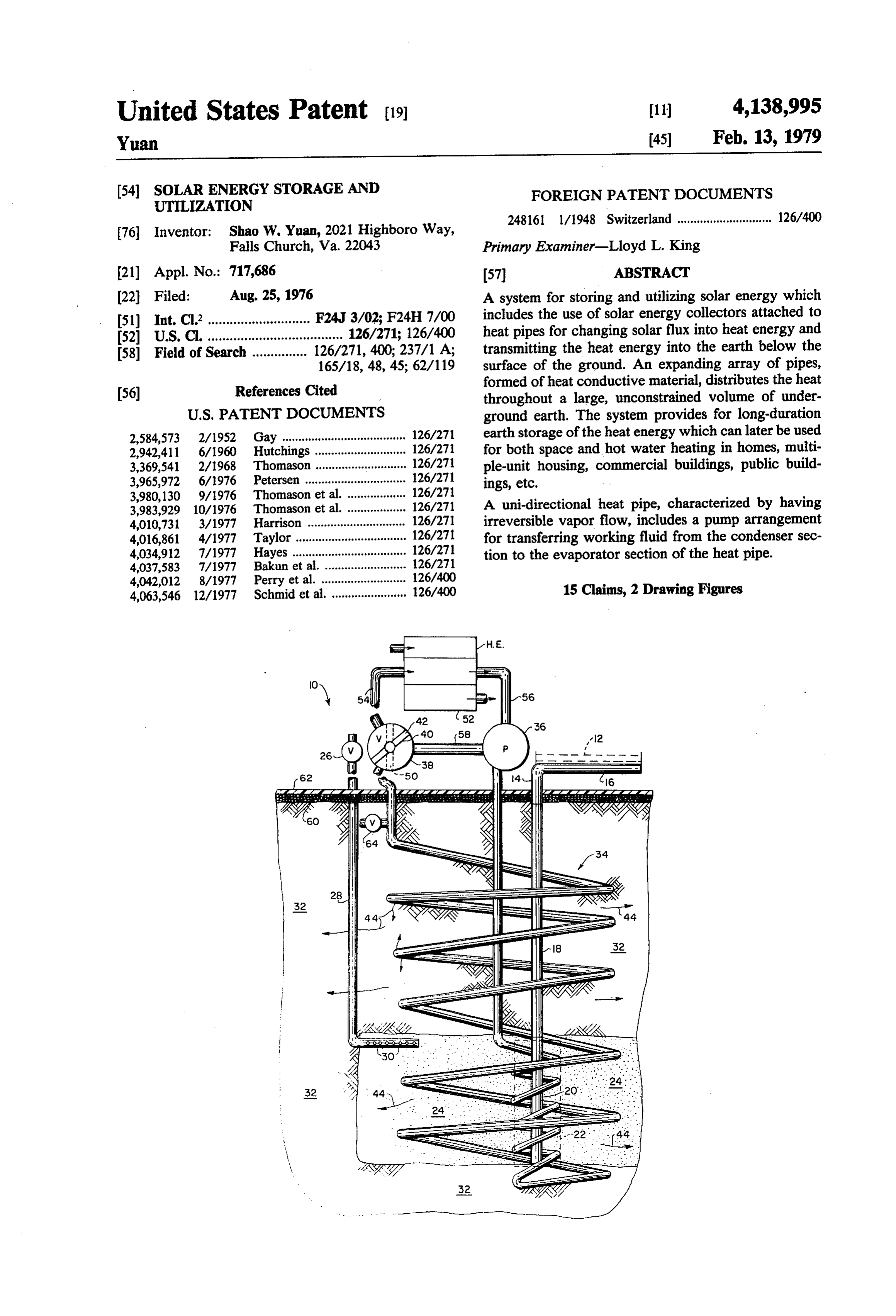
United States Patent (19) 11) 4,138,995 Yuan 45) Feb. 13, 1979 (54). SOLAR ENERGY STORAGE AND FOREIGN PATENT DOCUMENTS
UTILIZATION
248161 l/1948 Switzerland............................. 126/400 76 Inventor: Shao W. Yuan, 2021 Highboro Way,
Falls Church, Va. 22043 Primary Examiner-Lloyd L. King (21) Appl. No.: 717,686 57 ABSTRACT (22 Filed: Aug. 25, 1976 A system for storing and utilizing solar energy which 51) Int. C.’............................ F24J 3/02; F24H 7/00 includes the use of solar energy collectors attached to 52 U.S.C. ..................................... 126/271; 126/400 heat pipes for changing solar flux into heat energy and 58) Field of Search ............... 126/271, 400; 237/1 A; transmitting the heat energy into the earth below the 165/18, 48, 45; 62/119 surface of the ground. An expanding array of pipes,
formed of heat conductive material, distributes the heat throughout a large, unconstrained volume of under
2,584,573 2/1952 Gay ..................................... 126/271 earth storage of the heatenergy which can later be used 2,942,411 6/1960 Hutchings ... ... 126/27 for both space and hot water heating in homes, multi 3,369,541 2/1968 Thomason ... ... 126/271 ple-unit housing, commercial buildings, public build 3,965,972 6/1976 Petersen ........... ... 126/271 ings, etc.
3,980,130 9/1976 Thomason et al. .. ... 126/271 3,983,929 10/1976 Thomason et al... ... 126/271 A uni-directional heat pipe, characterized by having 4,010,731 3/1977 Harrison .............. ... 126/271 irreversible vapor flow, includes a pump arrangement 4,016,861 4/1977 Taylor ...... ... 126/271 for transferring working fluid from the condenser sec 4,034,912 7/1977 Hayes....... ... 26/27 tion to the evaporator section of the heat pipe. 4,037,583 7/1977 Bakun et al. . ... 126/271 4,042,012 8/1977 Perry et al. .. ... 126/400 4,063,546 12/1977 Schmid et al. ...................... 126/400 15 Claims, 2 Drawing Figures
Page 2
Drawing sheet — no readable text.
Page 3
Drawing sheet — no readable text.
Page 4
Part of the invention system also relates to a novel
SOLAR ENERGY STORAGE AND UTILIZATION heat pipe characterized by having uni-directional irre
BACKGROUND OF THE INVENTION
versible vapor flow, and having a unique compact sys tem for moving working fluid from the condenser sec
Until the nineteen-seventies, solar heating received 5 tion to the evaporator system.
only scattered, spasmodic attention because it was not The invention comtemplates a novel system for stor price competitive with the use of fossil fuels. Renewed ing and utilizing solar energy wherein the system com interest in solar energy has developed during the past prises a collector means for collecting solar energy and few years as a result of increasing costs of energy from changing the solar energy to heat, means for transmit fossil fuels, the problems of depletion of resources, and O ting the heat from the collector means to a location the degradation of the environment. Although solar below the surface of the ground, and a distributing energy may be considered as a new and unconventional means disposed within the ground for distributing the resource, it has been used for many centuries for drying heat from the mentioned location throughout a consid agricultural products, heating water, etc. erable volume of the ground for raising the temperature Prior art solar heating systems are generally accom 15 of the considerable volume of ground to thereby estab plished by placing large collector plates on the roof and lish a heat reservoir.
side structure of buildings. Liquids, such as water, are For accomplishing for foregoing objective, the in piped through the collector, heated to a higher tempera vention contemplates the use of solar collectors, a heat ture, and subsequently circulated through a building pipe or pipes for transmission of the solar heat energy to and used as a space and tap-water heating medium. 20 the storage ground, and piping loops for both transmis Such a system may be useful during the sunlight hours sion and storage of heat in the system, and extraction of but loses its effectiveness after sundown. In a more heat from the storage ground for space heating and hot elaborate application of the same principle, it has been water heating. The heat pipe functions in the system as suggested to place large tanks of water, rocks, stones, 25 a sort of rectifier, for changing solar flux to heatenergy, etc., in the ground and have heated water from the solar and allowing the heat energy to flow with the least collector fed into the tanks, where the heat energy is possible resistance from the evaporator section of the stored and utilized for space and hot water heating. But, heat pipe to a desired depth underground during the during prolonged cloudy or rainy weather, such a sys period of time when the sun is shining, but prevents the tem loses its effectiveness because of its incapacity to 30 reverse flow of heat energy when the temperature store more than a few days' supply of heat energy. above the ground is lower than that of the storage Furthermore, during the winter period when the heat is ground.
most desirable, the efficiency of the solar radiation is Accordingly, an important object of the invention is much less than that of summer months, and heat loss to provide for long-duration earth storage of solar en from the collector to the surroundings is much greater. 35 ergy which can be used for both space heating and hot In short, currently known solar-heating systems must be water heating systems, year-round, in multiple-unit installed in addition to, not instead of, conventional housing, public buildings such as schools, etc., commer heating systems. cial buildings or single dwellings. The earth, as a thermal storage reservoir, has several Another object of the invention is to provide a highly interesting attributes. First, heat capacities are ex efficient means for transferring solar energy from solar tremely large because of the large available mass. For flux collectors into the ground for storage of heat example, in a volume of one acre of land, 15 feet deep, through the use of novel heat pipe including an evapo at a temperature difference of 50 F. the energy flux is rator section, an adiabatic section, a condenser section estimated to be 1.49 x 10'BTU. The area of one acre is and a working fluid, wick means disposed only in the much larger than an average house. Specifically, it is 45 evaporator section and condenser section, and pump over 20 to 40 times larger than the average house of means for transferring the working fluid, after phase sizes from 2,000 ft to 1,000 ft. Assuming a winter heat change from vapor to liquid from the condenser section ing requirement of 60 x 10 BTU for a small house, to the evaporator section.
such a volume of earth would be able to store sufficient Further, the invention provides such a heat pipe heat to supply approximately 25 homes. 50 wherein the pump means includes a fluid line extending Another attribute of the earth is its extremely low from the condenser section to the evaporator section thermal conductivity. Since the storage system may be and a pump is connected in the fluid line. unbounded in the downward and sideward directions as A further, and important, object of the invention is to opposed to the confined, insulated and water-proofed provide such a heat pipe wherein the pump is disposed constructions of the conventional designs, the low ther 55 at a location remote from the condenser section. mal conductivity of the earth restricts losses in those A still further object of the invention is to provide a directions. It has been approximated that the total en novel heat pipe wherein the evaporator section and the ergy in the solar flux over one acre of area, for one condenser section each include an outer casing formed summer season, is 1.2 x 100 BTU; these are approxi of heat conductive material, and the adiabatic section mately the heating requirements for 200 houses. It can has at least a portion thereof formed of a poor heat therefore be seen that the theoretically available energy conductive material for precluding transfer of heat by from the sun is extremely high. conduction between the condenser section and the evaporator section.
SUMMARY OF THE INVENTION A further object of the invention is to provide a large The present invention relates to a system for collect 65 thermal storage reservoir in the unprepared earth and to ing, storing and utilizing solar energy, and more partic utilize the stored energy for year-round space heating ularly, relates to a system which utilizes the earth, or and hot water heating substantially or completely with ground, as a long-duration storage for heat energy. out the aid of conventional heating systems.
Page 5
A still further object of the invention is to provide a 34 is comprised of a closed loop in which is located a solar heating system which need not be an integral part pump 36 and a two-way valve 38 having a vane 40 of the solar heated home, if so desired, thus having no shown by solid lines located in a first position 42. In adverse impact on the esthetics of the home. order to transmit heat energy from the location 22 A still further object is to provide an efficient means throughout the soil 32, the pipe 34 is completely filled to collect and store an abundance of solar energy during with heat transfer fluid, such as water and the like, the the summer season for subsequent winter use when the heat transfer fluid being circulated within the pipe 34 efficiency of collecting solar energy is extremely low. downwardly from the pump 36 and spirally about the Further objects and advantages of my invention will condenser section 20 throughout the location 22. Dur become apparent from an understanding of the follow 10 ing this time, the heat transfer fluid picks up heat and ing detailed description of preferred embodiments of then carries it throughout the expanding array of pipe my invention. 34 to distribute the heat throughout a large volume of
DESCRIPTION OF THE DRAWINGS
the earth's soil 32. This distibution of the heat is gener ally indicated by the plurality of the arrows 44. It will
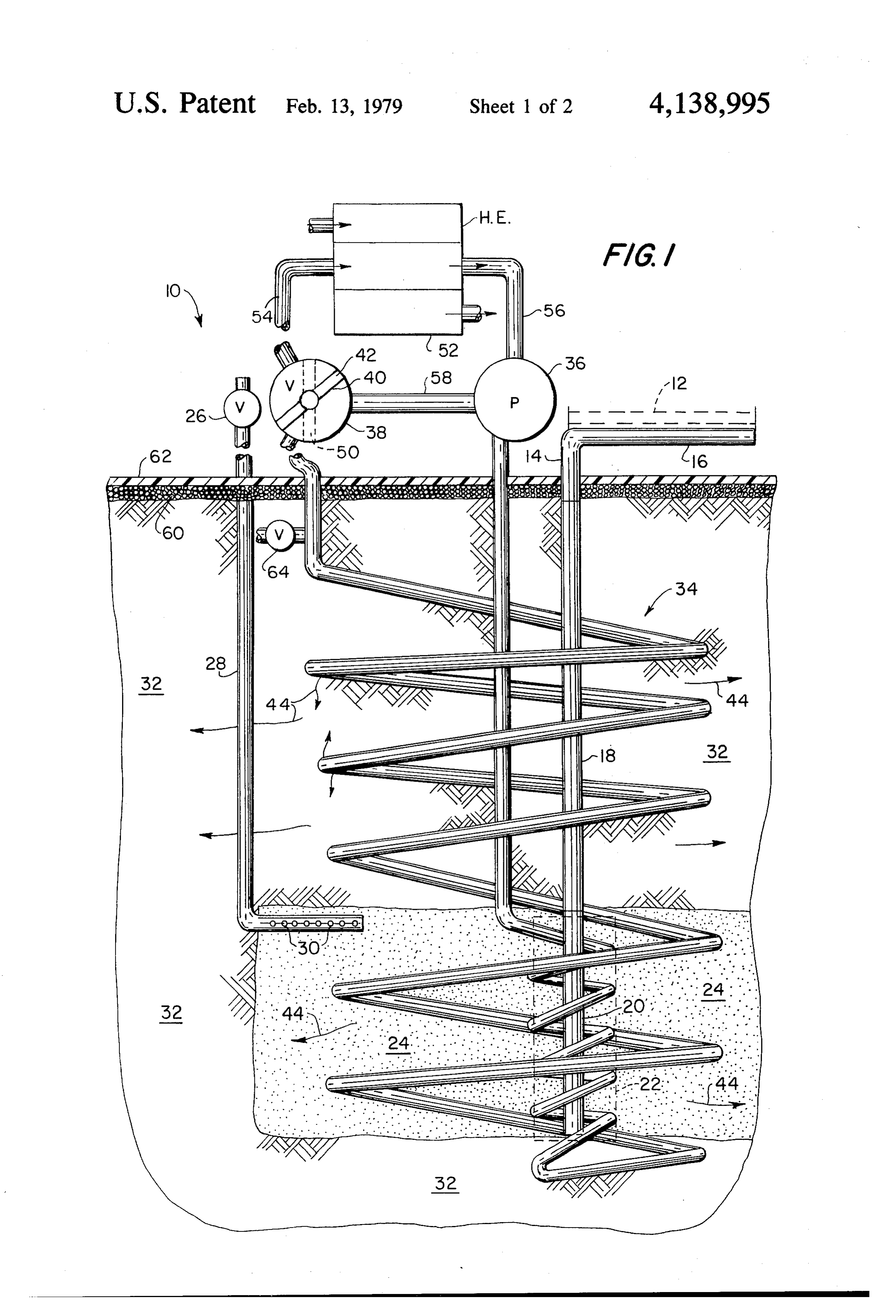
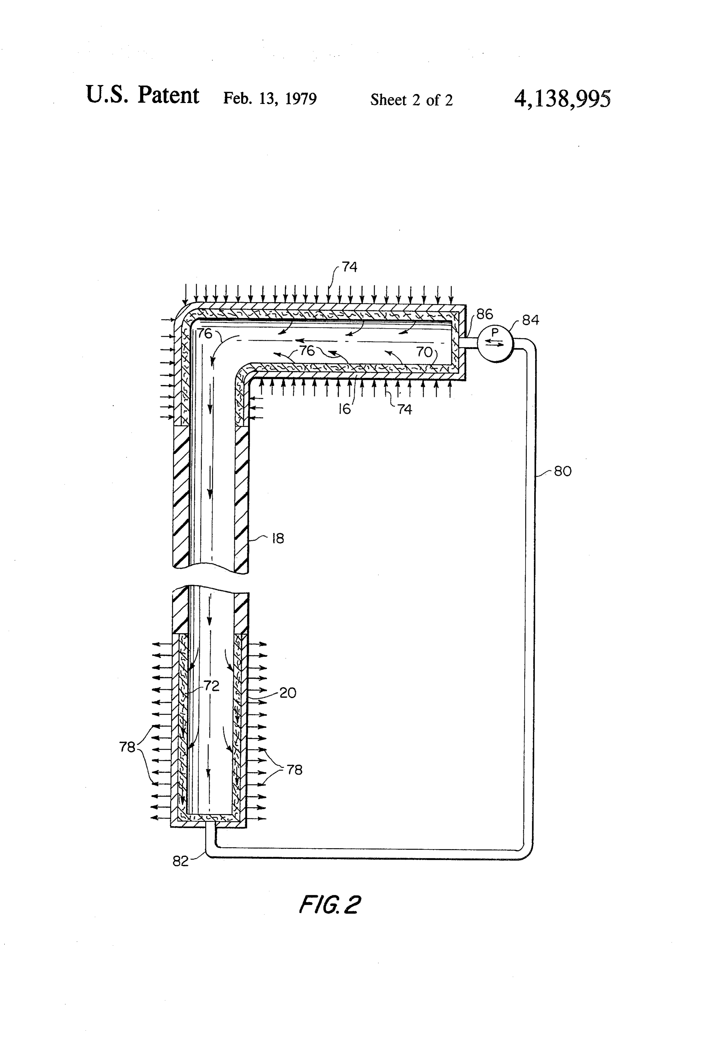
FIG. 1 is a diagrammatic sectional view of a system 15 be appreciated that after the system has been operating for collecting, storing and utilizing solar energy in ac for a period of time, the temperature of the sand 24, the cordance with the present invention. soil 32, and beyond, will be elevated to a sufficiently FIG. 2 is a diagrammatic vertical section of a heat high degree such that adequate heat supply may be later pipe constructed in accordance with the present inven extracted for subsequent use.
tion. 20When it is desired to use some of the heat that has been stored in the soil 32, the valve vane 40 is moved to
DESCRIPTION OF THE PREFERRED the dotted line position 50. As one example of apparatus EMBODIMENTS for using the storage heat, a heat exchanger 52 is con Referring to FIG. 1, the novel collection, storage and nected across the valve 38 and the pump 36 by pipes 54 utilization system, generally indicated by the numeral 25 and 56 so that the heat transfer fluid does not pass di 10, includes a conventional solar collector 12 (shown in rectly from the valve 38 to the pump 36 through a broken lines) which collector 12 may be planar, para connecting pipe 58. It is, of course, to be understood bolic, or any other type of collector, for collecting solar that the hot water in pipe 54 gives up its heat energy as energy and transferring the heat energy thereof to a it passes through the heat exchanger 52, becomes heat pipe 14. The heat pipe includes an evaporator sec 30 cooler, and passes downwardly through the pump 36 tion 16, adiabatic section 18, and a condenser section. 20. into the array of pipe 34 to become heated and again The particular details of construction for the heat pipe return to the heat exchanger 52.
14 will be later described in connection with the show In order to increase the efficiency of the heat storage ing in FIG. 2. Briefly, however, energy is absorbed by system, a layer of insulating material 60 is disposed the evaporator section 16 and transferred through the 35 about on the surface of the earth, and preferably, the adiabatic section 18 down to the condenser section 20, insulating material 60 is covered by a sheet, or sheets, of which section 20 may be, depending upon circum black plastic 62, or the like, to serve as a vapor barrier stances, located at a depth below the earth's surface a and also to aid in collecting additional heat from the distance of approximately 5 feet to 30 feet, or more. solar flux and transmitting such heat into the soil 32 and At a location 22, represented by a volume of earth in absorbing more heat because black materials charac encompassed within the broken line rectangle, heat is teristically have the highest heat absorbtivities. absorbed from the condenser section 20, where the While the foregoing description of the invention has phase change from vapor to liquid is taken place. Heat been limited to only a single array of pipe 34, it will be energy is transmitted in all directions from this location readily understood that multiple arrays of pipe 34 and 22, thereby cooling the condenser section 20 and caus 45 additional heat pipes 14 may be connected to the system ing the heat energy to be transferred to the surrounding through a valve 64.
earth. One important feature of the present invention is FIG. 2 illustrates the constructional details of a pre to surround the condenser section 20 with material ferred heat pipe 14 which is utilized in the system 10 of which has a higher coefficient of heat conductivity than FIG.1. The heat pipe 14 includes an evaporator section the normal soil. One such manner is illustrated by the 50 16, an adiabatic section 18, and a condenser section 20 as provision of a relatively small volume of granular sand well as containing a working fluid (not illustrated). The 24, and the like, which may have the moisture content evaporator section 16 is lined with a wick 70 and the thereof increased by piping water, or the like, through a condenser section 20 is lined with a wick 72. It is to be control valve 26 downwardly through a supply pipe 28 noted that the adiabatic section 18 is not lined with any and outwardly through a series of holes 30. It will be 55 similar wick. The wick 70 and 72 may be metal, such as understood that the moist sand 24 will aid in transmit wire screen, sintered metal powder or fiber, or perfo ting heat outwardly from the location 22 to the sur rated sheets, or it may be a non-metallic material such as rounding unprepared earth soil, generally designated by felt, cloth, or fiber glass. The working fluid may be the numeral 32. It is understood that other types of heat water, ammonia, acetone, fluorocarbons (refrigerants), conductive material, such as metal and the like, which alcohols, and various liquid metals. However, only may also be in the form of fins extending outwardly enough working fluid to saturate the wick is introduced from the condenser section 20 may be be used instead into the heat pipe. The choice of container, wick mate of, or in combination with, the moist sand 24. rial, and working fluid combination is based on the In addition to the foregoing described manner of operations and design criteria of the heat pipe applica transmitting heat energy from the condenser section 20 65 tion.
to the surrounding soil 32, the present invention also In evaporator section 16 heatenergy, indicated by the includes the provision of an expanding array of pipe (or arrows 74, is received from the solar collector 12 (FIG. pipes), generally indicated by the numeral 34. The pipe 1) and is transferred by conduction through the outer
Page 6
wall of the evaporator section 16. The heat energy 74 heat storage volume substantially greater than that causes the working fluid to vaporize, as indicated by the formed by the transmitting means alone; and arrows 76. The vaporized working fluid then flows control means including valve means in said distribut downwardly through the adiabatic section 18 to the ing means, and heat exchange means in fluid flow condenser section 20 where the vapor condenses and connection with said valve means for controlling the heatenergy is transmitted outwardly to the wick 72 flow of said heat transfer fluid in said distributing through the wall of the condenser section 20, all as is means and thus permitting said distributing means indicated by the arrows 78. It is to be understood this to function as means for extracting heat from the heat, as indicated by the arrows 78, is the heat given up 10 2. ground.
A system as defined in claim
1 wherein said trans in the location 22 of FIG.1. mitting means for transmitting said heat from said col In order that heat pipe 14 operates in a continuous manner, it is necessary that the working fluid conden lector means comprises a heat pipe.
sate in the condenser section 20 be returned to the evap pipe 3. A system as defined in claim 2 wherein said heat orator section 16. This return of working fluid is pro meansincludes an evaporator section at said collector and a condenser section at said location below vided by the provision of a return line 80 which is con nected to a port 82, at the bottom of the condenser the4.surface of the ground.
A system as defined in claim 1 including heat insu section 20, and connected to a pump 84 which is, in turn, connected to a port 86 at the evaporator 16. While lating means located adjacent the surface of the ground the pump 84 is indicated as being a reversible pump, so 20 for minimizing the heat losses from said volume of ground into the atmosphere.
that the heat pipe 14 is useful in other modes of opera tion, it is to be understood that when the heat pipe 14 is 5. A system as defined in claim 1 including heat ex used in the environment of the system 10, of FIG. 1, the traction means for extracting heat from said heat reser pump 84 is operated only in the direction to return voir and delivering said heat to a desired location. working fluid from the condenser section 20 to the 25 6. The system as defined in claim 1 wherein the lateral evaporator section 16. This is an important part of the area which defines said volume is at least one acre. system 10 so that, when the collector 12 is not operating 7. The system as defined in claim 1 wherein said and the ambient temperature around the evaporator 16 volume is at least 30 feet deep.
is lower than the ground temperature around the con 8. The system as defined in claim 1 wherein said denser section 20, the heat pipe 14 is irreversible; in 30 piping system includes a spirally wound array of heat other words, heat energy is not transmitted upwardly conductive piping.
through the adiabatic section 18 and lost to the atmo of9.heat The system as defined in claim 8 wherein said array conductive piping comprises a spirally wound sphere through the evaporator section 16.
When the solar energy is not available, or during array of heat conductive piping having the axis of the extremely cold weather, the pump 84 will be shut off 35 spiral generally extending in the direction of the local automatically by a thermostatic control (not shown). gravity gradient.
This prevent the reverse vapor flow in order to avoid 10. The system as defined in claim 9 wherein the axis heat losses from the earth reservoir to the surrounding of the spiral extends in a generally vertical direction. environment. As an additional measure to prevent heat distribution11. The system as defined in claim 10 including liquid loss by axial conduction of heat upwardly through the means for introducing a liquid to said mate heat pipe 14, the adiabatic section 18 is made of a poor rial12.toThe provide for a high level of thermal conductivity. system as defined in claim 1 wherein said heat heat conductive material. Thus, the condenser section 20 is insulated from the evaporator section 16. transfer fluid consists essentially of water. While a preferred system and a preferred heat pipe 13. The system as defined in claim 1 in which said for use in such system has been illustrated and de 45 zone transmitting means at said location is surrounded by a scribed, it is to be understood that various changes and of material having a thermal conductivity that is arrangement of parts may be made without departing higher 14. A than the thermal conductivity of natural soil.
system for storing and utilizing solar energy from the spirit and scope of the invention as defined in comprising:
the appended claim subject matter. collector means for collecting solar energy and
1. A system for storing and utilizing solar energy changing said solar energy to heat; comprising: transmitting means including a closed loop piping collector means for collecting solar energy and system for transmitting said heat from said collec changing said solar energy to heat; tor means to a location below the surface of the ground;
transmitting means for transmitting said heat from 55 distributing said collector means to a location below the surface means comprising a closed loop piping of the ground; systern extending out from said location into the distributing means comprising a closed loop piping surrounding soil, and means for causing a heat system extending out from said location into the transfer fluid to flow within said piping system, surrounding soil, and means for causing a heat said distributing means positioned adjacent said transfer fluid to flow within said piping system, transmitting means at said location and in efficient said distributing means positioned adjacent said heat transfer relationship with said transmitting transmitting means at said location and in efficient means, said distributing means extending through a heat transfer relationship with said transmitting volume of said ground for raising the temperature means, said distributing means extending through a 65 of said volume of ground thereby establishing a volume of said ground for raising the temperature stored heat reservoir, said heat reservoir having a of said volume of ground thereby establishing a heat storage volume substantially greater than that stored heat reservoir, said heat reservoir having a formed by the transmitting means alone;
Page 7
means for increasing the rate of heat transfer from to function as means for extracting heat from the said transmitting means to said distributing means ground.
above the rate of heat transfer of normal soil at said 15. The system as defined in claim 14 in which said location; and means for increasing the rate of heat transfer includes a control means including valve means in said distribut volume of granular sand surrounding said location and ing means, and heat exchange means in fluid flow a water supply means including a control valve for connection with said valve means for controlling increasing the moisture content of said volume of gran flow of said heat transfer fluid in said distributing ular sand.
means and thus permitting said distributing means
Provenance
- Collection
- Cited prior art
- Original PDF
- patentimages.storage.googleapis.com →
- Filed
- 1976-08-25
- Pages
- 7
- Method
- pdftotext (the PDF's own text layer) + pdftoppm 300dpi page scans
- Source
- Google Patents bibliographic record
- Granted
- 1979-02-13
- Inventors
- Shao W. Yuan
- Transcribed from
- patentimages.storage.googleapis.com →