patent · US3703958
Eddy current apparatus and method of application to a conductive material
28 November 1972
Page 1 — bibliographic record
United
Kolm
States Patent is 3,703,958
54 EDDY CURRENT APPARATUS AND 3,365,522 1/1968 Inoue......................... 72/56 X METHOD OF APPLICATION TO A 2,834,470 5/1958 Jones.........................210/222 CONDUCTIVE MATERIAL 3,277,631 10/1966 Sunnen............................55/3 72 Inventor: Henry H. Kolm, Wayland, Mass. 3,279,602 10/1966 Kottenstette et al........210/42
(73) Assignee: Massachusetts Institute of Technolo gy, Cambridge, Mass. Primary Examiner-J. H. Mack 22 Filed: Aug. 11, 1969 Assistant Examiner-T. Tufariello (21) Appl. No.: 849,128 Attorney-Thomas Cooch, Martin M. Santa and Robert Shaw
Related U.S. Application Data (57) ABSTRACT (63) Continuation-in-part of Ser. No. 761,048, Sept. Eddy current apparatus is disclosed for applying a
force to a conductive material. The apparatus employs (52) U.S. Cl.........................210/65,72/56, 204/186, two magnetic fields. The first, a background or soak 210/42, 317/123,324/40 ing field, is continuous or slow rising and has a skin 51 int. Cl........ B03c S/00, B01d 37/00, B21d 26/02 depth that is greater than the dimension of the materi 58) Field of Search........210/42, 65,222, 223; 55/3; al in the direction of field penetration. The second is 204/186-191, 193,309; 72/56 fast-rising and has a skin depth that is less than said dimension. The two fields are timed or phased and 56 References Cited oriented with respect to each other to produce the force in a desired direction. Thus, the conductive
UNITED STATES PATENTS material can be particles in a slurry or a sheet of con 3,092,165 6/1963 Harvey......................72/56 X ductive material and the force applied thereto can be 3,108,325 10/1963 Harvey......................72/56 X toward or away from the field source depending upon 3,210,842 10/1965 Schwinghamer........... 72/56X ... the timing or phasing of the fields and the orientation thereof.
3,212,311 10/1965 Inoue.........................72/56X 3,214,832 1 1/1965 Schwinghamer...........72/56X 14 claims, 5 Drawing Figures
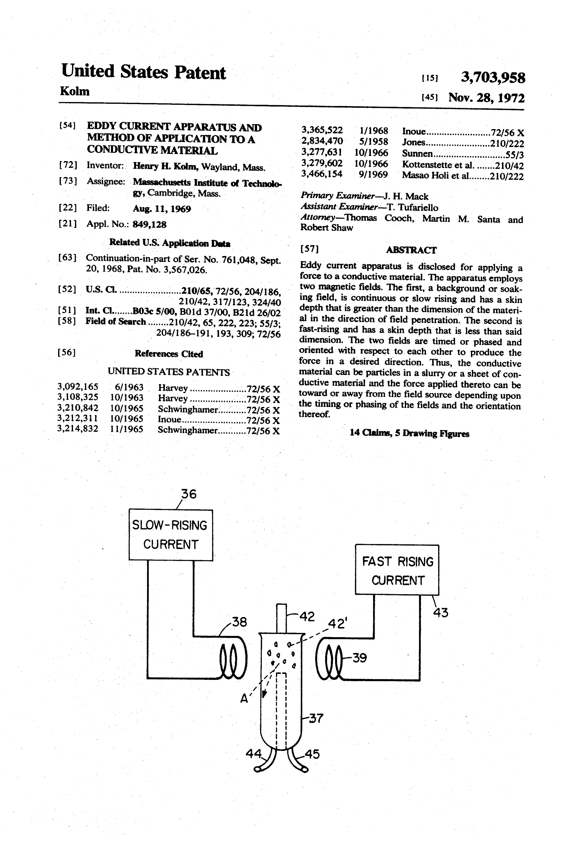
CURRENT
FAST RISING
CURRENT
Page 2
Drawing sheet — no readable text.
Page 3
Drawing sheet — no readable text.
Page 4
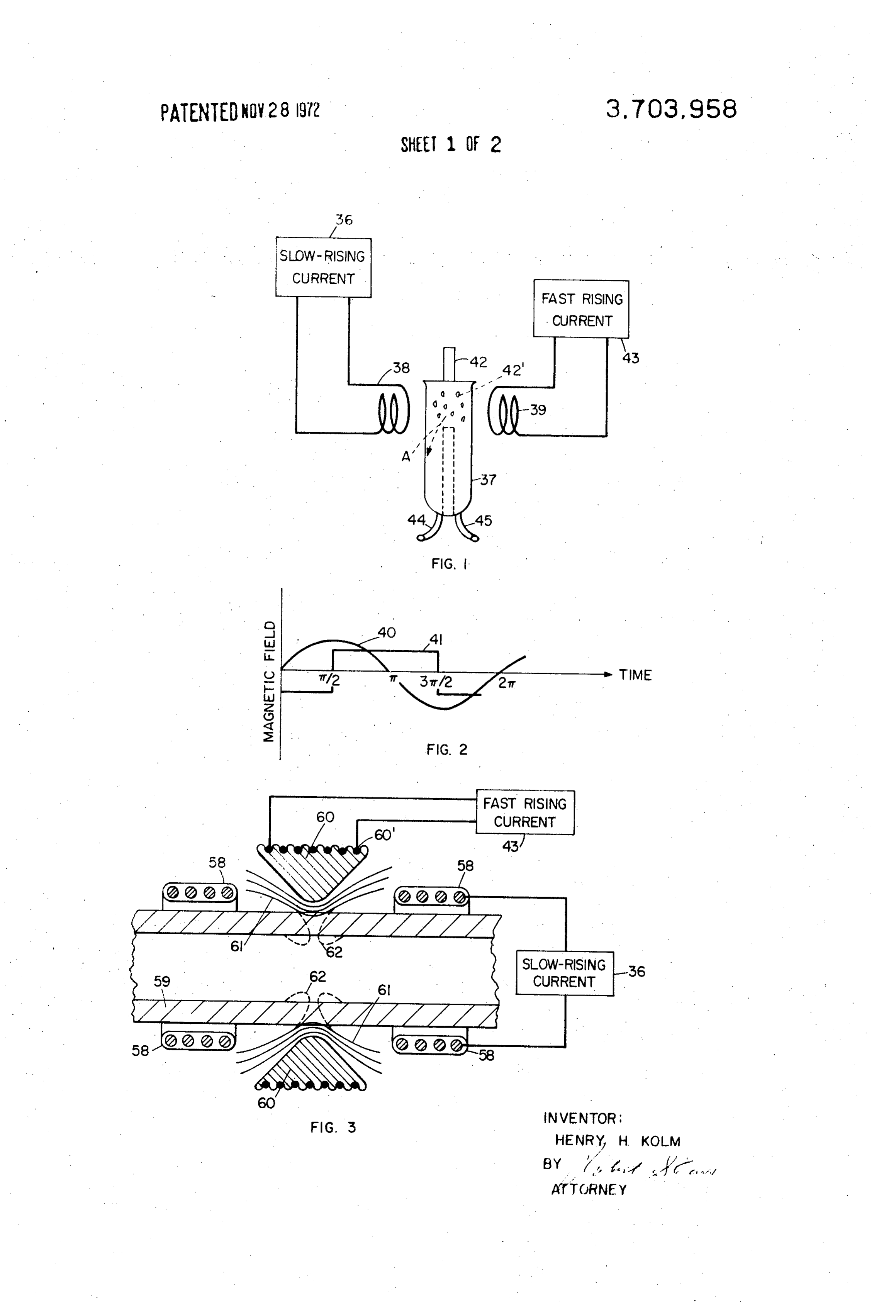
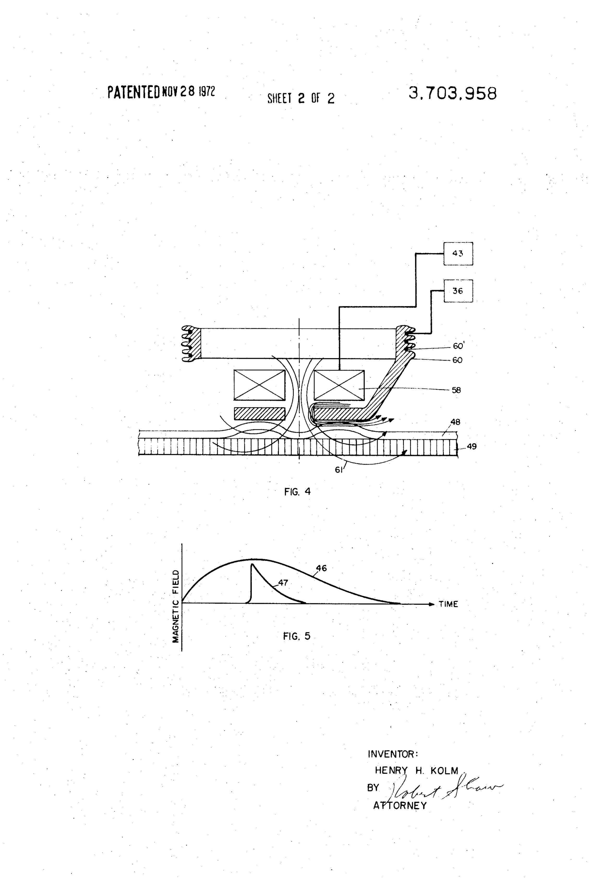
EDDY CURRENT APPARATUS AND METHOD OF FIG. 3 is a schematic representation to show eddy APPLICATION TO A CONDUCTIVE MATERIAL current means analogous to that shown in FIG. 1 in an This is a continuation-in-part of application Ser. No. electromagnetic shear or hammer apparatus; 761,048 filed on Sept. 20, 1968 now U.S. Pat. No. FIG. 4 is a schematic representation to show eddy 3,567,026 in the name of the present inventor and is 5 current means for applying a traction force to a con being filed as a result of a requirement for division. . ductive skin bonded to a supporting structure for the This invention was made in the course of work per purpose of proof-loading the skin bond so as to deter formed under a contract with the Air Force Office of mine non-destructively whether the bond will Scientific Research. , withstand a minimum required force, and to accom The present invention relates to electric eddy-cur 10 plish this non-destructive test without access to the in rent apparatus adapted to apply a force to a conductive terior of the structure being tested; and material and employs two magnetic fields, the timing FIG. 5 shows a preferred shape of magnetic pulsed and orientation of the fields determining whether the fields applied by the eddy current means shown in resulting force produced by the apparatus is one of at 15 FIGS. 3 and 4.
traction or repulsion. Referring now to FIG. 1, eddy current apparatus is The present disclosure is concerned, broadly, with shown for applying a force to a conductive material 42' eddy-current apparatus that may be used, for example, which in the embodiment of FIG. comprises particles to apply forces to conductive materials such as conduc suspended in a non-conductive medium which may be tive components in a slurry or other fluid carrier or to 20 a liquid or a gas carrier. Two periodically time varying conductive tubes, plates and the like. The apparatus, as magnetic fields are introduced to the medium in a discussed in said application, is capable of applying manner unidirectional forces upon materials toward or away tation oflater discussed herein and the timing and orien the fields with respect to one another deter from the eddy current source, as the case may be, and mine whether the force thereby produced is toward or the magnitudes of such forces are far greater than have 25 away from the source of the magnetic fields. been heretofore possible. As further discussed, it can The apparatus shown schematically in FIG. 1 com be employed to remove conductive particles from a prises a non-conductive tank 37 (having an inlet pipe fluid medium, but is useful, as well, for shearing metal 42) to receive a slurry and to remove therefrom con and, also, as hammer apparatus for forming metal. In ductive components whether magnetic or non-mag the latter situation the metal can be deformed (as well 30 netic from the slurry. A slow rising field, as represented as formed) by an accurately reproducible force for by the wave 40, is furnished by a coil 38 which is ener proof-loading or for non-destructive testing of metal gized by a current source 36; and a fast rising field, as joints and the like. represented by the wave 41, is furnished by a coil 39 Accordingly, an object of the present invention is to which is energized by a current source 43. The conduc provide a novel eddy-current apparatus adapted to 35 tive components 42" (which may be small metal parti furnish unidirectional repulsive or attractive forces to cles) within the slurry are propelled to travel in the conductive materials, the magnitude of such forces direction of the arrow designated A to pass from the being far greater than have been heretofore possible. tank 37 through an outlet 44; the usable slurry passes A further object is to provide eddy current apparatus through adapted to remove conductive particles or components 40 ticle 42'anwill outlet 45. The force of any conductive par be to the left or right depending on from a fluid carrier, gas or liquid. whether the wave 40 leads or lags the wave 41 in time A still further object is to provide apparatus that may be used to deform and/or shear conductive plates, and on the relative orientation of the coils 38 and 39. Unlike devices with no background field or a continu tubes and the like.
ous background field and in which the time varying
Other objects are discussed hereinafter and are par field must be asymmetric
ticularly delineated in the appended claims. to provide a unidirectional By way of summary, the objects of the invention are net force, the present device, though having symmetric attained, broadly, in double-field eddy current ap fields, produces a unidirectional force. And the force is paratus for applying a unidirectional force to a conduc 50 maximized because the instant at which the rate of tive material that comprises, in combination, coil change is maximal coincides with the instant at which means, a source of current adapted to connect to the the field is maximal. Thus, the induced eddy currents coil means and produce thereby a magnetic field hav reach their maximum at a time when the magnetic field ing a skin depth that is greater than the dimension of is maximum, which optimizes use of the potentially the material in the direction of field penetration, a available force. The use of high intensity pulsed fields, source of abruptly rising current adapted to connect to 55 since the background field is needed for only a brief in the coil means and produce thereby a fast-rising mag stant of time, represents a substantial saving of power netic field having a skin depth that is less than said over a continuous background field. In addition, as ex dimension of the material. plained herein, the period or rise time of the varying The invention will now be discussed in connection 60 field is systematically matched to the object to be acted with the accompanying drawing in which: on, in such a way as to achieve the proper skin depth or FIG. 1 is a schematic representation of eddy current penetration depth of the induced eddy currents. The apparatus used in connection with removal of conduc eddy current apparatus discussed here represents an tive components or particles from a slurry; improvement over the prior art in that it uses two FIG. 2 is a graph showing a sinusoidal wave to pro 65 separately controlled pulsed or periodically varying vide a slow-rising magnetic field for the eddy current magnetic fields, one having a substantially fast rise-time apparatus of FIG. 1 and a square wave to provide a fast to induce eddy currents of appropriate skin depth in rising field therefor; the particular object or particle to be acted on, and the
Page 5
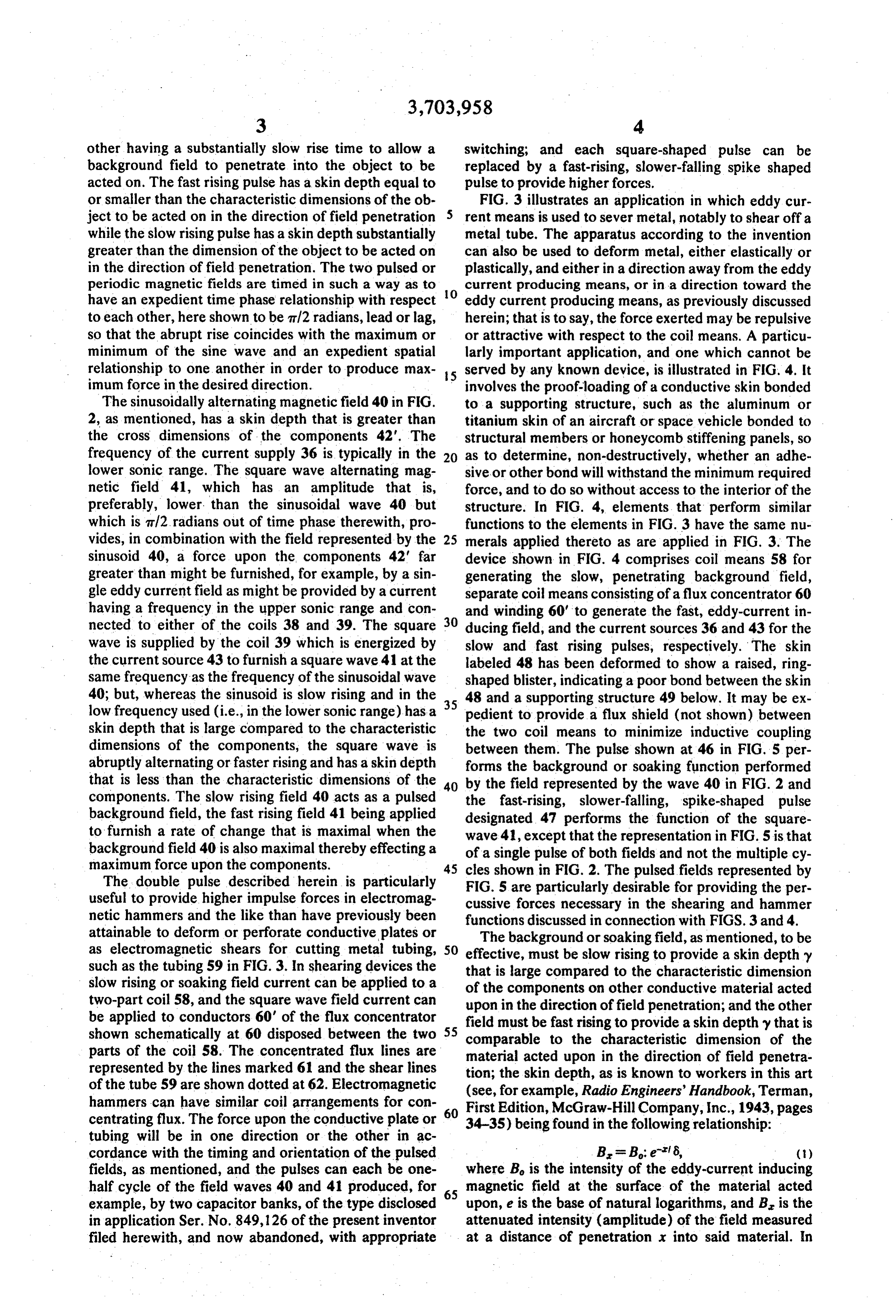
other having a substantially slow rise time to allow a switching; and each square-shaped pulse can be background field to penetrate into the object to be replaced by a fast-rising, slower-falling spike shaped acted on. The fast rising pulse has a skin depth equal to pulse to provide higher forces. or smaller than the characteristic dimensions of the ob FIG. 3 illustrates an application in which eddy cur ject to be acted on in the direction of field penetration rent means is used to sever metal, notably to shear off a while the slow rising pulse has a skin depth substantially metal tube. The apparatus according to the invention greater than the dimension of the object to be acted on can also be used to deform metal, either elastically or in the direction of field penetration. The two pulsed or plastically, and either in a direction away from the eddy periodic magnetic fields are timed in such a way as to O current producing means, or in a direction toward the have an expedient time phase relationship with respect eddy current producing means, as previously discussed to each other, here shown to be m/2 radians, lead or lag, herein; that is to say, the force exerted may be repulsive so that the abrupt rise coincides with the maximum or or attractive with respect to the coil means. A particu minimum of the sine wave and an expedient spatial larly important application, and one which cannot be relationship to one another in order to produce max 15 served by any known device, is illustrated in FIG. 4. It imum force in the desired direction. involves the proof-loading of a conductive skin bonded The sinusoidally alternating magnetic field 40 in FIG. to a supporting structure, such as the aluminum or 2, as mentioned, has a skin depth that is greater than titanium skin of an aircraft or space vehicle bonded to the cross dimensions of the components 42'. The structural members or honeycomb stiffening panels, so frequency of the current supply 36 is typically in the 20 as to determine, non-destructively, whether an adhe lower sonic range. The square wave alternating mag sive or other bond will withstand the minimum required netic field 41, which has an amplitude that is, force, and to do so without access to the interior of the preferably, lower, than the sinusoidal wave 40 but structure. In FIG. 4, elements that perform similar which is af2. radians out of time phase therewith, pro functions to the elements in FIG. 3 have the same nu vides, in combination with the field represented by the 25 merals applied thereto as are applied in FIG. 3. The sinusoid 40, a force upon the components 42' far device shown in FIG. 4 comprises coil means 58 for greater than might be furnished, for example, by a sin generating the slow, penetrating background field, gle eddy current field as might be provided by a current separate coil means consisting of a flux concentrator 60 having a frequency in the upper sonic range and con and winding 60' to generate the fast, eddy-current in nected to either of the coils 38 and 39. The square 30 ducing field, and the current sources 36 and 43 for the wave is supplied by the coil 39 which is energized by slow and fast rising pulses, respectively. The skin the current source 43 to furnish a square wave 41 at the labeled 48 has been deformed to show a raised, ring same frequency as the frequency of the sinusoidal wave shaped blister, indicating a poor bond between the skin 40; but, whereas the sinusoid is slow rising and in the 35 48 and a supporting structure 49 below. It may be ex low frequency used (i.e., in the lower sonic range) has a pedient to provide a flux shield (not shown) between skin depth that is large compared to the characteristic the two coil means to minimize inductive coupling dimensions of the components, the square wave is between them. The pulse shown at 46 in FIG.5 per abruptly alternating or faster rising and has a skin depth forms the background or soaking function performed that is less than the characteristic dimensions of the 40 by the field represented by the wave 40 in FIG. 2 and components. The slow rising field 40 acts as a pulsed the fast-rising, slower-falling, spike-shaped pulse background field, the fast rising field 41 being applied designated 47 performs the function of the square to furnish a rate of change that is maximal when the wave 41, except that the representation in FIG. 5 is that background field 40 is also maximal thereby effecting a of a single pulse of both fields and not the multiple cy maximum force upon the components.
The double pulse described herein is particularly cles shown in FIG. 2. The pulsed fields represented by
FIG.
useful to provide higher impulse forces in electromag cussive 5 are particularly desirable for providing the per forces necessary in the shearing and hammer netic hammers and the like than have previously been functions discussed in connection with FIGS. 3 and 4. attainable to deform or perforate conductive plates or The background or soaking field, as mentioned, to be as electromagnetic shears for cutting metal tubing, 50 effective, must be slow rising to provide a skin depthy such as the tubing 59 in FIG. 3. In shearing devices the that is large compared to the characteristic dimension slow rising or soaking field current can be applied to a of the components on other conductive material acted two-part coil 58, and the square wave field current can upon in the direction of field penetration; and the other be applied to conductors 60' of the flux concentrator field must be fast rising to provide a skin depthy that is shown schematically at 60 disposed between the two 55 comparable to the characteristic dimension of the parts of the coil 58. The concentrated flux lines are material acted upon in the direction of field penetra represented by the lines marked 61 and the shear lines tion; the skin depth, as is known to workers in this art of the tube 59 are shown dotted at 62. Electromagnetic (see, for example, Radio Engineers' Handbook, Terman, hammers can have similar coil arrangements for con First Edition, McGraw-Hill Company, Inc., 1943, pages centrating flux. The force upon the conductive plate or 60 34-35) being found in the following relationship: tubing will be in one direction or the other in ac cordance with the timing and orientation of the pulsed B = Be-6, (t ) fields, as mentioned, and the pulses can each be one where B is the intensity of the eddy-current inducing half cycle of the field waves 40 and 41 produced, for 65 magnetic field at the surface of the material acted example, by two capacitor banks, of the type disclosed upon, e is the base of natural logarithms, and B, is the in application Ser. No. 849,126 of the present inventor attenuated intensity (amplitude) of the field measured filed herewith, and now abandoned, with appropriate at a distance of penetration x into said material. In
Page 6
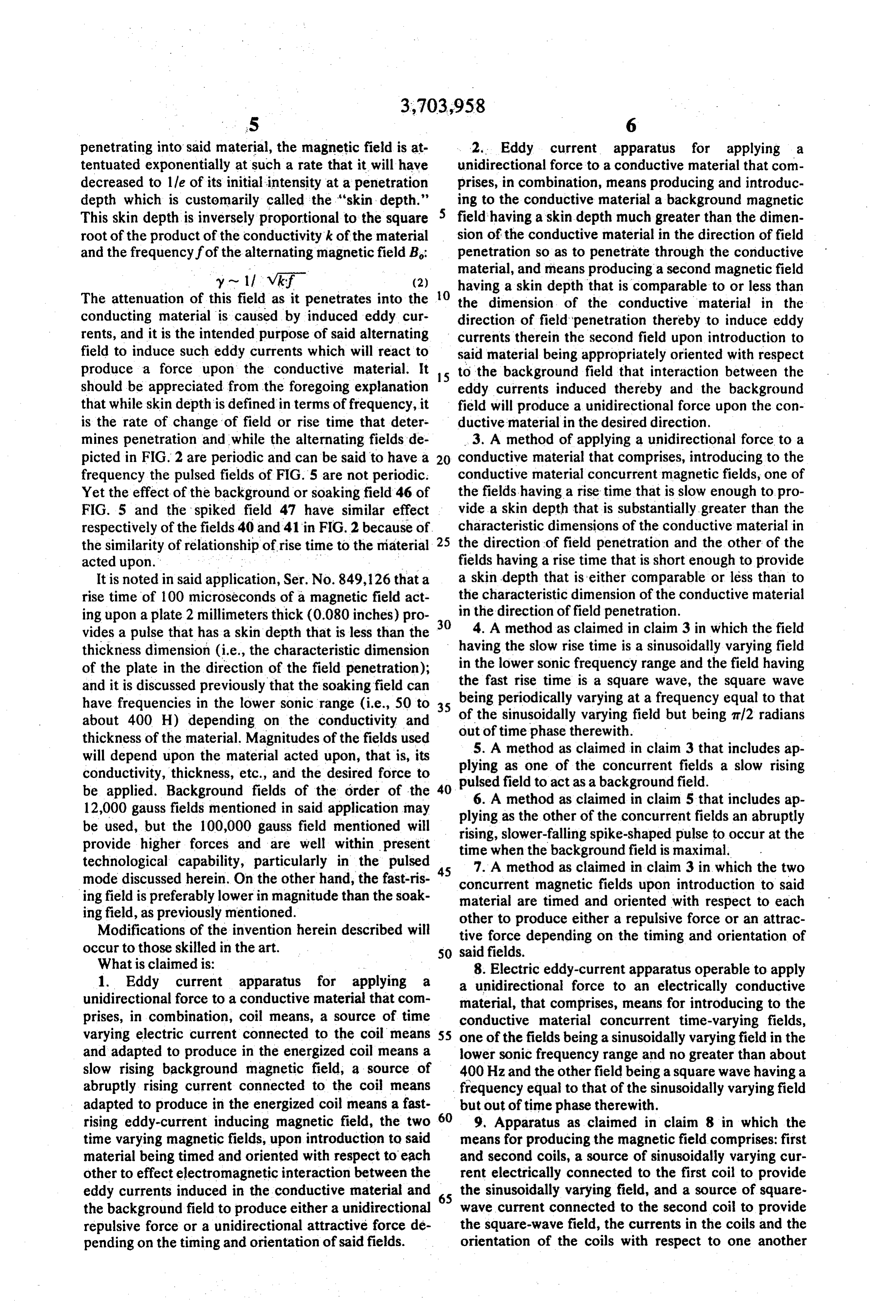
penetrating into said material, the magnetic field is at 2. Eddy current apparatus for applying a tentuated exponentially at such a rate that it will have unidirectional force to a conductive material that com decreased to lle of its initial intensity at a penetration prises, in combination, means producing and introduc depth which is customarily called the "skin depth." ing to the conductive material a background magnetic This skin depth is inversely proportional to the square field having a skin depth much greater than the dimen root of the product of the conductivity k of the material sion of the conductive material in the direction of field and the frequency fof the alternating magnetic field B. penetration so as to penetrate through the conductive material, and means producing a second magnetic field y ~ 11 vkf (2) O having a skin depth that is comparable to or less than The attenuation of this field as it penetrates into the the dimension of the conductive material in the conducting material is caused by induced eddy cur direction of field penetration thereby to induce eddy rents, and it is the intended purpose of said alternating currents therein the second field upon introduction to field to induce such eddy currents which will react to said material being appropriately oriented with respect produce a force upon the conductive material. It to the background field that interaction between the should be appreciated from the foregoing explanation eddy currents induced thereby and the background that while skin depthis defined in terms of frequency, it field will produce a unidirectional force upon the con is the rate of change of field or rise time that deter ductive material in the desired direction. mines penetration and while the alternating fields de 3. A method of applying a unidirectional force to a picted in FIG. 2 are periodic and can be said to have a 20 conductive material that comprises, introducing to the frequency the pulsed fields of FIG.5 are not periodic. conductive material concurrent magnetic fields, one of Yet the effect of the background or soakingfield 46 of the fields having a rise time that is slow enough to pro FIG. 5 and the spiked field 47 have similar effect vide a skin depth that is substantially greater than the respectively of the fields 40 and 41 in FIG.2 because of characteristic dimensions of the conductive material in the similarity of relationship of rise time to the material 25 the direction of field penetration and the other of the acted upon. . . . .. fields having a rise time that is short enough to provide It is noted in said application, Ser. No. 849,126 that a a skin depth that is either comparable or less than to rise time of 100 microseconds of a magnetic field act the characteristic dimension of the conductive material ing upon a plate 2 millimeters thick (0.080 inches) pro 30 in 4.theAdirection of field penetration. vides a pulse that has a skin depth that is less than the having method as claimed in claim 3 in which the field the slow rise time is a sinusoidally varying field thickness dimension (i.e., the characteristic dimension of the plate in the direction of the field penetration); in the lower sonic frequency range and the field having and it is discussed previously that the soaking field can the being fast rise time is a square wave, the square wave periodically varying at a frequency equal to that have frequencies in the lower sonic range (i.e., 50 to 35 about 400 H) depending on the conductivity and of the sinusoidally varying field but being ti2 radians thickness of the material. Magnitudes of the fields used out of time phase therewith. will depend upon the material acted upon, that is, its 5. A method as claimed in claim 3 that includes ap conductivity, thickness, etc., and the desired force to plying as one of the concurrent fields a slow rising be applied. Background fields of the order of the 40 pulsed field to act as a background field. 6. A method as claimed in claim 5 that includes ap 12,000 gauss fields mentioned in said application may plying as the other of the concurrent fields an abruptly be used, but the 100,000 gauss field mentioned will rising, slower-falling spike-shaped pulse to occur at the provide higher forces and are well within present time when the background field is maximal. technological capability, particularly in the pulsed 45 7. A method as claimed in claim 3 in which the two mode discussed herein. On the other hand, the fast-ris ing field is preferably lower in magnitude than the soak concurrent material are magnetic fields upon introduction to said timed and oriented with respect to each ing field, as previously mentioned. other to produce either a repulsive force or an attrac Modifications of the invention herein described will tive force depending on the timing and orientation of occur to those skilled in the art. 50 said fields.
What is claimed is: 8. Electric eddy-current apparatus operable to apply 1. Eddy current apparatus for applying a a unidirectional force to an electrically conductive unidirectional force to a conductive material that com material, that comprises, means for introducing to the prises, in combination, coil means, a source of time conductive material concurrent time-varying fields, varying electric current connected to the coil means 55 one of the fields being a sinusoidally varying field in the and adapted to produce in the energized coil means a lower sonic frequency range and no greater than about slow rising background magnetic field, a source of 400 Hz and the other field being a square wave having a abruptly rising current connected to the coil means frequency equal to that of the sinusoidally varying field adapted to produce in the energized coil means a fast but out of time phase therewith.
rising eddy-current inducing magnetic field, the two 60 9, Apparatus as claimed in claim 8 in which the time varying magnetic fields, upon introduction to said means for producing the magnetic field comprises: first material being timed and oriented with respect to each and second coils, a source of sinusoidally varying cur other to effect electromagnetic interaction between the rent electrically connected to the first coil to provide eddy currents induced in the conductive material and 65 the sinusoidally varying field, and a source of square the background field to produce either a unidirectional wave current connected to the second coil to provide repulsive force or a unidirectional attractive force de the square-wave field, the currents in the coils and the pending on the timing and orientation of said fields. orientation of the coils with respect to one another
Page 7
being such that either a repulsive force or an attractive prises, in combination, means for producing and in force can be applied to said material depending upon troducing to the material a background magnetic field the timing and orientation of the magnetic fields adapted to penetrate through the magnetic material, produced by the electrically energized coils. and means for producing and introducing to the con 10. Apparatus as claimed in claim 9 in which the ductive material another magnetic field having a skin square wave field is n/2 radians out of time phase with depth that is comparable to or less than the dimension the sinusoidally varying field. of the conductive material in the direction of field 11. A method of applying a unidirectional force to a penetration to induce eddy currents within the material conductive material, that comprises, establishing which interact electromagnetically with the within a region of the conductive material a 10 background field to produce a net force on the conduc background magnetic field, the background field hav tive material, the magnetic fields being oriented with ing a skin depth that is much greater than the dimen respect to each other to effect interaction between the sion of the conductive material in the direction of field penetration, and introducing to said region a second, backgrounda field and the induced eddy currents so as fast-rising and slow-falling,or slow-rising and fast 5 to produce unidirectional forcc in a desircd direction. 13. Eddy current apparatus as claimed in claim 12 in falling single pulse or repetitively pulsed magnetic field, which the means for producing and introducing the the skin depth corresponding to the fast rise or fast fall eddy-current respectively being comparable to or less than said the conductiveinducing field produces and introduces to dimension and the skin depth corresponding to the in FIG. 5 of the material drawing a spike-shaped pulse as shown hereof or a series of pulses like slow fall or slow rise respectively being large compared 20 said spike-shaped pulse.
to said dimension, thereby to induce eddy currents 14. Eddy current apparatus as claimed in claim 12 in within the conductive material which interact elec tromagnetically with the background field to produce a which the means for producing and introducing the net force on the conductive material, the fields being eddy-current inducing field produces and introduces to oriented with respect to each other so as to produce a 25 the conductive material a pulse whose rise time differs force in a desired direction. substantially from its fall time thereby to produce said 12. Eddy current apparatus for applying a unidirectional force.
unidirectional force to a conductive material that com k k k k k
Page 8
UNITED STATES PATENT OFFICE
CERTIFICATE OF CORRECTION
. Patent No. 3,703,958 - - Dated - Novemb G 28 l972 Inventor(s). Henry H. Kolm .. . . It is certified that error appears in the above-identified patent and that said Letters Patent, are hereby corrected as shown below:
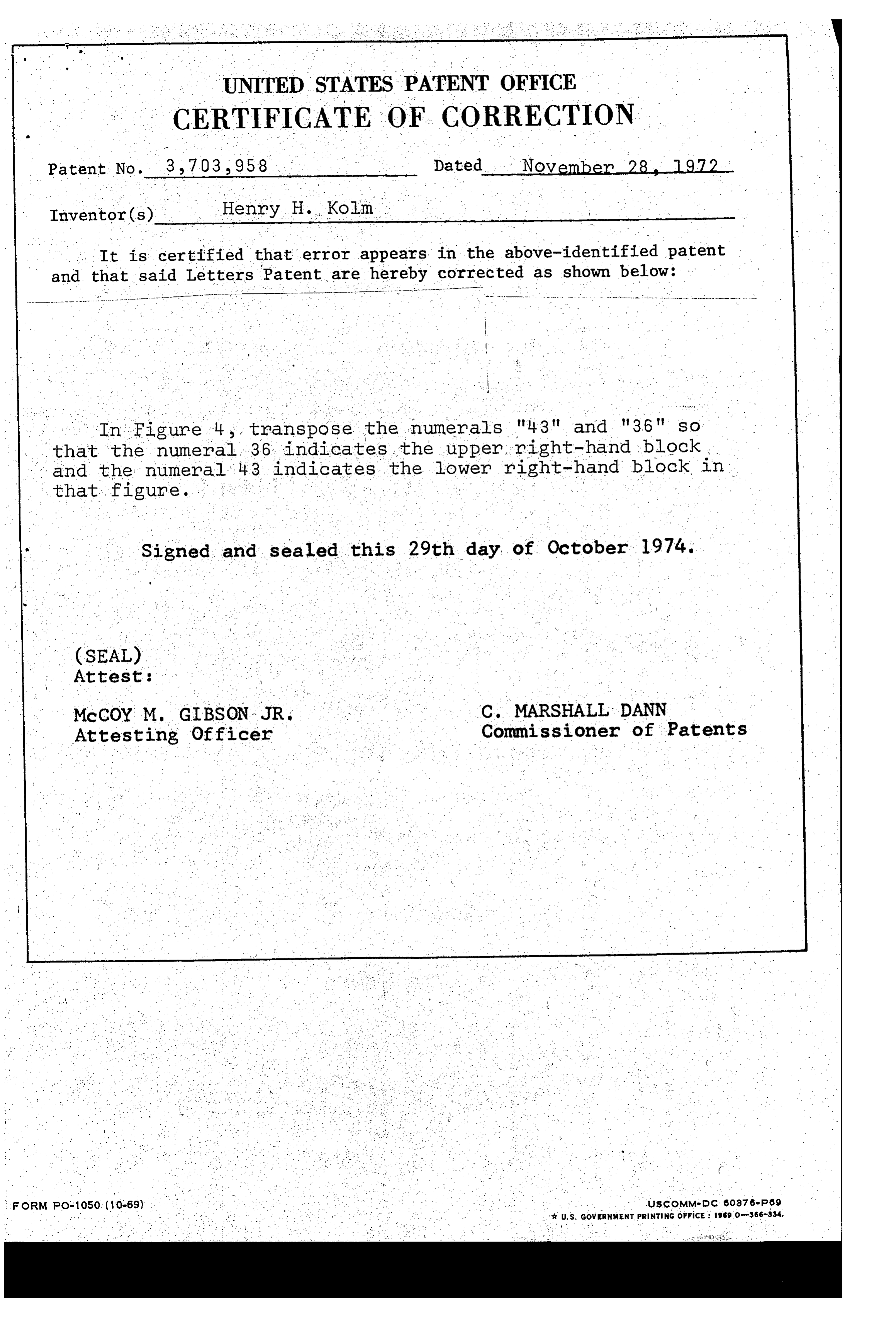
In Figure 4, transpose the numerals "43" and "36" SO that the numeral 36 indicates the upper, right-hand block and the numeral 43 indicates the lower right-hand block in
Signed and sealed this 29th day of October 1974.
(SEAL)
McCOY M. GIBSON JR.
Attesting Officer
MARSHALL DANN
of Patents
ForM. PO-1050 (10-69) . . . . . . . . ." uscoMM-DC 60376-P69 . . . .. . . . . . .. # U.S. Gov ERNMENT PRINTING of FicE: 1969 o-366-334,
Page 9
UNITED STATES PATENT OFFICE
CERTIFICATE OF CORRECTION
Patent No. 32.703, 958 Dated November 28, 1972 - Inventor(s) Henry H. Kolm
It is certified that error appears in the above-identified patent and that said Letters Patent, are hereby corrected as shown below:
In Figure 4, , transpose the numerals "4:3" and "36" so that the numeral 36 indicates the upper right-hand block and the numeral 43 indicates the lower right-hand block in that figure. - - Signed and sealed this 29th day of October 1974.
(SEAL)
Attest:
McCOY M. GIBSON, JR. C. MARSHALL DANN Attesting Officer .. . Commissioner of Patents orM Po-1050 (10-69) - UscoMMsid c 60376ep69 - & U.S. GoweRNMENT PRENTING office: 1969 o-366-334,
Provenance
- Collection
- Cited prior art
- Original PDF
- patentimages.storage.googleapis.com →
- Filed
- 1969-08-11
- Pages
- 9
- Method
- pdftotext (the PDF's own text layer) + pdftoppm 300dpi page scans
- Source
- Google Patents bibliographic record
- Granted
- 1972-11-28
- Inventors
- Henry H Kolm; Massachusetts Institute of Technology
- Transcribed from
- patentimages.storage.googleapis.com →