patent · US4054176
Multiple-completion geothermal energy production systems
18 October 1977
Page 1 — bibliographic record
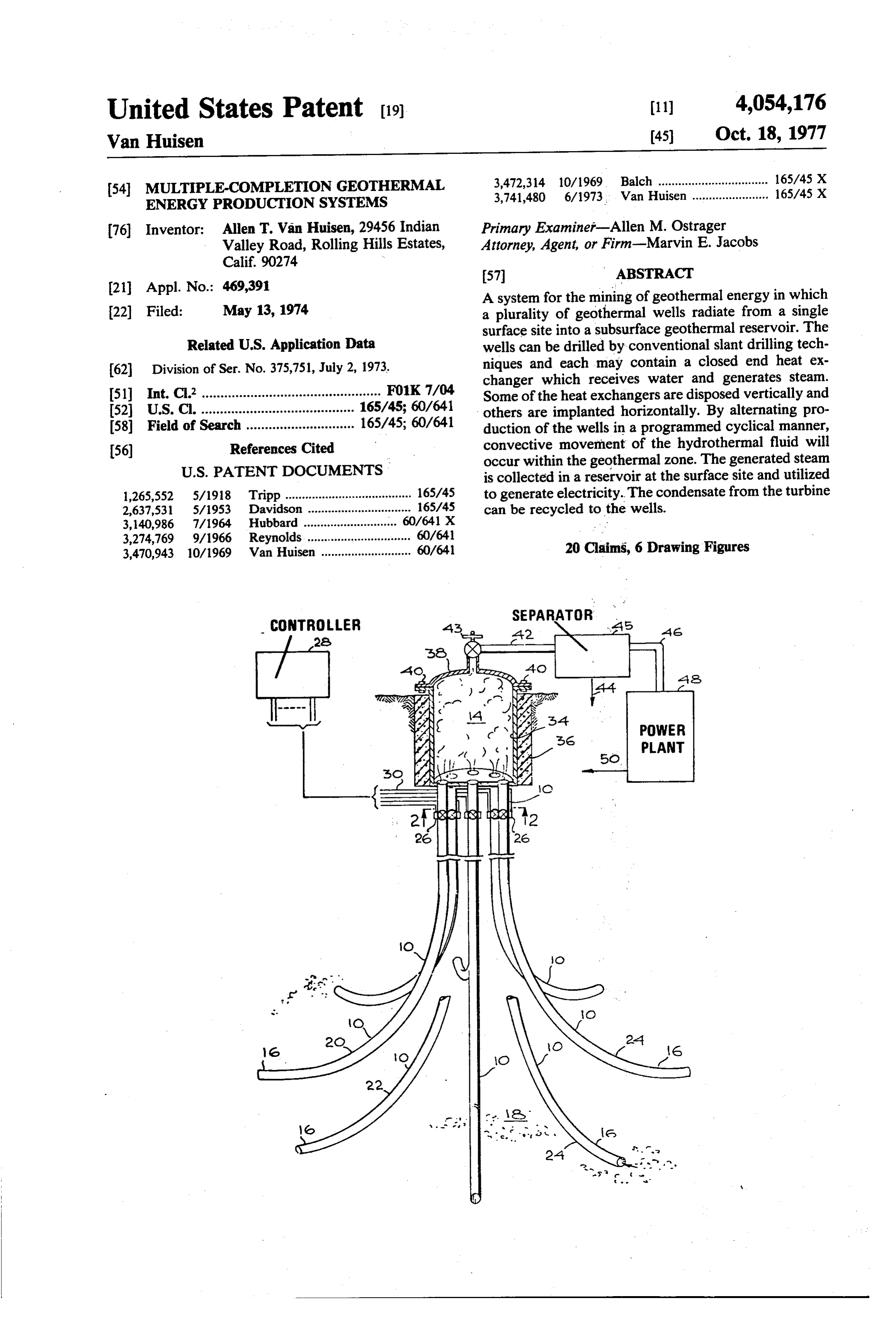
United States Patent (19) 11) 4,054,176 Van Huisen (45) Oct. 18, 1977
54 MULTIPLE-COMPLETION GEOTHERMAL 3,472,314 10/1969 Balch ................................. 165/45 X ENERGY PRODUCTION SYSTEMS 3,741,480 6/1973. Van Huisen - - - - -- -- - - - - - - - 165/45 X
76 Inventor: Allen T. Van Huisen, 29456 Indian Primary Examiner-Allen M. Ostrager Valley Road, Rolling Hills Estates, Attorney, Agent, or Firm-Marvin E. Jacobs
(21) Appl. No.: 469,391 57 ABSTRACT A system for the mining of geothermal energy in which 22) Filed: May 13, 1974 a plurality of geothermal wells radiate from a single surface site into a subsurface geothermal reservoir. The
Related U.S. Application Data wells can be drilled by conventional slant drilling tech 62 Division of Ser. No. 375,751, July 2, 1973. niques and each may contain a closed end heat ex changer which receives water and generates steam.
51) Int. C.’................................................ F01K 7/04 Some of the heat exchangers are disposed vertically and (52) U.S. C. ......................................... 165/45; 60/641 others are implanted horizontally. By alternating pro 58) Field of Search ............................. 165/45; 60/641 duction of the wells in a programmed cyclical manner, (56) References Cited convective movement of the hydrothermal fluid will
is collected in a reservoir at the surface site and utilized 1,265,552 5/1918 Tripp ...................................... 165/45 to generate electricity. The condensate from the turbine 2,637,531 5/1953 Davidson ............................... 165/45 can be recycled to the wells. 3, 140,986 7/1964 Hubbard ....... . . 60/641 X 3,274,769 9/1966 Reynolds................................ 60/641 3,470,943 10/1969 Van Huisen ........................... 60/641 20 Claims, 6 Drawing Figures
Page 2
Drawing sheet — no readable text.
Page 3
Drawing sheet — no readable text.
Page 4
Drawing sheet — no readable text.
Page 5
MULTIPLE-COMPLETON GEOTHERMAL
tions suggests the existence of seven or eight similar
ENERGY PRODUCTION SYSTEMS brine pools between Niland and the pool at Cerro Prieto in Mexico. In all, the power generating potential from
CROSS REFERENCE TO RELATED geothermal energy in the Imperial Valley is estimated APPLICATION to be as high as 30,000 MW. Successful exploitation of . this potential by conventional direct thermal mining
This application is a division of application Ser. No. methods would require either selective use of the lower 375,751, filed July 2, 1973. salinity brine or disposal of vast amounts of salt and BACKGROUND OF THE INVENTION concentrated salt bitterns. Geothermal energy repre 10 sents a clean, pollution free alternative to fossil fuel 1. Field of the Invention energy sources and does not entail the hazards or the The present invention relates to utilization of geother environmentally unacceptable aspects of nuclear pro mal energy and more particularly to an improved sys duced power.
tem for maximizing the transfer of geothermal energy The problems inherent in the conventional direct from a subsurface zone to the surface for utilization. 15 thermal mining approaches are avoided by use of the 2. Description of the Prior Art
There exists, essentially untapped, massive quantities downhole heat exchanger disclosed in U.S. Pat. No. 3,470,943 since the geothermal brines remain in the pool of heat available from magma which has migrated to and heat is extracted by in situ circulation of a clean, zones close to the surface. Such conditions exist in large stable, secondary heat transfer fluid inside the down regions of the United States and in other locations 20 hole heat exchanger which is placed at the lower part of throughout the world such as in Italy, New Zealand the casing within the geothermal zone. Thus, the down and Japan. Frequently, tectonic activity has produced hole heat exchanger provides a means for utilizing the fault lines which have permitted deep, subsurface wa heat contained in the brine pools by extracting only the ters to come in contact with magmatic rocks and return heat energy, leaving the brine recirculating in the un to the surface along fault lines as heated water, or in a 25 derground pool. The advantages are many. few cases as steam. Similarly, tectonic activity below No saline fluids are brought to the surface; hence ancient subsidence areas, more recently overlain, have there are no disposal problems and reinjection wells are resulted in migration of heat into brine pools of varying not required. The reservoir inventory and pressure is salinity which lodged in these sinks. There are some 1.8 undisturbed. Except for extraction of heat, which is million acres in the United States which are designated readily replenishable, nothing has been changed in the as KGRA (Known Geothermal Resource Areas) and reservoir. Subsidence therefore will be avoided by this most of these KGRA are situated in the Wester states. method.
The only operating geothermal plants in the United Since the interior of the casing is contacted only by States are those operating at The Geysers, Sonoma, pure fluids, no corrosion or scaling will occur inter California, and others are formulating plants for geo 35 nally. The outside of the casing is in contact with the thermal power development in the Imperial Valley of reservoir aquifer but the brine is at a pressure which California. The plants in operation in the United States does not allow the dissolved salts to precipitate. Hence, and Italy rely on direct thermal fluid mining methods. there is no abrasive action from the solids as in a flowing Such methods have entailed serious problems due to the well. The convective currents within the aquifer are high salinity of the steam causing cavitation, abrasion, 40 expected to be of insufficient velocity to result in abra scaling and corrosion of the equipment over short inter sion. The low velocity should also promote the reten vals. Moreover, geological prospecting techniques are tion of a thin, passive coating of corrosion products not very accurate and if a dry well results or a well with which inhibit further corrosion. insufficient steam pressure the venture is a total loss. The downhole heat exchanger system represents a Drilling of adjacent thermal direct fluid recovery wells 45 truly non-polluting source of energy in that no pollution entails the risk of lowering the bottom hole pressure of products are permitted to reach the surface. However, the whole field. It is estimated that a brine pool exists in the energy capacity of a single well is not sufficient to the Niland area of the Imperial Valley of California justify the installation and operation of a generation which occupies an area of 25 square miles. About a plant. Therefore, multiple wells are required to develop dozen geothermal wells have been drilled in the area, 50 sufficient steam to operate the turbine generator. This which produce as much as a million pounds per hour of requires the utilization of a greater area of the surface brine per well for sustained periods. Flashing this brine for drilling the multiple wells and a greater investment would produce about 200,000 pounds per hour of steam cost to drill the well at each site. Furthermore, the which in turn could produce about 10,000 kW of elec separate location of the multiple wells requires water tric power per well. 55 injection lines running to each well site and steam gath However, because of the high salinity of the brines, ering lines running from each site to the generating all attempts to utilize these brines have been unsuccess ful. Since the discovery of these wells, several compa plant. All of this involves capital investment and entails heat loss each time the stream or water is moved.
nies have spend millions of dollars trying to extract chemicals and generate power from the brines. Neither 60 SUMMARY OF THE INVENTION operation has been commercially successful because of The multiple-completion geothermal system of the the high operating costs and associated material costs invention generally includes a plurality of geothermal necessary to withstand the corrosive and erosive envi wells, each having a first end converging toward and ronment and to dispose of the salt and concentrated salt meeting at a first point and having a second end diverg bitterns. 65 ing from said point and terminating in a geothermal Further to the South in Mexico, another brine pool zone, each second end being spaced from any other exists of a size comparable to the Niland pool. The brine second end of said geothermal wells. This system fur is lower in salinity in this pool. Exploratory investiga ther includes a reservoir located at said first point re
Page 6
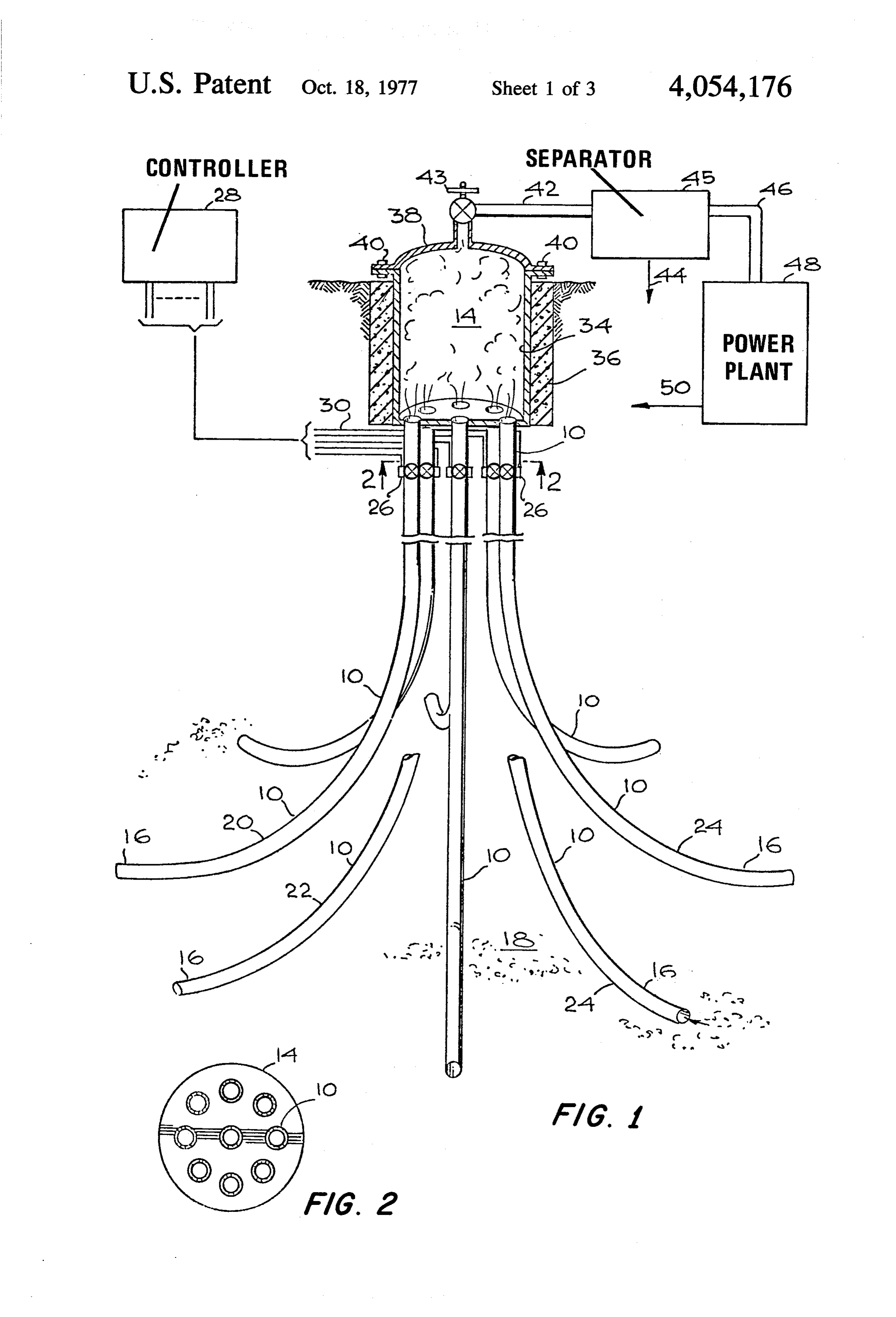
3 mined pattern such as those of wells 20 and 22 which ceiving heated geothermal fluid from the second end of each well, outlet means connected to said reservoir for are spaced vertically from each and the ends of wells 20 conducting the heated geothermal fluid in turn to sepa andEach 24 which are spaced horizontally from each other. well contains a valve 26, suitably a servo-con ration means and energy conversion means. The system 5 trolled valve in accordance with the invention also may include con be individuallysuch that production from each well can controlled, suitably by a time sequencer trol means for sequentially activating production from controller 28 which activates or deactivates each valve each of the plurality of wells in sequence to promote 26 according to a predetermined program by sending movement of hydrothermal fluids within the geother signals through lines 30. The sequential production of mal zone.
Depending on the condition of the geothermal zone, pattern, will promote convective movementin of 10 wells 10, especially by rotating production a circular the system may require further structure. In a wet geo drothermal fluid 32 within the geothermal zone the 18,
and thermal zone, the fluid will operate as a carrier for the thus, increase heat transfer and recovery and decrease heat energy to deliver it to the surface under pressure. the
In the case of a dry geothermal zone or one containing 15 24 ofpossibility the portion of scale forming on the external surface of the well casings within the zone 18.
a molten brine pool with insufficient pressure, the im The geothermal, heated fluid recovered from the plantation of closed and heat exchangers at the ends of wells the wells requires means for conducting heat exchange may becollects located within the reservoir 14. The reservoir on the surface but is preferably recessed fluid to the heat exchangers which may be connected to below the surface to take advantage of the insulating the turbine to return the condensate to the heat ex changer in a closed cycle loop. Heat transfer to the heat 20 and warming effects of the subsurface strata. The reser voir is preferably a steel vessel 34 bounded by a con exchanger in a dry geothermal zone may also be en crete layer 36 and includes a removable lid 38 secured hanced by injection of water into the zone external to by bolts 40.
the heat exchanger to create hot fluid to increase the The collected steam is transferred through conduit 42 transfer rate of heat to the outside surface of the heat exchanger. 25 containing a pressure regulating valve 43 to a separator It is apparent that the system of the invention mini 45. and
Condensate and solids are removed through line 44 the steam is delivered through line 46 to the power mizes the amount of surface area needed for access to the subsurface geothermal zone, the amount of surface engine48.orThe plant
power plant can be a direct prime mover turbine generator. Condensate is removed area needed for collection and conversion of the geo 30 through line 50 and may be recovered or recycled to th thermal fluid to electrical energy and minimizes the wells.
external piping conduits and energy loss that would be Geothermal fields are classified according to their entailed in the separate spaced drilling of multiple wells production of hot water, hot water and steam, or dry to tap and mine the geothermal energy in a known steam. The system of FIG. 1 can be used for the recov geothermal resource area. The system of the invention 35 ery of geothermal heat also includes provision for controlled collection of the fields. Hot water fields values from all of these types of typically produce temperatures energy and in a manner to promote convection and between 60' C and 100 C, with gradients of 30' C/km movement of the hydrothermal fluids to increase the to 70 C/km. Because of the low enthalpy, hot water rate of energy recovery and to decrease the possibility of scaling and fouling the external portions of the wells fields are not now being used to generate electricity. being utilized for collection and transfer of heat. 40 They are being used instead for space heating and air These and many other objects and attendant advan conditioning. For electrical production most geother tages of the invention will become apparent as the in tures greater than 100bothC. water mal fields produce
The and steam at tempera highest temperature field vention becomes readily understood by reference to the in use to date is at Cerro Prieto, Mexico, following detailed description when considered in con 45 peratures have been measured up to 380 atC.which tem Similarly, junction with the accompanying drawings. the dry steam fields in commercial use have tempera BRIEF DESCRIPTION OF THE DRAWINGS tures at 210 C (The Geysers, U.S.) to 260' C (Lar FIG. 1 is a perspective view of a multiple-completion derello, Italy).
geothermal mining system in accordance with the in 50 ing basic geologicalfields
The geothermal in production have the follow characteristics:
vention; 1. A source of heat . .' FIG. 2 is a sectional view taken along line 2-2 of In general, magmatic intrusions at shallow depths of 7
FIG. 3 is a schematic view of a further embodiment of to 15 km provide a heat source at a temperature about a mining system in accordance with the invention; 100 C, typically from 200 C to 400 C. FIG. 4 is a top enlarged view of the system of FIG. 3; 55 2. A source of water . FIG. 5 is an enlarged cross-sectional view of a closed water Commercial wells produce more than 20 tons/hour of end heat exchanger; and and steam. The best well, located in the Cerro FIG. 6 is a plan view of a geothermal mining system Prieto field, produces 350 tons/hour. The water is be in accordance with the invention. lieved to come from surface sources rather than being 60 magmatic water. Therefore, it is probably replenishable
DESCRIPTION OF THE PREFERRED at a rate determined by pressure, permeability, source EMBODIMENTS availability and other factors. Reinjection may be uti Referring now to FIGS. 1 and 2, the system includes lized towater replenish the source and dispose of unwanted a plurality of geothermal wells 10 each having a first, 65 surface
such as condensate from the turbine.
permeable rock aquifer open, upper end 12 converging toward and meeting Almost any permeable rock can serve as an aquifer within a surface point bounded by a closed reservor 14. such as deltaic sand, volcanic turf, base salt flows, ig The lower end 16 of each well terminates within a geo nimbrite, greywacke, carbonate volcanics and lime thermal zone 18. The ends are positioned in a predeter
Page 7
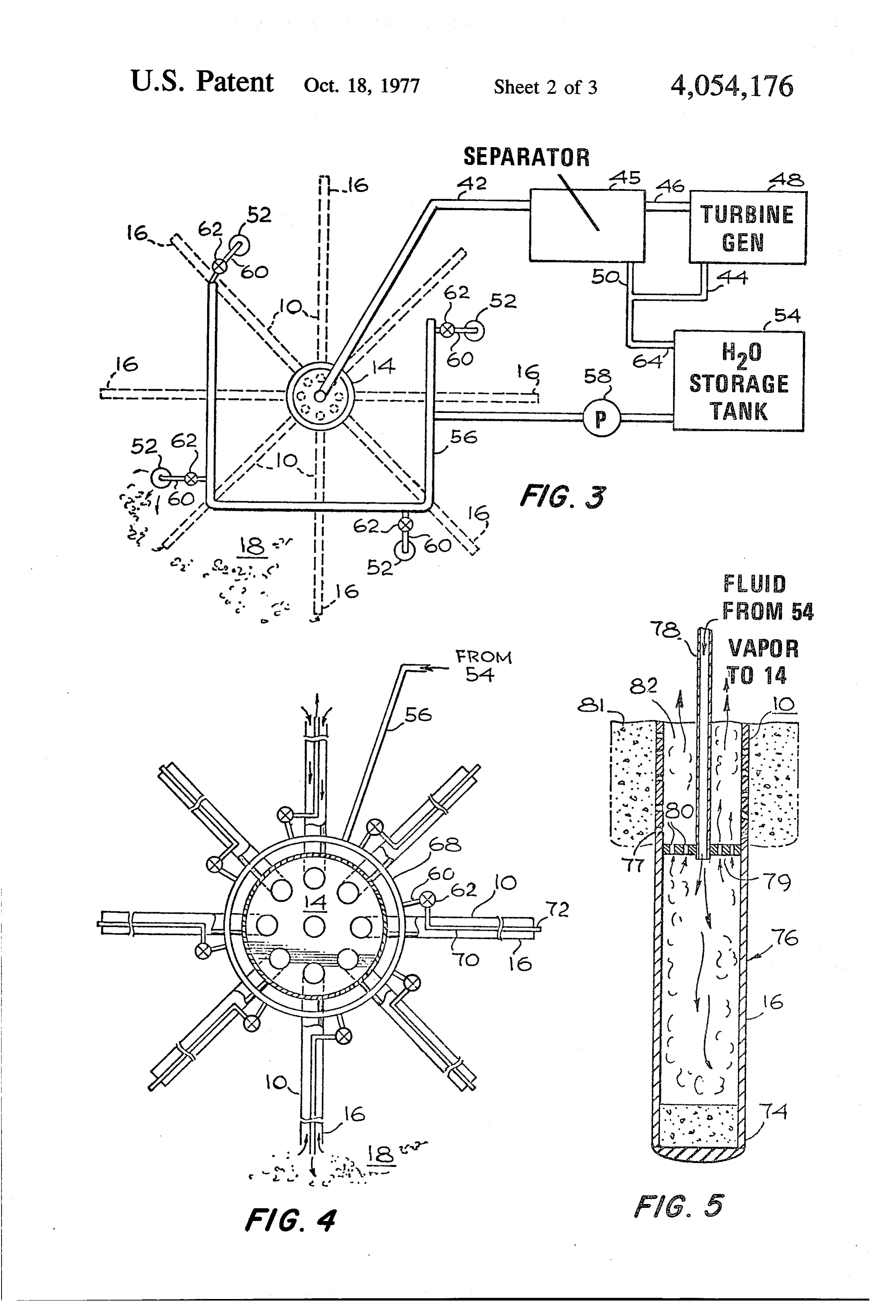
stone. Convection currents through the rock are be level of the ends 16 of the geothermal wells 10, so as to lieved to be the primary heat transfer mechanism be form a rising body of pressurized, heated hydrothermal tween the magma and upper levels of the aquifer; these fluid. The water injection wells 52 can be supplied sepa can be reached by drilling. Pressures in the aquifer may rately with water, or as illustrated can be supplied from be as high as 2000 psior more. Both thermal conductiv a central storage tank 54 and pumped by means of pump ity and permeability are critical parameters which limit 58 through line 36 to each of the injection wells 52. the energy production of the well. The branch input conduit 60 to each injection well 52 4. A cap rock contains a valve 62 so that production may be cycled to A rock layer of low permeability is required above induce movement of thihydrothermal fluid. The hydro the aquifer to limit the heat transfer by convection. The 10 thermal fluid enters the ends 16 of the recovery wells 10, collects in reservoir 14 and is transferred through heat loss transfer through the cap rock to the surface line 42 to the separator 45 and turbine generator 48. primarily by convection is very low; this allows the system to remain hot. Many systems are believed to be Condensate in lines 50 and 44 is recycled through line self-sealing due to mineral, primarily silica, depositions 64 to the storage tank 54 for reinjection in the zone 18 of the hot water flashed and cold near the surface. 15 through wells 52.
All of these geothermal aquifers can be mined by A preferred injection-recovery system is illustrated in direct thermal mining methods in the system of the recovery FIG. 4. In this system, water injection is internal of the invention which will provide the same advantage of well casing. This again simplifies the installa collection of the thermal fluid at a single point, thus 20 tion, minimizes surface installation of long lengths of reducing capital investment and well installation costs pipes and totally obviates the necessity of separate in and the surface area needed for converting the fluid to jection wells. A further incidental benefit is that the mechanical or electrical energy. However, for the rea decending water is heated by the ascending geothermal sons previously discussed, the wet geothermal areas can fluid. As shown in the drawings, the delivery pipe 56 is more efficiently be mined by the downhole heat ex connected to a single distribution ring 68 which may changer relation of the multiple-completion system of 25 surround the outside of the casing for recovery wells 10 this invention. Dry geothermal areas may also be mined or may be positioned on the inside surface of the cas by either method. A man-made aquifer may be devel ings. The branch inlets 60 again contain a valve 62. The oped by explosion-stimulated methods. If the hole is hot inlets 60 sealingly penetrate the casing of each well 10 and dry and not fractured, a large aquifer could be and are connected to a water injection pipe 70. The end developed by hydrofracturing alone or in combination 30 72 of the water injection pipe preferably extends past with explosive induced means. The downhole heat ex geothermal the end 16 of the casing and into the porous or fractured changer offers the opportunity to recover heat from the zone 18 at a depth below the ends 16 of the dry and hot geothermal area without the need to inject casing 10.
water to the zone to create a hydrothermal fluid. All of the hydrothermal systems suffer from the com If the system is hot, dry and fractured, water can be 35 mon disadvantage of recovery of a saline hydrothermal introduced from the surface internal of the well casing posal.fluid with the attendant problems of scaling and dis or external of the well casing and the resultant steam heat exchanger For the reasons discussed above, the downhole collected through the annulus of the well removed and variant of the multiple-completion sys harnessed to produce energy. If the system is hot, dry tem is far preferable. Such a system is shown in FIG. 5. and unfractured, it may be utilized as such with the 40 In this system, the lower end 16 of each recovery well downhole heat exchanger to produce steam by indirect cement contains a plug 74 such as a metal-rubber layer over a heat exchange methods or hydrofracturing and en layer. The terminal portion of the casing of each hancement can be practiced through additional thermal injection pipe or well contains forms a closed heat exchanger 76. An 78 delivers heat exchange fluid to the top stress fracturing or by the use of high explosive or nu clear devices to fracture large quantities of hot rock as 45 70 of the heat exchanger which is heated to form vapor described in my copending application Ser. No. 99,898, therein. The vapor leaves through perforations 80 in the filed Dec. 21, 1970, which disclosed a system for pro top 79 and rises through the annular space in each cas ducing a rubble cone activity in a hot, dry rock geother ing and collects within the reservoir 14 and after separa mal zone, the disclosure of which is incorporated herein tion in separator 45 and conversion to electricity in turbine-generator 48 is recycled to storage tank 54 for
Referring again to FIGS. 1 and 2, in a system for reinjection as previously described. mining wet geothermal energy, the separator 45 would The borehole is preferably cased with a metal casing be a flash unit and the wet steam is delivered to the which is in turn cased with a layer of concrete 81. For power plant 48 while the separated salts and condensate purposes of heat conduction to the heat exchanger 76, it are removed through line 44. The salts may be sepa 55 isposed preferred that the metal surface 24 be directly ex to the hydrothermal fluid. Referring again to rated into commercial salts for sale, may be concen trated and disposed or may be reinjected into the zone. FIG. 5, this installation is effected by lining the bore In a system in which fairly dry steam is directly recov hole with a metal casing 85. The casing is perforated at ered, separation of solids may be required in a cyclone 77 at the location corresponding to the top of the heat separator to minimize cavitation of the turbine blades. exchanger 76.
Hydrothermal injection systems for mining a dry field The casing is then temporarily plugged directly below are illustrated in FIGS. 3 and 4. Referring now to FIG. temporary the perforations 77. Cement is delivered to the 3, an external water injection system is illustrated in plug area and squeezed through the perfora which water is injected into the dry, porous geothermal tions 77 to form a plug 81 in the annular area outside the zone 18 by means of a plurality of water injection wells 65 casing 85. The upper casing 85 is then cased in cement. 52. The wells are spaced about the periphery of the The temporary plug is then drilled out and the lower geothermal zone being mined and extend from the sur plug 74 is inserted and the top 79 of the heat exchanger face to the zone 18 and preferably extend below the is installed.
Page 8
The closed-cycle system for extraction of heat from a On the basis of these criteria, the outer casing size of geothermal zone provides a choice of heat exchange 13.375 inches O.D. is preferred since for the depth and fluids such as isobutane or water. Demineralized water temperature specified in the heat recovery zones this is is the fluid of choice since its thermal and physical prop about the largest size casing (heat transfer surface) erties permit high heat transfer capabilities, and steam which provides an economic weight (strength) per unit vapor is directly usable in conventional and economi length required to withstand the internal and collapsing cally available condensing steam turbines. Condensate pressure encountered as well as the problems associated is easily handled for return to the heat recovery zone. with offset drilling. The inner pipe will be selected to Also, demineralized water can be readily produced in satisfy the overall system flow hydrodynamic require conventional and economically available equipment 10 and all of its physical properties and handling tech ments. It is expected that long life would be experienced with heavy wall carbon steel casings in the above condi niques are well known. tions.
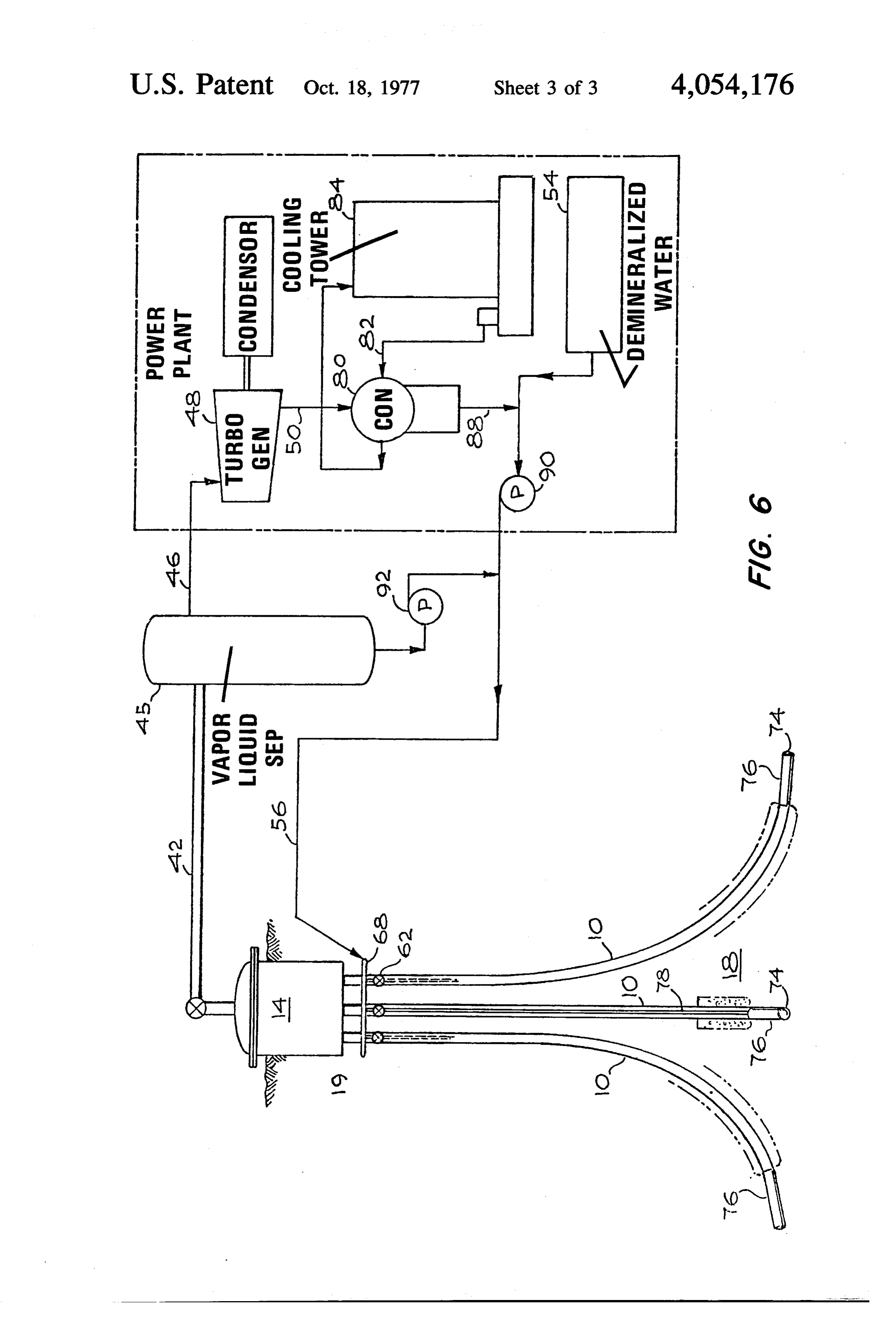
A schematic illustration of a more detailed embodi The same casing and cementing practices employed ment of the downhole heat exchanger is illustrated in for other geothermal wells can be followed, the only FIG. 6. FIG. 6 has been designed for the recovery of 15 difference being the closed end of the 13 inch casing sufficient heat energy for the production of 50 mega which acts as a shell of the downhole heat exchanger. A watts (at the generator terminals) of electric power. further advantage of the directional slant drilling multi Referring now to FIG. 6, the system includes a plural ple-completion ity of downhole heat exchanger recovery wells 10 hav vides greater heatsystem of the invention is that it pro exchange area within the zone of heat ing a plugged end 74 within a geothermal zone 18. The 20 collection, upper ends 19 of the wells 10 converge to and meet in a to producethus a reducing the amount of wells necessary given amount of power. By slant drilling reservoir 14. The steam output from the reservoir is through the 3,000 foot to 5,000 foot zone under consid delivered through line 42 to a vapor-liquid separator 45, condensed through line 46 to a turbogenerator 48. The eration, it is estimated that 10 wells must be drilled to provide the desired heat exchange surface area. The low pressure steam from the turbo generator is deliv 25 typical ered through line 50 to a condensor 80 which receives casing requirements will require about 8,000 feet a continuous supply of cold water circulating through of the casing within the zone forming the heat ex circuit 82 containing a cooling tower 84. The conden changer which will be connected to 1800 feet of ce sate from condensor 80 joins line 56 through line 88. mented production casing and then to 50 feet of ce Demineralized water from supply tank 54 and the con 30 mented 20 inch second string which in turn is then densate are pumped by means of power condensate connected to 50 feet of cemented 36 inch conductor pump 90 and preheat condensate pump 92 to the injec casing. The top end 19 of the wells can readily be sepa tion ring 68. rated by 25 to 150 feet and can be located in the surface In this system, the steam is vaporized within the outer zone bounded by a single reservoir 14. casing while it passes through the reservoir geothermal 35 Each well at the bottom should produce steam at 320 heat zone 18. The inner pipe returns the condensate psia at a temperature of 423 F. The rising steam should from the above-ground power plant turbine condenser maintain a pressure at the top after condensing the and vapor-condensate separator down to the well bot down-coming return condensate of 165 psia and a tem tom to complete the heat exchange fluid transport cir perature of 366 F. At the vapor-liquid separator 45 cuit. The inner pipe also serves to preheat the conden such wells will provide 857,000 lbs. per hour vapor and sate up to the boiling thermal equilibrium established 343,000 lbs. per hour of condensate. This vapor has an during operation. The preheating requires vapor con inert pressure of 130 psia and a temperature of 350 F to densation. This condensate is separated from the power provide a heat input to the turbogenerator of 1023 X vapor fluid in a vapor-condensate separator and recy 106Btu/hour and a heat rate of 20,500 Btu/kWh gross at cled. The power vapor is used in a conventional con 45 the generated terminals. This is sufficient to provide 15 densing type vapor turbine in a totally enclosed recycle megawatts at the generated terminals. The condenser system and thus the power fluid is conserved. The returns this vapor as power condensate at a rate of 1714 power vapor turbine has an indirect exhaust vapor con gallons per minute at a temperature of 125 F which denser and condensate recycle pumping system. combines with the preheat condensate at 773 gallons The following calculations for feasibility of the sys 50 per minute to be returned to develop the necessary tem of the invention were based on a heat assumed to steam to power the system.
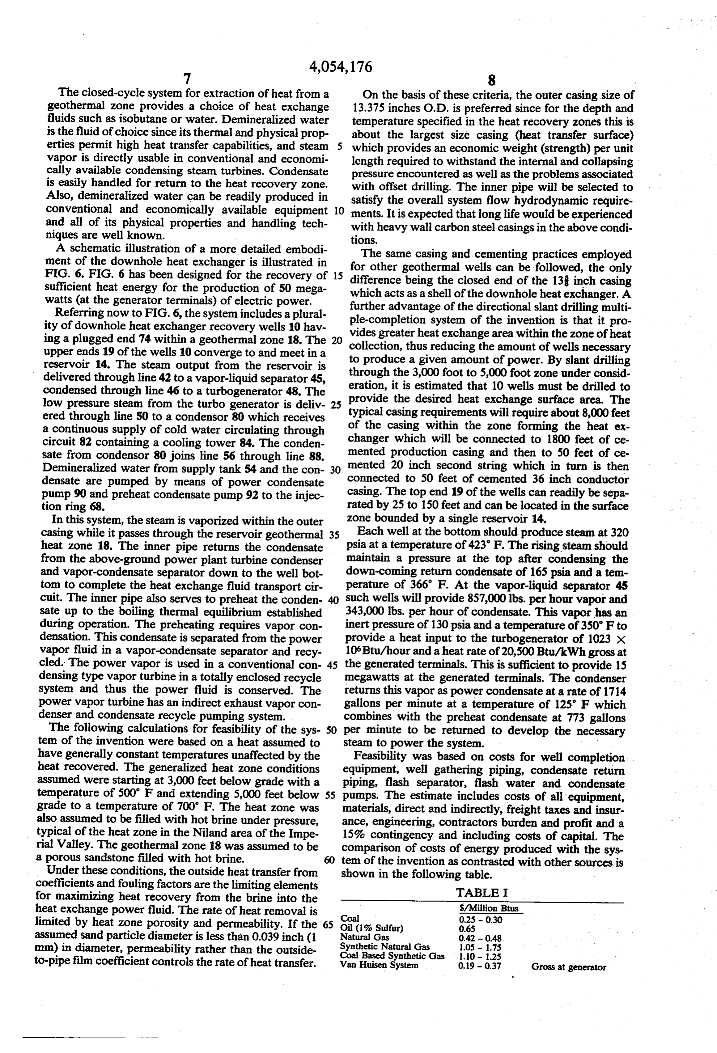
have generally constant temperatures unaffected by the Feasibility was based on costs for well completion heat recovered. The generalized heat zone conditions equipment, well gathering piping, condensate return assumed were starting at 3,000 feet below grade with a piping, flash separator, flash water and condensate temperature of 500 F and extending 5,000 feet below 55 pumps. The estimate includes costs of all equipment, grade to a temperature of 700' F. The heat zone was materials, direct and indirectly, freight taxes and insur also assumed to be filled with hot brine under pressure, ance, engineering, contractors burden and profit and a typical of the heat zone in the Niland area of the Impe 15% contingency and including costs of capital. The rial Valley. The geothermal zone 18 was assumed to be comparison of costs of energy produced with the sys a porous sandstone filled with hot brine. tem of the invention as contrasted with other sources is Under these conditions, the outside heat transfer from shown in the following table.
coefficients and fouling factors are the limiting elements TABLE I for maximizing heat recovery from the brine into the heat exchange power fluid. The rate of heat removal is Coal S/Million Btus
limited by heat zone porosity and permeability. If the Oil (1% Sulfur) 0.65 assumed sand particle diameter is less than 0.039 inch (1 Synthetic
mm) in diameter, permeability rather than the outside Coal Based Synthetic Gas 1.05
to-pipe film coefficient controls the rate of heat transfer. Van Huisen System 0.9 - 0.37 Gross at generator
Page 9
TABLE I-continued 7. A system according to claim 1 in which said geo SMMillion Btus thermal zone is absent geothermal fluid and further terminals including water injection wells extending from the sur
'Adjusted to heat rate equivalent of modern fossil fuel power plant rates of approxi face into said common zone and having lower ends mately 10,000 Btus/kWh. 5 terminating in the vicinity of the second ends of the geothermal wells and pump means for injecting water
Recent pollution regulations regarding maximum into said injection wells.
sulfur content in fuels of 0.3 to 0.5% have placed a 8. A system according to claim 6 in which the second considerable burden on refiners to produce low sulfur end of each of said wells includes a closed heat ex petroleum based fuels. It is estimated that the added 10 changer and a central water delivery pipe is disposed processing may cost as much as $1.50 bbl or $0.24 per within the well and connected to said heat exchanger.
million Btus. Many coals run 3 to 4% sulfur and the 9. A system according to claim 8 in which an annular only practical way to meet pollution standards is to water supply loop is disposed adjacent the first ends of desulfurize the stack gases which is estimated to add as penetrating said heat exchangers and connection means sealingly much as $60–$70 kW in capital investment or 15 said the wall of each heat exchanger connecting $0.09-$0.11 per million Btus. Typical fuel costs in terms loop to each central delivery pipe. of mills/kWh for privately owned utilities as of 1969, separate 10. A system according to claim 9 further including run 3.5 to 6.5 mills/kWh. It is estimated that by 1975 means forvalve means connected to each connection fuel prices will roughly double and utilities will proba said wells. controlling the delivery of water to each of bly be paying 7.0 to 13 mills/kWh for fuel. The energy 20 cost of 1.91 to 3.71 mills/kWh compares vary favorably ond11.ends A system according to claim 1 in which said sec includes a closed end metal heat exchanger with competing fossil fuels for this module of power. having metal walls directly exposed to the geothermal No comparison could be made with nuclear fuel plants ZOC.
since nuclear fuel plants would be uneconomical to 12. A system according to claim 1 in which a plurality build in the range of 50 MW/150 MW. 25 of said heat exchangers are implanted horizontally in It is to be realized that only preferred embodiments of said zone and a plurality are implanted vertically in said the invention have been described and that numerous ZOC.
substitutions, alterations and modifications can readily 13. A system according to claim 1 in which said zone be made by those skilled in the art without departing is at least 3000 feet below the surface and has a tempera from the spirit and scope of the invention as defined in 30 ture of at least 300' F.
the following claims. 14. A system according to claim 1 in which said reser What is claimed is: voir walls are dormed of metal and the side metal walls 1. A system for the recovery of geothermal energy are cased with cement.
comprising: 15. A method of recovering geothermal energy com a closed, steam vapor collection reservoir vessel hav 35 prising the steps of:
ing side walls, a top wall and a bottom wall, said recessing the apertured bottom wall and the side walls side walls and bottom wall being recessed below of a closed, steam vapor collection reservoir vessel the surface of the earth and said bottom wall con below the surface of the earth; taining a plurality of apertures; slant drilling a plurality of geothermal wells, each a plurality of cased geothermal wells, the casings of 40 having a first upper end converging toward said each having a first end converging toward and reservoir vessel and a second lower end disposed sealingly connected to one of the apertures in the within a common, wet geothermal zone; bottom wall of said reservoir and each well casing casing each of said wells;
diverging from said reservoir and having a second connecting each of the upper, first ends of said casings end disposed within a common, wet geothermal to the aperture in the bottom wall of said reservoir zone having a temperature of at least 300 F; 45 vessel;
said second ends being closed and a portion of each inserting a closed end heat exchanger at said second well within the zone and containing the closed end end;
forming a heat exchanger; injecting water into each of said heat exchanger; and supply means for delivering water from the surface to delivering heated water vapor from each exchanger said heat exchanger to form steam vapor therein; to the reservoir.
and 16. A method according to claim 15 in which at least vapor fluid delivery means within each of said wells one of said heat exchangers is implanted horizontally to conduct heated steam vapor fluid from each within said zone and at least one heat exchanger is im planted vertically within said zone.
second end to said reservoir.
2. A system according to claim 1 further including 55 17. A method according to claim 16 further including valve means connected to each of said wells for termi the step of implanting at least one of said heat exchang nating delivery of water to said reservoir. ers at a different horizontal plane within said zone than 3. A system according to claim 2 further including said other heat exchangers.
control means associated with said valve means for 18. A method according to claim 15 in which said cycling production of said well means. heat exchanger has an outer metal shell directly exposed 4. A system according to claim 1 in which at least on to said geothermal zone.
of said common ends terminates in a different horizontal 19. A method according to claim 15 in which said plane within said zone than other of said second ends. zone is dry, and further including the step of injecting water into said zone.
5. A system according to claim 1 in which said wells are lined with a metal casing and a cement outer casing. 65 the20.step A method according to claim 15 further including of inducing convective movement of hydro 6. A system according to claim 5 in which at least a thermal fluid within said zone by cycling production of portion of the metal casing within said zone is not cased heated fluid delivery to said reservoir among said wells. with cement.
Provenance
- Collection
- Cited prior art
- Original PDF
- patentimages.storage.googleapis.com →
- Filed
- 1974-05-13
- Pages
- 9
- Method
- pdftotext (the PDF's own text layer) + pdftoppm 300dpi page scans
- Source
- Google Patents bibliographic record
- Granted
- 1977-10-18
- Inventors
- Allen T. Van Huisen
- Transcribed from
- patentimages.storage.googleapis.com →