patent · US4384569
Solar energy collector/storage system
24 May 1983
Page 1 — bibliographic record
United States Patent (19) 11 4,384,569 Clearman et al. 45 May 24, 1983 54 SOLAR ENERGY COLLECTOR/STORAGE Primary Examiner-Larry Jones SYSTEM Attorney, Agent, or Firm-Donald J. Singer; Jacob N. Erich 76) Inventors: Francis R. Clearman, 5865 W. 2nd
Ave., Lakewood, Colo. 80226; Jack (57) ABSTRACT
R. Bettis, 800 Elmira St., Aurora, A solar energy collector/storage system which includes
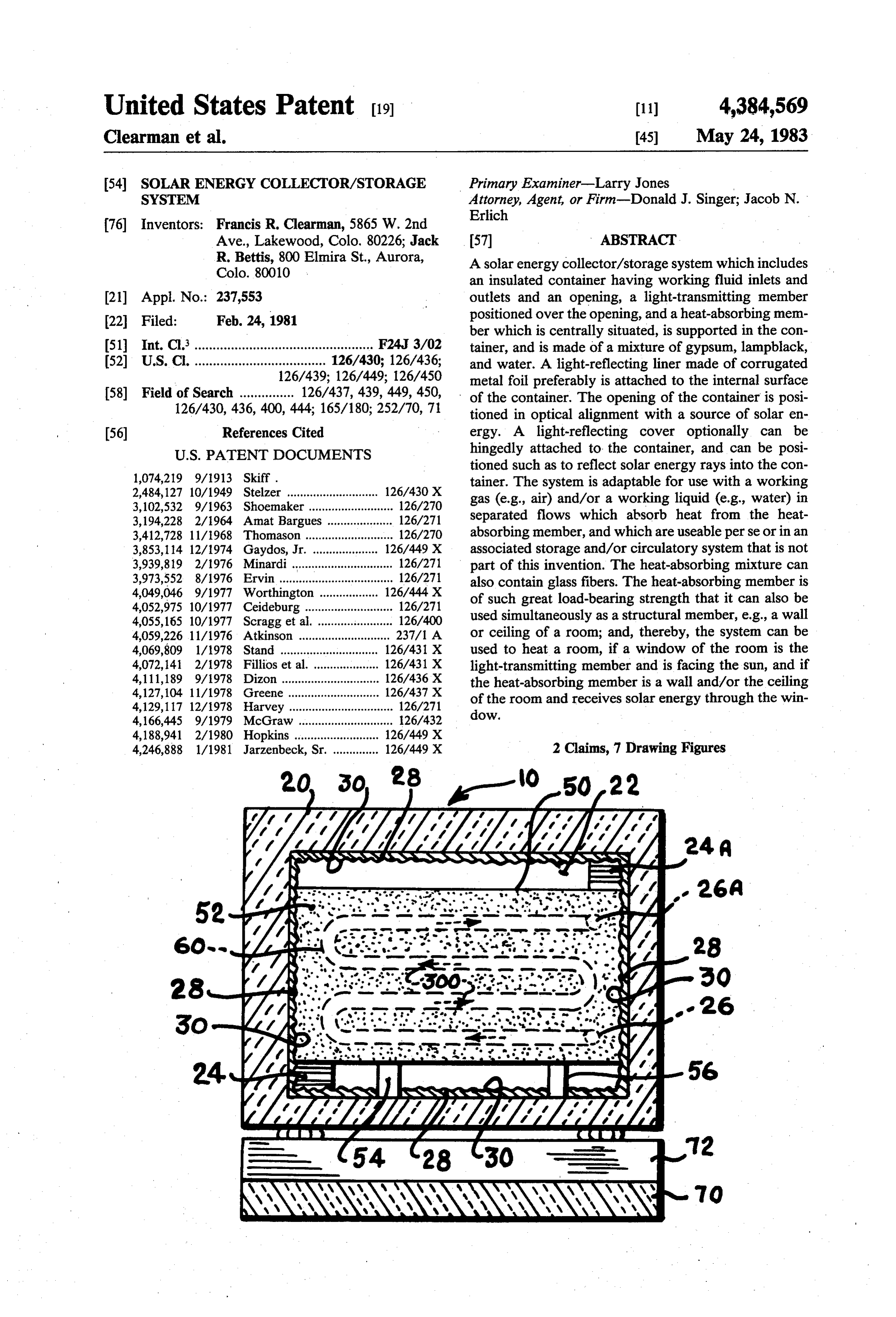
an insulated container having working fluid inlets and (21) Appl. No.: 237,553 outlets and an opening, a light-transmitting member 22 Filed: Feb. 24, 1981 positioned over the opening, and a heat-absorbing mem ber which is centrally situated, is supported in the con 51 Int. Cl.................................................. F24, 3/02 tainer, and is made of a mixture of gypsum, lampblack, (52) U.S. C. .................................... 126/430; 126/436; and water. A light-reflecting liner made of corrugated 126/439; 126/449; 126/450 metal foil preferably is attached to the internal surface 58) Field of Search ............... 126/437, 439, 449, 450, of the container. The opening of the container is posi 126/430, 436, 400, 444; 165/180; 252/70, 71 tioned in optical alignment with a source of solar en (56) References Cited ergy. A light-reflecting cover optionally can be
tioned such as to reflect solar energy rays into the con 1,074,219 9/1913 Skiff. tainer. The system is adaptable for use with a working 2,484,127 10/1949 Stelzer ............................ 126/43OX gas (e.g., air) and/or a working liquid (e.g., water) in 3,102,532 9/1963 Shoemaker .......................... 126/270 3,194,228 2/1964 Amat Bargues ..... ... 126/271 separated flows which absorb heat from the heat 3,412,728 11/1968 Thomason ........................... 126/270 absorbing member, and which are useable perse or in an 3,853,114 12/1974 Gaydos, Jr. .. ... 126/449 X associated storage and/or circulatory system that is not 3,939,819 2/1976 Minardi ............................... 126/271 part of this invention. The heat-absorbing mixture can 3,973,552 8/1976 Ervin ................................... 126/271 also contain glass fibers. The heat-absorbing member is 4,049,046 9/1977 Worthington ... ... 126/444 X of such great load-bearing strength that it can also be 4,052,975 10/1977 Ceideburg ........................... 126/271 used simultaneously as a structural member, e.g., a wall 4,055,165 10/1977 Scragg et al. ....................... 126/400 4,059,226 11/1976 Atkinson ............................ 237/1 A or ceiling of a room; and, thereby, the system can be 4,069,809 1/1978 Stand .................... ... 126/431 X used to heat a room, if a window of the room is the 4,072,141 2/1978 Fillios et al. .................... 126/431 X light-transmitting member and is facing the sun, and if 4,111,189 9/1978 Dizon .............................. 126/436X the heat-absorbing member is a wall and/or the ceiling 4,127,104 11/1978 Greene .. ... 126/437 X of the room and receives solar energy through the win 4,129,117 12/1978 Harvey ................................ 126/271 dow.
4,188,941 2/1980 Hopkins ........... ... 126/449 X 4,246,888 1/1981 Jarzenbeck, Sr. .............. 126/449 X 2 Claims, 7 Drawing Figures
SNYNYNYNYSaaSNYaYa YYA N. ASYYS
CNS:
a ray
wim
NaNa,CaCNS y Sean
(Mala Senan NASAY
sees
NNNNNNNN
Page 2
Drawing sheet — no readable text.
Page 3
Drawing sheet — no readable text.
Page 4
It is a still further object of this invention to provide
SOLAR ENERGY COLLECTOR/STORAGE a solar energy collector/storage system in which the SYSTEM working medium is a fluid, and in which the working fluid used may be a gas or a liquid, or both simulta
STATEMENT OF GOVERNMENT INTEREST 5 neously.
The invention described herein may be manufactured vide It is a yet still further object of this invention to pro and used by or for the Government for governmental concurrently a solar energy collector/storage system which purposes without the payment of any royalty thereon. build; easy to install; is: simple in structure; cheap to make or economical to use; and low in cost
BACKGROUND OF THE INVENTION 10 to maintain or repair.
This invention relates generally to solar energy col These objects of this invention, as well as other ob lector/storage systems and, more particularly, to such a jects a related thereto, will become readily apparent after consideration of the description of the invention, to system which is adaptable for use either with a working gas (e.g., air) or a working liquid (e.g., water), or with 15 gether with reference to the contents of the Figures of the drawing.
both simultaneously.
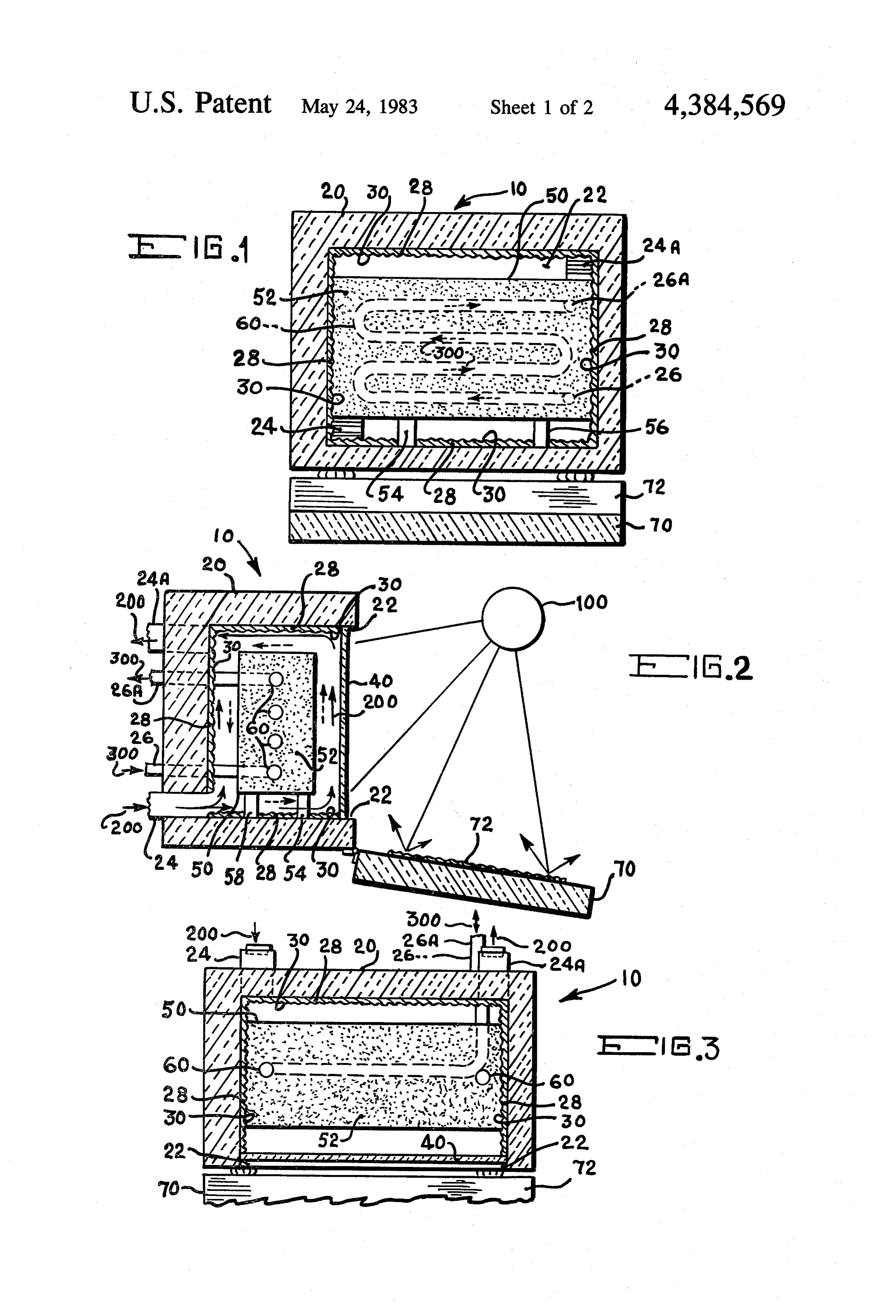
It is well known that the earth's supply of fossil fuels DESCRIPTION OF THE DRAWING is being rapidly depleted. As a result, the search for means to supplement, and hopefully to replace, fossil andFIG. 1 is a front elevation view, in simplified pictorial schematic form, of a preferred embodiment of the fuels with renewal sources of energy has begun and is 20 invention in which rapidly accelerating. It is equally well known that, (in separated flows)airmay or water, or both simultaneously be used as the working fluid;
other than nuclear-generated energy, the energy gener FIG. 2 is a side elevation view, in simplified pictorial ated by the sun is the most readily available and also the and schematic form, and partially in cross section, of the cheapest source of renewal energy. Accordingly, it is preferred embodiment in its working environment; not surprising that the technology for acquiring, retain 25 FIG. 3 is a top plan view, in simplified pictorial and ing, and selectively using the energy generated by the schematic form, and partially in cross section sun and transmitted by the sun's rays is advancing rap tially fragmented, of the preferred embodimentand par shown idly. Nevertheless, it is fair and accurate to say that to in FIGS. 1 and 2;
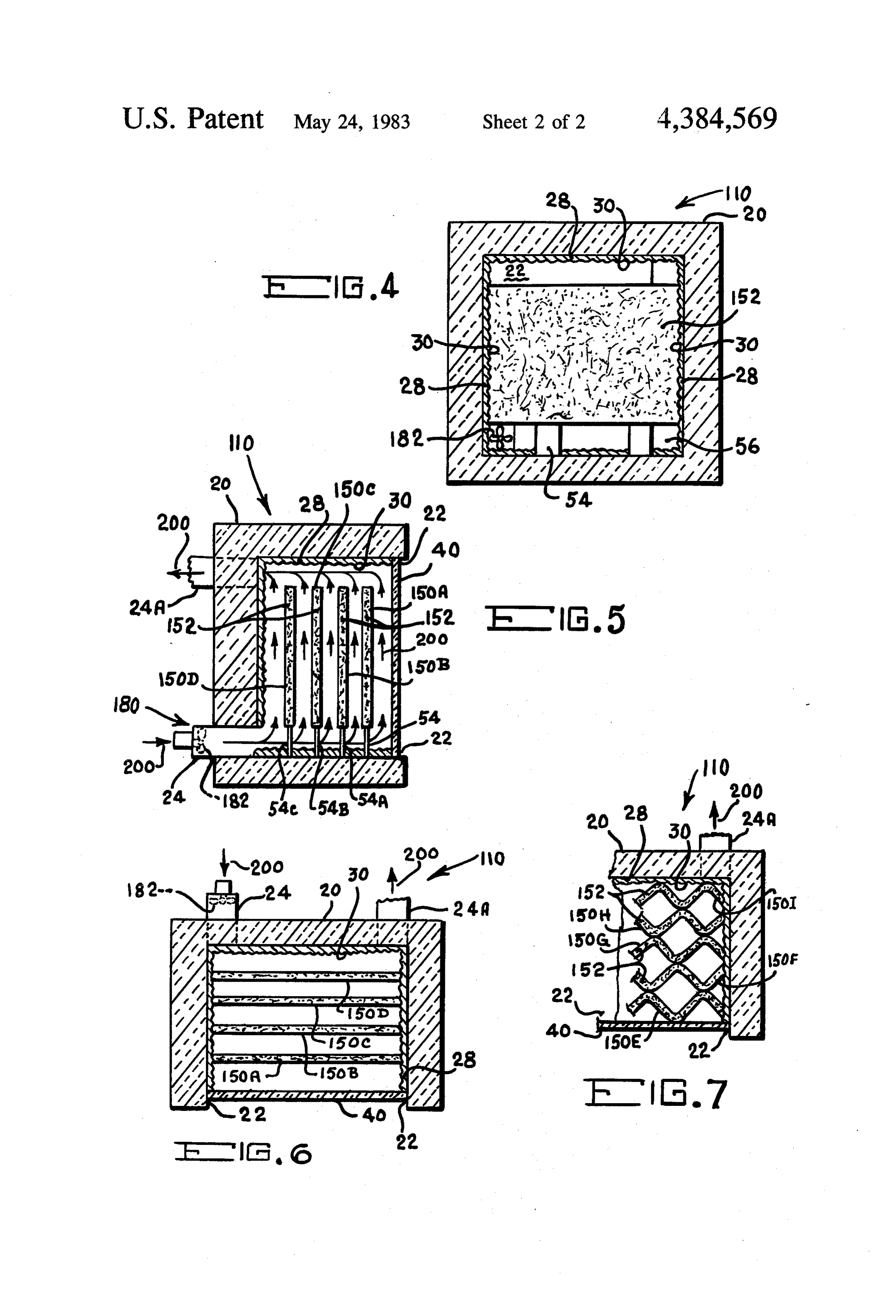
date there is not available a solar energy collector/stor age system which incorporates all of the following 30 andFIG. 4 is a front elevation view, in simplified pictorial features and advantages: simple in structure; cheap to variation of theform, schematic and partially in cross section, of a preferred embodiment, in which said make or build, because the needed materials are plenti variation only air is used as the working fluid; ful, readily available, and economical in price; easy to FIG. 5 is a side elevation view, in simplified pictorial install; economical to use; low in cost to maintain or and schematic form, and partially in cross section, of the repair; uses either a working gas or a working liquid, or 35 variation of the preferred embodiment; both simultaneously; uses, as a heat-absorbing medium, FIG. 6 is a top plan view, in simplified pictorial and materials in the form of a mixture which absorbs heat in schematic form, and partially in cross section, of the large quantities, readily heats fluids flowing on, over, variation shown in FIGS. 5 and 6, and in which a cross under or around it, and also is simultaneously useable as section structural variation of the heat-absorbing me a structural unit (e.g., a wall, a ceiling, and like); and is dium is also shown; and highly efficient both as a collector means and as a stor FIG. 7 is a top plan view, in simplified pictorial and age means of solar energy. schematic form, and partially in cross section and par SUMMARY OF THE INVENTION tially fragmented, of the variation shown in FIGS. 5 and 6, and in which another cross sectional structural
The instant invention provides all of the above-men 45 variation of the heat-absorbing medium is also shown. tioned advantages, and does so because of its novel DETAILED DESCRIPTION OF THE structure and the unique nature of the contents of the PREFERRED EMBODEMENT AND mixtures which are useable simultaneously as heat absorbing mediums and structurally-supporting mem VARIATIONS THEREOF bers. Therefore, the instant invention constitutes a sig 50 With reference to FIGS. 1-3, inclusive, therein is nificant advance in the state-of-the-art. shown in various and diverse views (as hereinbefore Accordingly, it is the principal object of the inven explained), the preferred embodiment 10 of the inven tion to provide a uniquely structured solar energy col tive solar energy collector/storage system. lector/storage system. As a preliminary matter, it is to be noted and remen it is another object of this invention to provide a new 55 bered that the term “light' is intended to mean, as it heat-absorbing medium which readily and quickly ab does in the solar energy art, "sunlight'; and, of course, sorbs great quantities of heat, and which equally, the spectrum of sunlight extends beyond visible light, readily and quickly heats fluids flowing in proximity to and includes not only visible light but also infrared and the medium. ultraviolet. It is also to be noted and remembered that It is still another object of this invention to provide a the phrase “a source of solar energy' includes, but is not heat-absorbing medium in the form of a mixture of ma limited to, sunlight directly from the (earth's) sun itself. terials previously unused in the art. In other words, the sunlight may be received from, for It is yet another of this invention to provide a heat example, a reflector from which the impinging sunlight absorbing medium which is also useable as a structural is reflected.
unit, such as a wall, a ceiling, and the like. 65 Again with reference to FIGS. 1-3, inclusive, the It is a further object of this invention to provide not preferred embodiment 10 comprises; an insulated con only a highly effective solar energy collector, but also a tainer 20 having an opening 22 in optical alignment with highly efficient storage means for the collected heat. a source of solar energy (as best shown in FIG. 2), e.g.,
Page 5
the sun 100 itself, FIG. 2; an inlet (such as either 24 or When a working liquid 300 is used, a liquid-impervi 26A, or both) for a working fluid (such as either a gas ous conduit 60 (preferably made of copper, and also 200 or a liquid 300, FIG. 2) an outlet (such as either 24A preferably having a serpentine shape) is positioned for inlet 24, or 26A for inlet 26, or both) for the working within the heat-absorbing medium 50, with the inlet of fluid, and an internal surface 28; a working fluid 200 the conduit 60 connected to the liquid impervious inlet and/or 300 (such as a gas, i.e., air 200; or a liquid, i.e., 26 of the container 20, and with the outlet of the conduit water 300) in the insulated container 20; a light-reflect 60 connected to the liquid impervious outlet 26A of the ing liner 30 disposed adjacent the internal surface 28 of container 20. The flow of the working liquid 30 into the the insulated container 20; a light-transmitting member inlet 26, through the conduit 60, and out of the outlet 40 (i.e., a translucent or transparent member) disposed 10 26A is as shown in FIGS. 1 and 2. It is here to be noted over the opening 22 of the container 20 such that the that the conduit 60 is positioned in the heat-absorbing opening 22 is closed; and, at least one member 50 which medium 50 while the constituent mixture 52 is still soft. is made of heat-absorbing material 52 disposed within Still with reference to FIGS. 1-3, inclusive, the solar the container 20. energy collector/storage system 10 preferably also has, The heat-absorbing material 52, of which the mem 15 ber(s) 50 is (are) made, comprises a mixture of gypsum but need not have, an insulated cover 70 (or door) which is dimensioned and configurated to fit on and (i.e., calcium sulfate, CaSO4.2H2O) in powdered form overspread the light-transmitting 40 and the opening 22 (e.g., in a finely divided solid state, particulate matter, pulverized, or the like), lampblack (i.e., an amorphous, in the container 20; has a light-reflecting liner 72 at tached to the "internal' surface of the cover 70 which practically pure form of carbon made by burning oil, 20 opposes the light-transmitting member 40, if the cover coal tar, resin, or other carbonaceous substance in an 70 were to be positioned such as to close the container insufficient supply of air; and, sometimes referred to as 20;
"carbon black') and a liquid, preferably water. The ableis(while attached to the container 20, and is selective mov mixture is formed in a preselected desired and/or neces fact, useablesoto attached) close and such that the cover 70 is, in to open the container 20. As sary shape, such as a block, by using a mold and allow may be readily apparent, the
cover 70 would normally ing the mixture to set until it is firm and hard.
It is to be noted and remembered that the preferred when the heated air 200 and/oris water be closed when the system 10 no longer in use, or embodiment 10, FIGS. 1-3, inclusive, is useable with a tured' (by closing all inlets and outlets)300 are "cap and held for gas working fluid 200, or with a liquid working fluid future use.
300, or with both simultaneously, although physically separated. Irrespective of what working fluid is used, It is to be noted that as a matter of preference the the heat absorbing medium 50 is preferably in the form cover 70 is also selectively positionable (by any suitable of a block which is also preferably centrally disposed conventional means) such that the light-reflecting liner within the insulated container by any conventional suit 72, which is attached to the cover 70, faces the source of able support means, such as representative supports 54, 35 solar energy 100, as is shown in FIG. 1. 56 and 58, FIGS. 1 and 2. Returning again to the structure of the container 20, If a working gas 200 is used, it is introduced into the its light-reflecting liner 30 is made of metal, preferably container 20 through inlet 24 from a suitable source (not ber corrugated metal foil; and, its light-transmitting mem shown) and it is exited from the container 20 through 40 is preferably made of a light-transparent member outlet 24A which preferably is situated in a higher posi such as glass, or "Plexiglas' (i.e., the trade name for tionable relationship with regard to the inlet 24. The transparent plastic material made from methyl methac outlet 24A is connected to a suitable conventional rylate), although this member can be made of the means (not shown), such as a circulatory system, which readily available, translucent, corrugated, plastic sheet makes use of the heated outflowing working gas 200. ing in which fibers of glass are embedded. The con The inlet 24 and outlet 24A are preferably in the struc 45 tainer is insulated with any conventional insulating ma tural form of openable and closeable adjustable louvers. terial, although "Styrofoam' (i.e., the trade name of an When a working gas 200 is used, its flow path into, expanded, cellular polystyrene) or the like is preferred. within, and out of the container 20 is structurally de The insulating material used should have an R value fined by the inlet 24, the perimeter of the heat-absorbing (i.e., an "R factor', or resistance to heat) of at least 30. medium 50, the light-reflecting liner 30, the inner sur 50 Now, returning again to the structure of the optional face of the light-transmitting member 40, and the outlet container cover 70, the liner 72 is made of metal, prefer 24A. It has been found that a secondary, and helpful ably corrugated metal foil; and, the cover 70 is insulated flow, of the working gas 200 is established within the with any insulating material having a R value of at least container 20 by the above-mentioned principal flow. 30. With regard to the liner 72, and with reference to This secondary flow is shown in FIG. 2 by dotted ar 55 FIG. 2, it is to be noted that the rays of the sunlight rows and is essentially around the supported (or sus which impinge upon corrugated metal liner 72 will pended) heat-absorbing medium 50. disperse somewhat, rather than being reflected entirely If a working liquid 300, such as water, is used, it is to and through light-transmitting member 40 of the introduced into the container 20 through inlet 26 from a container 20. Nevertheless, a sufficient amount of the suitable source (not shown) and it is exited from the 60 impinging and dispersed rays will be reflected to the container 20 through outlet 26A which is preferably light-transmittive member 40 to warrant the use of the situated at a higher level than inlet 26. The outlet 26A is corrugation-configurated metal liner 72. As a related connected to a suitable conventional means (not shown) matter, the cover 70 preferably is hingedly connected to either for storage of the heated outflowing working the lower edge of the container 20 by suitable conven liquid 300 until later use, or to a circulatory system for 65 tional means, such that the cover 70 will be down distribution and use of the heated outflowing working wardly movable only a preselected distance and is, and liquid 300. Of course, flow control valves may be con will continue to be, in optical alignment with the source nected to the inlet 26 and/or the outlet 26A. of solar energy.
Page 6
With reference to FIGS. 4–7, inclusive, therein is MANNER OF USE AND OF OPERATION OF shown a variation 110 of the preferred embodiment 10 THE PREFERRED EMBODIMENT AND THE of the inventive solar energy collector/storage system. VARATION
The variation 110 is similar to the preferred embodi ment 10 and, therefore, only the differences therebe 5 The manner of use, and of operation, of the preferred tween will be described, although the variation is embodiment 10, FIGS. 1-3, and of the variation thereof shown in full detail in FIGS. 4–7, inclusive. 110, FIGS. 4–7, can be easily ascertained by any person The principal difference in function between the vari of ordinary skill in the art from the foregoing descrip ation 110 and the preferred embodiment 10 is that the 10 tion, ures coupled with reference to the contents of the Fig of the drawing. Accordingly, it is deemed that a variation 110 is useable only with a working gas, such as description of the obvious use and operation of the 200, and not with a working liquid; whereas, as herein invention before shown and described, the preferred embodiment are at least two10 and 110 is not necessary. However, there 10 is useable with a working gas 200 or a working liquid and 110 can be applications, adapted, for which the invention 10 which may not be readily ap 300, or both simultaneously (if in separated flows).
A significant difference in structure is that in the 15 parent to those of ordinary skill in the art, and which therefore will be discussed hereinbelow.
variation 110 a plurality of members (such as 150A, Firstly, the invention 10 and 110, with air as the 150B, 150C, and 150D, best shown in FIGS. 5 and 6) working gas, can be adapted to heat a room, an office, made of heat-absorbing material are used, rather than and the like, the preferred sole one member 50 in the embodiment 10. 20 example, andincludingwith a house or an entire building. For reference to FIGS. 5 and 2, the heat
These heat-absorbing members of the plurality are dis absorbing members 150 and 150A-150D posed in spaced-apart relationship, and preferably the room dividers, partitions, or the like incana be used as particular spacing therebetween is equal. In this regard, it is to be room or office where the light-transmissive member 40 noted that these spaced-apart members of the variation is a window. In fact, because of the great structural 110 are also simultaneously disposed such that flow 25 paths (as shown in FIG. 5) for the working gas 200 strength of the mixture 52 of member 50 (and of the (which is, preferably, air) are defined by the air inlet 24, mixtures 52 orof 152 mixture 152 members 150A-150D), either of the can be used to form a structural the light-reflecting liner 30, the space between the member (such as a wall, even if load-bearing; or the spaced-apart heat-absorbing members, the light-trans ceiling) of the room or office, and thereby not only mitting member 40, and the air outlet 24A. 30 resulting in a low cost solar energy heating system for Another significant difference in structure is that the the room, but also resulting in the lowering of the cost heat-absorbing material 152 of which the members of of new houses and buildings by saving the cost of build the variation 110 are made is different than the heat ing a conventional wall and/or a ceiling in each room in absorbing material 52 of which the member 50 of the which this solar energy system is to be used. preferred embodiment is made, More specifically, the 35 Secondly, the invention 10 and 110 can be used exter heat-absorbing material 152 used in the variation 110 nally of a house or building, with air as the working gas, comprises a mixture of gypsum (i.e., in a finely divided to provide cooling air or "air conditioning' to a room in solid state, particulate matter, pulverized, or the like), a house or to an office in the building. This can be ac lampblack (i.e., an amorphous, practically pure form of complished most effectively in geographical areas carbon made by burning oil, coal tar, resin, or other 40 where the temperature differential is large, i.e., where carbonaceous substance in an insufficient supply of air; the temperature is relatively cool or cold at night, but is and, sometimes referred to as "carbon black”), glass relatively warm or hot during the day. A suitably-sized fibers, and a liquid, preferably water. Stated another member made of mixture 52 or 152 is left outdoors way, this mixture 152 includes glass fibers, while the during the night, when the "heat' that it absorbs from mixture 52 of preferred embodiment 10 does not. 45 the cool or cold air is lower in temperature (i.e., is Still another significant difference in structure is that "colder') than the warm or hot air that will be indoors the heat-absorbing members of the variation 110 are the following day during daylight hours. Then when formed in the shape of sheets, rather than the block daylight occurs, the cooled member is brought indoors, shape of the preferred embodiment. In addition, the and preferably a flow of air is promoted (i.e., caused) in structural cross sectional shape of these sheet members 50 the room by suitable means, such as a fan. The tempera may be varied. For example, representative sheets ture of the air in the room will fall, because of the en 150A-150D, inclusive, FIGS. 5 and 6, are in the struc hanced heat-absorbing capability of the "cooled' or tural cross sectional shape of thin flat sheet; whereas, "cold' heat-absorbing member.
representative sheets 150E-150I, inclusive, FIG. 7, are CONCLUSION in the structural cross-sectional shape of corrugated 55 sheets. It is abundantly clear from all of the foregoing, and A further significant difference instructure is that the from the contents of the Figures of the drawing, that the variation 110 incorporates a means (generally desig stated objects of this invention, as well as other objects nated 180) for promoting flow of the working gas 200 related thereto, have been achieved. into, through, and out of the container 20. This means It is to be noted that, although there have been de 180 preferably includes a fan 182, FIGS. 4-6, inclusive, scribed and shown the fundamental and unique features which is disposed in the inlet 24. of the invention, as applied to a preferred embodiment, Two other significant structural differences are that a variation thereof, and two novel uses thereof, various the variation 110, unlike the preferred embodiment 10, other embodiments, variations, adaptations, substitu does not have a cover or door 70, and also does not 65 tions, additions, omissions, and the like may occur to, have a liquid inlet, outlet, and other associated compo and can be made by, those of ordinary skill in the art. nents which defined and limit a flow path for a working What is claimed is:
liquid. 1. A solar energy/storage system, comprising:
Page 7
a. an insulated container having an opening in optical out said insulated container, and out of said insu alignment with a source of solar energy, an internal lated container through said working gas outlet; surface, and an inlet and an outlet for use with a c. water, as said working liquid, selectively flowing working gas, with said inlet having a fan disposed into said insulated container through said working therein to promote the flow of said working gas; liquid inlet and out of said insulated container b. air, as said working gas, flowing into said insulated through said working liquid outlet; container through said working gas inlet, through d. a light-reflecting metal liner disposed adjacent said out said insulated container, and out of said insu internal surface of said insulated container; lated container through said working gas outlet; e. a light-transmitting member made of light-transpar c. a light-reflecting metal liner disposed adjacent said 10 ent material disposed over said opening of said internal surface of said insulated container; insulated container, thereby closing said opening; d. a light-transmitting member made of light-trans f a member made of heat-absorbing material and parent material disposed over said opening of said centrally located within said insulated container, insulated container, thereby closing said opening; wherein said heat-absorbing material comprises a
e. a plurality of members made of heat-absorbing mixture of gypsum in powdered form, lampblack, material and disposed within said insulated con and water, and wherein said heat-absorbing mem tainer, wherein said heat-absorbing material com ber has a serpentine shaped conduit therein con prises a mixture of gypsum in powdered form, nected to said working liquid inlet and outlet, with lampblack, glass fibers and water, and wherein said 20 said working water flowing through said conduit, members are in the structural cross sectional shape and also wherein said positioning of said centrally of corrugated sheets having corrugations compris located heat-absorbing member is such that a flow ing alternating ridges and grooves, with said ridges path for said working air is defined by said working of said members being in contact with said grooves gas inlet, said light-reflecting liner, said light-trans of adjacent members and thereby forming voids, 25 mitting member, and said working gas outlet; and and also wherein said members are further disposed g, an insulated cover which is dimensioned and con such that flow paths for said working air are de figured to fit on and overspread said light-transmit fined by said inlet with said fan, said light-reflect ting member and said opening in said insulated ing liner, the voids between adjacent members, said container, with said insulating cover having a light light-transmitting member, and said outlet. 30 reflecting metal liner attached to a surface of said 2. A solar energy collector/storage system compris cover that opposes said light-transmitting member, 1ng: wherein said cover is attached to said insulated a. an insulated container having an opening in optical container, and is selectively movable while so at alignment with a source of solar energy, an inlet tached, such that said cover is useable to cover and and an outlet in the structural form of openable and 35 to uncover said light-transmitting member, and closeable adjustable louvers for use with a working wherein said cover is selectively positionable such gas, another inlet and another outlet for use with a that said light-reflecting metal liner attached to said working liquid, and an internal surface; cover is in optical alignment with said source of b. air, as said working gas, flowing into said insulated solar energy.
container through said working gas inlet, through
Provenance
- Collection
- Cited prior art
- Original PDF
- patentimages.storage.googleapis.com →
- Filed
- 1981-02-24
- Pages
- 7
- Method
- pdftotext (the PDF's own text layer) + pdftoppm 300dpi page scans
- Source
- Google Patents bibliographic record
- Granted
- 1983-05-24
- Inventors
- Francis R. Clearman; Jack R. Bettis
- Transcribed from
- patentimages.storage.googleapis.com →