patent · US4246888
Solar heat collecting apparatus
27 January 1981
Page 1 — bibliographic record
United States Patent (19) 11) 4,246,888 Jarzenbeck, Sr. 45 Jan. 27, 1981
(54) SOLAR HEAT COLLECTING APPARATUS 4,129,117
76 Inventor: Jerome F. Jarzenbeck, Sr., #24 W.
R.R. #1, South Sioux City, Nebr. Primary Examiner-James C. Yeung 68776 Assistant Examiner-Daniel O'Connor
Attorney, Agent, or Firm-Henderson & Sturn
22 Filed: May 14, 1979 (57) ABSTRACT 51 Int. Cl. ................................................. F24J 3/02 A combined solar heating apparatus for heating air or 52 U.S.C. .................................... 126/429; 126/430; water or both air and water comprising a corrugated 126/448; 126/449 collector plate with S-shaped tubing traversing the 58) Field of Search ............... 126/429, 446, 447, 448, enclosure beneath the plate. The rear of the corrugated 126/436, 430,417, 449, 445 plate is enclosed so as to allow filling of the air space with an aggregate material to provide increasing tem (56) References Cited perature and heat storage characteristics. A continuous
3,815,574 6/1974 Gaydos ................................ 126/436 S-shaped loops passing through the rear of the collector 3,902,474 9/1975 Pyle ...................................... 126/449 plate and through the aggregate. A rear wall member is 3,952,725 4/1976 Edmondson ... 126/447 attached to the back of the corrugated collector to form 4,059,226 11/1977 Atkinson ... ... 126/427 an air enclosure. A transparent plate sealingly encloses 4,068,652 1/1978 Worthington ........ ... 126/429 the top of the collector, providing an air space between 4,083,360 4/1978 Courvoisier et al. . ... 126/447 the collector plate and the transparent cover. 4,088,266 5/1978 Keyes.................... ... 126/449 4,099,513 7/1978 Skrivseth ... 126/449 4,119,083 10/1978 Heyen .................................. 126/449 1 Claim, 8 Drawing Figures
Still
AaaaaaaaaaaZZZZY
YaNNX&Y&N as a Nayer NSS S
See s axSar aZZZZZZZZZ ZZZZazas
22 E.
Page 2
Drawing sheet — no readable text.
Page 3
Drawing sheet — no readable text.
Page 4
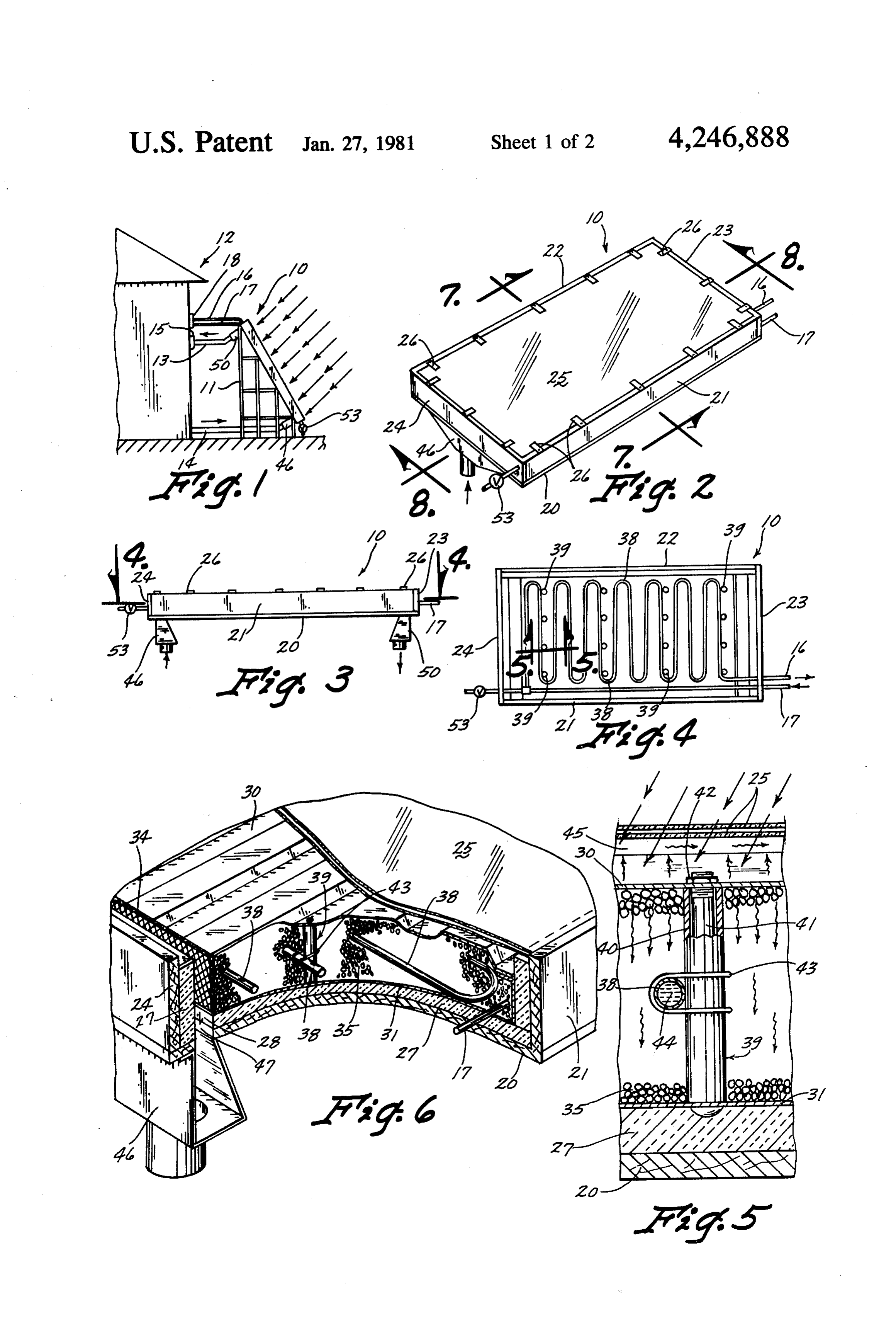
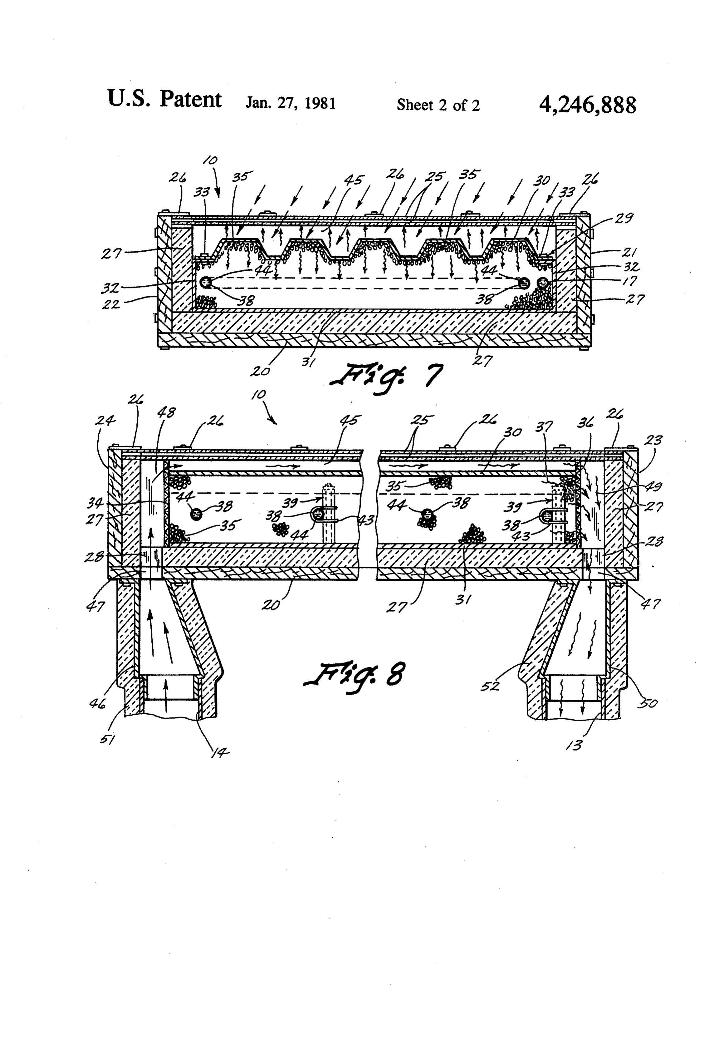
FIG. 6 is an enlarged partial cross-sectional perspec
SOLAR HEAT COLLECTING APPARATUS tive and broken-away view of the solar collector show ing various parts thereof;
BACKGROUND OF THE INVENTION FIG. 7 is a cross-sectional view taken along line 7-7 The use of solar energy to provide heating is well of FIG. 2; and known in the art. The conventional collector is com FIG. 8 is a cross-sectional view taken along 8-8 of
prised of a collector plate to absorb radiant energy and transfer this energy in the form of heat through the DESCRIPTION OF THE PREFERRED collector plate to a heat storage unit for subsequent 10 EMBODIMENT usage. Solar heaters have been used in a variety of appli Referring now to the drawings where in like refer cations to produce heated air, water and electricity. ence numerals designate identical or corresponding One of the major problems associated with these heat parts throughout the several views, FIG. 1 shows a collectors is the efficiency of the collector. Another solar collector 10 mounted on a stand 11. The solar problem is the relative cost of these collectors to the 15 collector 10 is attached to a building 12 by means of an consumer. Consequently, there is a need for a solar heat inlet air conduit 13 and an outlet air conduit 14. A fan collecting apparatus for solving these problems. 15, shown schematically in FIG. 1 causes circulation of
SUMMARY OF THE INVENTION
air through the inlet 13, solar collector 10 and air inlet 14. Additionally, a water inlet pipe 16 and a water outlet
The present invention relates to a solar heat collect 20 pipe 17 are connected from the solar collector 10 to the ing apparatus having an insulated frame including a building 12. A pump 18 is connected in either line 16 or back, sides, a top and a bottom. The back has slots and 17 for providing circulation through the solar collector therein for providing an air inlet and outlet. Collecting water lines 16 and 17.
Referring now with more particularity to the solar structure, including a front plate and a back plate are 25 collector disposed within the frame. An aggregate material such tor 10 includes 10 shown in FIG. 2, it is noted that the collec as gravel is disposed between the front and back collec 22, a top 23 and aa frame having a back 20, sides 21 and tor plates. A conduit constructed of a highly heat con (double-pane) front cover24.bottom In addition, a thermopane 25 is sealingly secured to the ductive material is located between the front and back front of the collector 10 by means of a plurality of plates of the collecting structure for providing a path 30 clamps for fluid flow therethrough. A cover is sealingly at of securing 26. It is to be understood that many other ways tached to a front portion of the frame for allowing rays out departingthefrom cover 25 to the frame can be used with the spirit and scope of this invention.
of sunlight to pass therethrough. Additionally, an air Referring to FIG. 7, for example, it is noted that a passageway is provided between the front plate and the two-inch layer of insulation 27 is disposed entirely cover in communication with the air inlet and air outlet. 35 around the inside of the frame, with the exception of an An object of the present invention is to provide a opening 28 therein which will be referred to below. A combination air and water solar heater which is signifi solar collecting structure 29 is disposed within the cantly more efficient than previously disclosed collec frame and within the insulation 27, and additionally tors. below the thermopane covering 25, as can clearly be Another object of the invention is to improve the 40 seen in FIG. 7. This collecting structure 29 includes a heat storage capacity of a storage solar collector while front plate 30 which is corrugated in structure and a flat reducing its size. a back plate 31 which plates are connected together by A further object of the invention is to provide an sides 32 and a plurality of fasteners 33 connected inexpensive portable solar collection unit. through the edges of the corrugated front plate 30 and Still another object is to provide a solar collection 45 a flange 34 connected to the sides 32. The front plate 30 apparatus which will heat air or water or both air and is preferably constructed of steel which has a galva Water. nized coating on all sides thereof. An epoxy primer is A still further object of the invention is to provide a then coated over the galvanized layer. A dark bronze heat storage method wholly within the collector to 50 coat of fluorcarbon based enamel containing polyvinyli increase temperature and heat retention. dene fluoride which can be purchased under the trade mark KYNOR is then placed on the top side of the
Other objects, advantages and novel features of the corrugated present invention will become apparent from the fol slating is placed front plate 30. Then a coat of chalkboard lowing detailed description of the invention when con coat of 3M brandonneotel-black the top side over the enamel; and, a sidered in conjunction with the accompanying draw 55 on top of the chalkboard slating.velvet It 101-C10 is painted has been determined
IngS.
that this combination is very excellent for the purpose
BRIEF DESCRIPTION OF THE DRAWINGS of absorbing sunlight but yet retarding the emmission of heat back out thereof.
FIG. 1 shows a side-elevational view of the present A wire screen mesh 34 is attached across the bottom invention shown to attached to building; 60 ends of the collector structure 29 as can best be seen in FIG. 2 is a perspective view of the solar collector of FIG. 8. Gravel 35 is then placed within the collector the present invention; structure 29, although the gravel can be placed in at any FIG. 3 is a side-elevational view of the solar collector other time which is convenient. Once the gravel is in shown in FIG. 2; place then a top metal screen structure 36 is placed over FIG. 4 is a cross-sectional view taken along line 4-4 65 the top end of the collector structure 29 as can best be of FIG. 3; seen in FIG.8. These screens 34 and 36 hold the gravel FIG. 5 is an enlarged partial cross-sectional view between the front and rear plates 30 and 31 respectively taken along line 5-5 of FIG. 4; but allow heat to rise and pass through the gravel and
Page 5
out through the top screen 36 as shown by the arrows above, by merely allowing the heated air to rise or 37 in FIG. 8. preferably by using a circulating fan 15 for forcing the Referring now to FIGS. 4, 5 and 6 it is noted that air through the solar collector 10. copper tubing 38 formed in partial loops or S-shaped It is important to note that the present invention can loops is provided within the gravel 35. Spacer struc 5 be used to heat the air only by not circulating the water tures 39 are provided for holding the front plate 30 and 44 through the pipe 38, for example by not running the the back plate 31 in a particular spaced relationship pump 18. Also, the present invention can be used to heat while further providing a means for supporting and primarily, if not only, the water 44 by not using the holding the copper tubing 38 in a predetermined rela forced air fan 15 and utilizing only the pump 18. tionship with respect to the gravel and with respect to 10 Thirdly, the present invention can be used for heating the front and back plates 30 and 31 respectively. The both the water 44 and the air as described in detail in the spacer members 39 include a tube 40, a bolt 41 passing paragraph above and by utilizing both the forced air fan therethrough and a threaded nut member 42 threadedly 15 and the pump 18.
secured to one end of the bolt 41 as can best be seen in Obviously many modifications and variations of the FIG. 5. The copper tubing 38 is secured to the spacer 15 present invention are possible in light of the above members 39 by means of a wire 43, but it is to be under teachings. It is, therefore, to be understood that, within stood that other securing mechanisms can be used. It is the scope of the appended claims, the invention may be important to note, however, that if more heat is desired practiced otherwise then as specifically described. to be applied to the water 44 within the copper tube 38, I claim:
then the copper pipe 38 would be placed closer to the 20 1. A solar heat collecting apparatus comprising: front plate 30, while, conversely, if it is desired to pro an insulating frame means including a back, sides, a vide more heat to the air within the passageway 45 than top and a bottom, said back having slot means to the fluid 44 within the tubing 38, then the tube 38 therein for providing an air inlet and outlet; would be placed closer to the back plate 31 then to the collecting means including a front plate and a back front plate 30. This placement can be used to adjust the 25 plate disposed within said frame means; relative amount of heat to be applied to the water 44 or an aggregate material disposed between the front and to the air in the space 45, as will be clearly understood back collector plates;
to those skilled in this art. conduit means constructed of a highly heat conduc Referring now more particularly to the way that the tive material, said conduit means being disposed air is heated utilizing the solar collector 10 it is noted 30 between the front and back plates of said collecting with attention directed to FIGS. 3, 6 and 8 that an inlet means for providing a path for fluid flow there connector 46 is connected to the bottom of the solar through;
collector 10 and connects the line 14 from the building cover means sealingly attached to a front portion of 12. The air passes into the connector 46 and through an said frame means for allowing rays of sunlight to elongated opening 47 disposed in the back of the frame 35 pass therethrough;
20. The air then passes through an opening 28 in the air passageway means being formed between said insulation and between the screen 34 and the insulation front plate and said cover means, said air passage 27 adjacent the bottom 24 of the frame. way means being in communication with said air Referring now to FIG. 8, it is noted that arrow 48 inlet and air outlet;
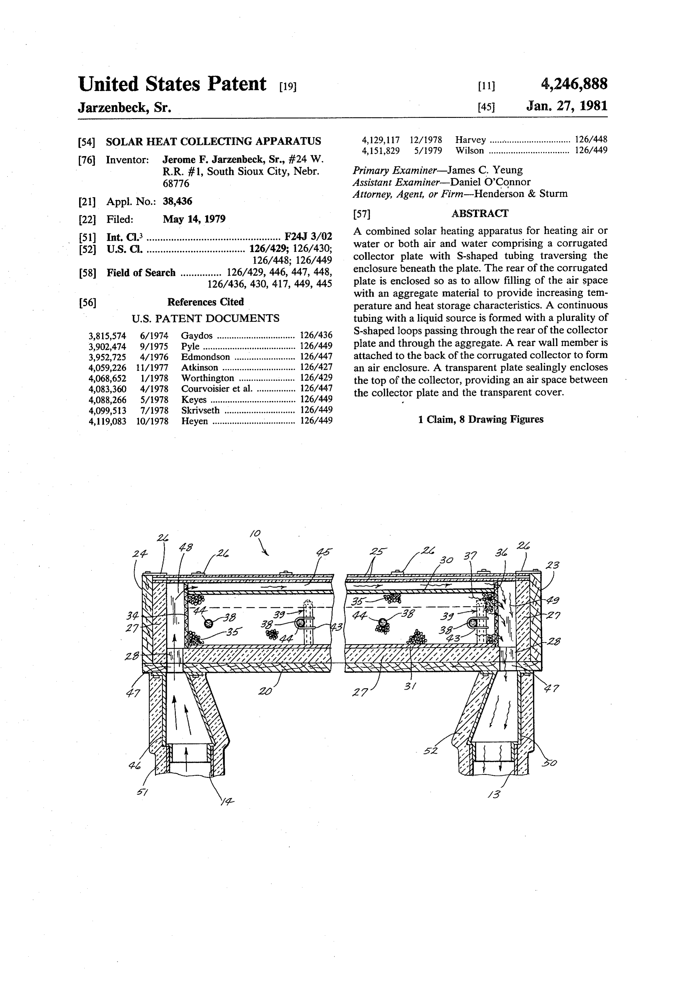
shows how the air passes from the underside of the 40 wherein a screen is disposed across each of the ends screen to the space 45 between the front plate 30 and the of said front and back collector plates and attached thermopane cover 25. This air, as it passes through the thereto wherein said aggregate material is held opening 45, is heated by the heat which is absorbed into between said front and back collector plates and the front plate 30 and which tends to be stored within heated air is allowed to move through said screen; the gravel 35; and, this air eventually passes through a 45 wherein said aggregate material completely fills said top opening 49, through the passageway 28 on the right collecting means;
side of FIG. 8, a top passageway 47 through the back 20 wherein said aggregate material is gravel; of the frame and then out through a top connector wherein said front and back collector plates are con member 50 to the pipe 13 which leads the heated air structed of galvanized steel; back to the building 12. it is noted that insulation 51 and 50 wherein said front plate is corrugated and said back 52 is provided around the connectors 46 and 50 as well plate is flat;
as around the pipes 3 and 14 to prevent the transfer of wherein said front plate includes an epoxy primer on heat to the atmosphere. Likewise, insulation would top of the galvanized steel, a coat of dark bronze actually be provided around the pipe 16 and 17 which colored fluorocarbon based enamel containing are shown in FIG. 1 and which lead to the building 12 55 polyvinylidene fluoride on top of the epoxy primer, to be heated. a coat of chalkboard slating on top of the fluorocar In operation, the solar collector would be shown as bon based enamel and a coat of 3M brand nextel indicated in FIG. 1. When not in use, a drainage valve black velvet 101 - C10 on top of the chalkboard 53 can be utilized to drain all of the water out of the pipe slating;
38 so that it will not freeze. When the sun is shining, the 60 wherein said conduit means is formed into a series of rays of sunlight will pass through the glass thermopane partial loops;
cover 25 and strike the front plate 30. This solar heat wherein one end of said frame means is disposed at a will be transferred to the gravel 35, to the copper pipe higher elevation than the other end thereof 38 and ultimately to the water 44 therein. When the whereby air heated in said air passageway means pump 18 is functioning, this water will be transferred to 65 rises into said air outlet including valve means the inside of the building 12 to be used for any uses for attached to a bottom portion of said conduit means which hot water is needed. At the same time, heated air for draining fluid from said conduit means, includ can be circulated through the collector 10, as described ing pump means attached to said conduit means for
Page 6
circulating fluid through said conduit means, in plate for holding said front and back plates a prede cluding means for connecting said air inlet to an termined distance apart;
wherein each of said spacer means comprises a tube, enclosure to be heated and means for connecting bolt means extending through said tube and said air outlet to said enclosure, including fan through the front plate and back plate and having means disposed in one of said inlet or outlet con nut means threadably disposed on one end of said necting means for circulating air through said air bolt means, including means for attaching said conduit means to said spacer means for fixing the passageway means and said enclosure, including a position of said conduit means with respect to said plurality of spacer means disposed within said ag 10 front and back plates
ofk said
collecting means.
gregate and between said front plate and said back
Provenance
- Collection
- Cited prior art
- Original PDF
- patentimages.storage.googleapis.com →
- Filed
- 1979-05-14
- Pages
- 6
- Method
- pdftotext (the PDF's own text layer) + pdftoppm 300dpi page scans
- Source
- Google Patents bibliographic record
- Granted
- 1981-01-27
- Inventors
- Jerome F. Jarzenbeck, Sr.
- Transcribed from
- patentimages.storage.googleapis.com →