patent · US2969788
Solar energy collectors
31 January 1961
Page 1
Drawing sheet — no readable text.
Page 2
United States Patent Office 2,969,788 Patented Jan. 31, 1961
and is equipped with a transparent glass cover 30 com posed of a pair of spaced apart glass plates 31 and 32 2,969,788 in order to restrict or retard the dissipation of heat from SOLAR ENERGY COLLECTORS the chamber. The cover is preferably coated to reduce reflection or is formed from a non-reflective type of glass.
Alwin B. Newton, Wichita, Kans, assignor to The Cole As shown most clearly in Figures 2 and 3, the sides man Company, Inc., Wichita, Kans, a corporation of
Kansas and bottom of casing 26 are double-walled. Between the inner walls 33a and the outer walls 33b is a layer of
Filed July 1, 1957, Ser. No. 669,150 insulating material 33c. The insulating layer may be 0. composed of any suitable material capable of preventing 4 Claims. (C. 126-271) or retarding the dissipation of heat through casing 26. If desired, reflecting wings 34 may be mounted on all four sides of casing 26. These wings are angled upwardly and outwardly, and have reflective upper surfaces adapted
This invention relates to high temperature Solar energy 15 to collectors. reflect direct rays of sun-light upon reflectors 29. A major defect of present solar energy collectors lies suitablestructure
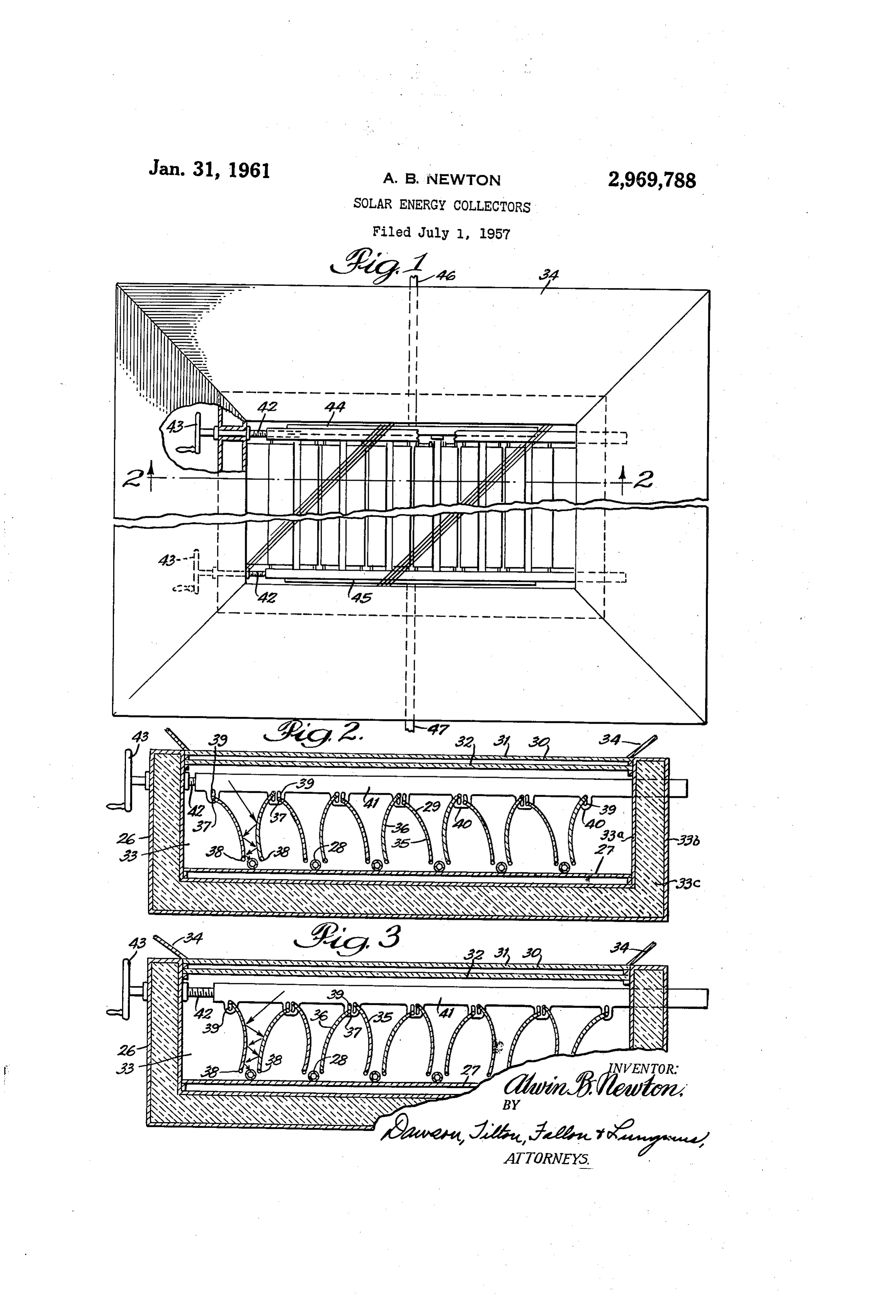
The for a illustrated in the drawings is particularly rigid or permanent installation. A rigid in their failure to develop high enough temperatures to mounting of the collector is desirable because it obviates permit efficient utilization of the energy converted by the the need for flexible or adjustable piping to and from the collectors. For example, where heat from a Solar energy 20 unit. However, to obtain maximum collector efficiency collector is intended to be used in developing power, the at any given time of the day, adjustment means are pro efficiency of the thermodynamic cycle will depend largely vided for varying the positions of the reflector elements. upon the degree of temperature attained. Consequently, From Figures 2 and 3, it will be seen that each of the the failure of conventional collectors in heating circulat reflectors 29 is longitudinally divided to provide a pair of ing fluids to sufficiently high temperatures results in in 25 separate side plates 35 and 36. Each of the side plates efficient operation of the accompanying power units.
Similarly, where heat is to be transferred and stored forms one leg of a V-shaped reflector, and has a highly reflective, convex outer surface and a reflective concave for later use, it is apparent that the amount of fluid or inner surface. The first and last plates of the reflector other material necessary to store a given amount of heat series are identical in shape and size to the side plates is dependent upon the temperature to which the material 30 is heated. Stated differently, a quantity of heat-retaining 35Atandthe36ends of the composite reflectors 29. material raised to a relatively high temperature may hold upper and lowerofedges each reflector plate, and adjacent the thereof, are a pair of outwardly as much heat as a larger amount of similar material at a projecting pins or shafts 37 and 38, respectively. Lower lower temperature. Therefore, in solar energy heating pins 38 are rotatably received systems, regardless of whether the heat is to be stored or spaced along the lower portion by 35 openings (not shown) of the inner side walls of transferred to power means, it is advantageous to provide the a solar energy collector which is capable of attaining high pivotcasing. Consequently, the reflector plates are free to about pivotal axes extending along their lower edges.
temperatures.
Upper pins 37 are freely carried within the vertically
Therefore, one of the main objects of the present inven 40 elongated tion is to overcome the aforementioned defects of present adjustmentslots 39 provided by the depending tabs 40 of bars 41.
solar energy collectors. Another object is to provide a The adjustment bars are longitudinally slidable within solar energy collector equipped with means for intensify chamber 33 along opposite side walls of casing 26. One ing and concentrating the Sun's rays upon a series of fluid end of each bar projects through an opening in one wall carrying conduits, so that the fluid within the conduits is heated to a substantially higher temperature than in con 45 of the casing, and is slidably received therein. The op posite end of each bar is equipped with a threaded bore ventional collectors.
The heat of this fluid may then be stored by the fluid adapted to receive threaded shaft 42. As shown most clearly in Figure 1, the two threaded shafts are journaled itself, or it may be transferred to some other medium in the casing wall, and are freely rotatable with reference and stored as latent heat. Another object is to provide a 50 thereto. The outer ends of the shafts may be provided solar energy collector having reflectors adapted to con with control wheels or handles 43 for rotating the shafts centrate the direct or diffused rays of the sun, and adapted and driving the adjustment bars 41 longitudinally within to prevent the escape of heat from other parts of the the casing chamber.
collector. A still further object is to provide a high tem perature solar energy collector having adjustable reflector 55 of The collector of Figures 1-3 is provided with a series parallel heat collecting tubes 28 arranged between and means adjacent the elements to be heated, the reflectors below adjacent reflectors 29. Each of the tubes has its being adjustable to provide maximum concentration of opposite end in communication with an inflow manifold the sun's rays upon the heating elements throughout the 44 and an outflow manifold 45. The manifolds in turn day.
communicate with inflow conduit 46 and outflow conduit
Other objects will appear from the specification and 60 47, respectively. It will be seen, therefore, that this ar drawings, in which rangement provides for parallel fluid flow through the heat Figure 1 is a broken top plan view of a solar energy collecting tubes 28. However, it is to be understood that collector embodying the present invention; Figure 2 is a the Series flow arrangement may be substituted for the broken vertical cross section taken along lines 2-2 of present fluid flow structure, Figure 1 and illustrating the adjustable reflectors tilted 65 For most efficient operation of the solar energy col in one direction; Figure 3 is a cross sectional view similar lector, it is desirable to support casing 26 so that the cover to Figure 2 but showing the reflectors angled or tilted 30 is generally perpendicular to the plane defined by the in a second or opposite direction.
Referring to the drawings, Figures 1-3 show a solar Sun's path of travel, during the time of the year when heat collection is desired, i.e., in most cases, during the energy collector comprising an enclosure or casing 26, a winter flat coil-supporting plate 27, fluid carrying tubes 28 and 70 to months. Control wheels 43 may then be rotated curved reflectors 29. The casing defines a chamber 33 35 shift adjustment arms 41 and pivot the reflector plates and 36 into whatever position produces the greatest

Page 3
concentration of solar radiation on heat collecting tubes tween adjacent reflectors. It is apparent that the precise 28. For example, in the morning hours, it may be desir curvature necessary to obtain this result will depend in a able to pivot the reflector plates into the position shown large part upon the particular spacing of the heat tubes in Figure 2, so that the sun's rays will strike the reflector and the depth of the whole unit. plates as indicated by the arrows, and will be intensified While in the foregoing I have disclosed an embodi and concentrated upon the fluid carrying tubes. Later in ment of the invention in considerable detail for purposes the day, the reflector plates may be pivoted into the of illustration, it will be understood by those skilled in positions shown in Figure 3 to maintain the high concen the art that many of these details may be varied without tration of the rays despite the changed position of the departing from the spirit and scope of the invention. sun. It will be understood that shaft 42 may be syn O I claim: . . - chronized for operation by a single control wheel and , 1. in a high temperature solar energy collector, a cas that, if desired, these shafts may be turned by power ing providing a chamber therein and equipped with a means (not shown) to change automatically the positions transparent cover for admitting sun-light into said cham of the reflectors with reference to the changing position ber, a series of elongated parallel reflectors mounted of the sun throughout the day. within said chamber, said reflectors each comprising a pair The inner concave surfaces of the reflector plates are of downwardly and outwardly diverging side plates in highly reflective to prevent the escape of heat from tubes dependently mounted upon said casing for pivotal move 28, and plate 27 is formed of a material having low enis ment about the lower edges thereof and being reflective sivity so as to reflect heat rays back towards tubes 28 on opposite surfaces thereof, a plurality of elongated heat and the undersurfaces of reflectors 35 and 36. Water or 20 collecting tubes each mounted within said casing between other fluid which flows through the heated tubes passes the lower edges of the side plates of adjacent reflectors, from the collector through outlet conduit 47, and may be and means for simultaneously pivoting said plates into se used for power or heating means or may be stored in a lected positions for concentrating solar rays upon said suitable reservoir for later use. Also, the collector may heat collecting tubes.
transfer heat to some other material for latent heat stor 2. The structure of claim 1 in which a flat plate is age. In this connection it will be noted that the present mounted within said chamber below said heat collecting invention permits a greater range of selection of melting tubes and below said reflectors, whereby the reflective materials for latent heat storage because of the rela inner surfaces of said reflector plates reflect heat rays tively high temperatures obtained by the collector. from said flat plate back towards the same. Reflectors 29 may be formed from polished aluminum 30 mounted3. The structure of claim 1 in which said pivotally reflector plates are provided with convex outer sheet material, from stainless steel, or from any other surfaces and highly reflective and durable material. As shown in Fig concave inner surfaces. 4. A high temperature solar energy collector compris ures 2 and 3, the downwardly diverging side walls of ad jacent reflectors define tapered passages leading towards ing a casing having a transparent cover and defining a parallel sections of the heat collecting tubes. Sunlight 35 chamber therein, a plurality of elongated parallel re passing downwardly through cover 30 strikes the highly flectors mounted within said chamber, said reflectors each reflective convex surfaces of reflectors 29 and is directed having a generally inverted V-shaped cross section and downwardly towards the tubes. As represented by the each having side walls providing reflective convex outer arrows in Figures 2 and 3, the curvature of the reflectors surfaces, and a plurality of elongated heat collecting tubes is developed so that rays striking their outer surfaces are 40 each being disposed parallel to and between the lower reflected back and forth between adjacent reflectors and edges of adjacent reflectors, said reflectors extending up are thereby intensified and concentrated upon tubes 28. wardly above and between said tubes, each of said elon Consequently, the tubes, which are formed from copper gated reflectors being, longitudinally divided and being or other heat conductive material, are heated to a con provided with a pair of side walls, each of said side walls siderably higher temperature than the collecting tubes of 45 being independently and pivotally carried at its ends by conventional non-concentrating solar energy collectors. said casing, and means for simultaneously pivoting the As tubes 28 are heated by the solar rays reflected and side walls of all of said reflectors according to the posi intensified by reflectors. 29, some of the heat will be tion of the sun, whereby, sun-light striking said reflectors conducted to plate 27 upon which the tubes are mounted. 50 is reflected back and forth between the convex surfaces Although plate 27 is a relatively poor heat conductor, its of adjacent reflectors and is concentrated upon the heat low emissivity in the larger wave length ranges results in collecting tubes disposed therebetween. the reflection of heat back to the undersides of reflectors 29, and these heat rays will then be reflected back and References Cited in the file of this patent forth until they strike heat-collecting tubes 28. Below 55 UNITED STATES PATENTS the plate 27 is a dead air space which serves to insulate the plate and prevent heat loss in that direction. Hence, 748,696 Browning ---------------- Jan.5, 1904 the escape of heat from tubes 28 and from plate 27 is 966,070 Bailey ------------------ Aug. 2, 1910 effectively prevented by the opposing reflective surfaces 980,505 Emmet ------------ ------Jan. 3, 1911 of the plate and the reflectors which re-direct heat rays 60 1,074,219 Skiff ------------------- Sept. 30, 1913 emanating from the tubes 28 back to those tubes. '1201,536 Whitehead ---------- -- Oct. 17, 1916 A reflector of "developed” shape is herein defined as a 1946, 184 Abbot ------------------ Feb. 6, 1934 reflector having a cross section in the general shape of an 2,249,642 Turner ---------------- July 15, 1941 inverted V, with its side walls bowed outwardly to pro 2293,735 Hardgrove ------------- Aug. 25, 1942 vide convex outer surfaces and concave inner surfaces, so 65 2,316,191
that rays striking the outer surfaces of the reflectors will be directed towards the heat carrying tubes disposed be
Provenance
- Collection
- Cited prior art
- Original PDF
- patentimages.storage.googleapis.com →
- Filed
- 1957-07-01
- Pages
- 3
- Method
- pdftotext (the PDF's own text layer) + pdftoppm 300dpi page scans
- Source
- Google Patents bibliographic record
- Granted
- 1961-01-31
- Inventors
- Alwin B Newton; Coleman Co Inc
- Transcribed from
- patentimages.storage.googleapis.com →