patent · US3853114
Solar heat absorber
10 December 1974
Page 1 — bibliographic record
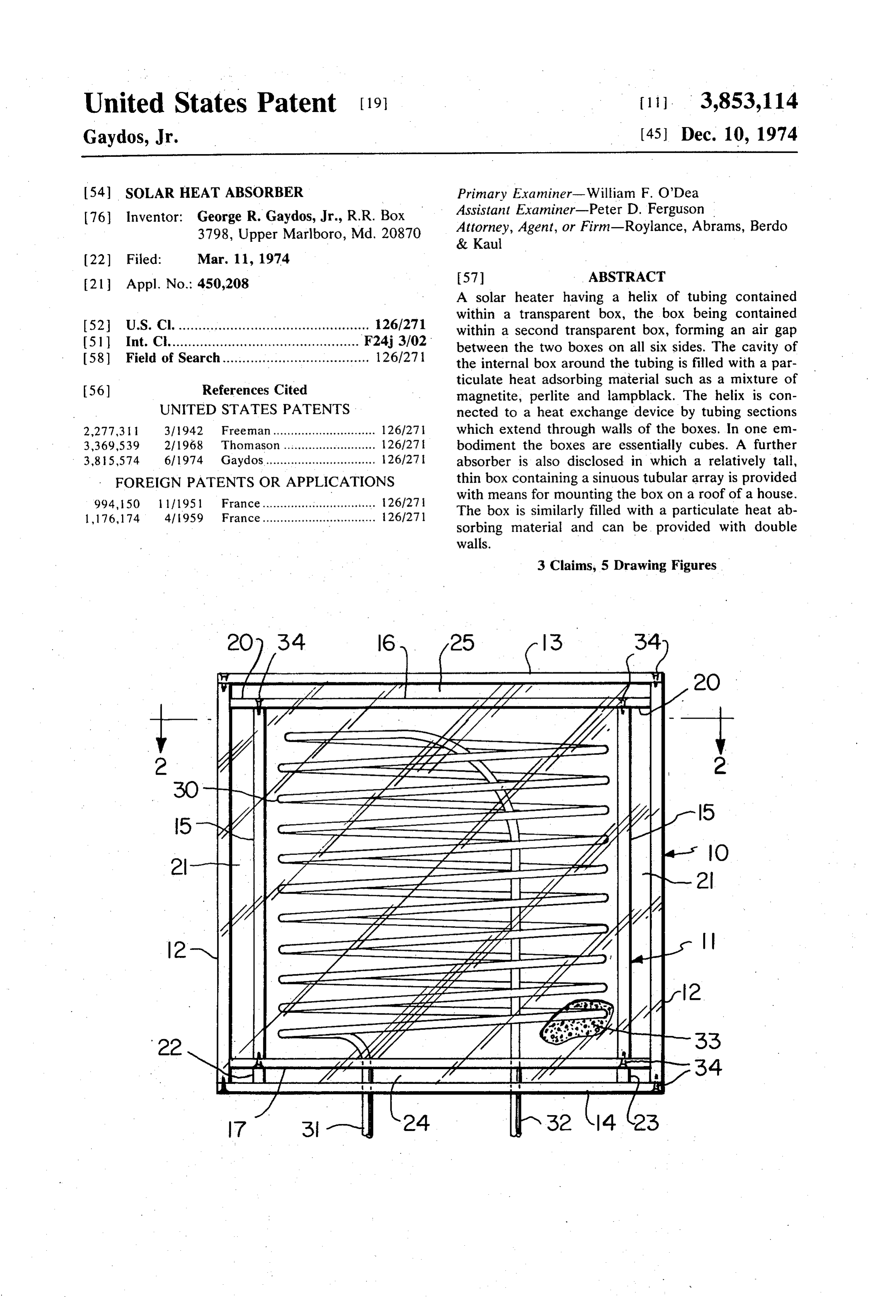
United States Patent (19) 11 3,853,114 Gaydos, Jr. (45) Dec. 10, 1974 54). SOLAR HEAT ABSORBER Primary Examiner-William F. O'Dea 76) Inventor: George R. Gaydos, Jr., R. R. Box Assistant Examiner-Peter D. Ferguson 3798, Upper Marlboro, Md. 20870 Attorney, Agent, or Firm-Roylance, Abrams, Berdo & Kaul
21 Appl. No.: 450,208 57 ABSTRACT A solar heater having a helix of tubing contained within a transparent box, the box being contained 52 U.S. Cl. ................................................ 126/271 within a second transparent box, forming an air gap (5ll Int. Cl................................................ F24.j 3/02 between the two boxes on all six sides. The cavity of 58) Field of Search..................................... 126/271 the internal box around the tubing is filled with a par
ticulate heat adsorbing material such as a mixture of magnetite, perlite and lampblack. The helix is con
UNITED STATES PATENTS nected to a heat exchange device by tubing sections 2,277.3 3/1942 Freeman............................. 126/27 which extend through walls of the boxes. In one em 3,369,539 2/1968 Thomason .......................... 126/27 bodiment the boxes are essentially cubes. A further 385,574 6/1974 Gaydos................................ 126/27 | absorber is also disclosed in which a relatively tall, FOREIGN PATENTS OR APPLICATIONS thin box containing a sinuous tubular array is provided 994, 150 l l 11951 France................................ 26/27 i with means for mounting the box on a roof of a house. 1,176,174 4/1959 France................................ 126/271 The box is similarly filled with a particulate heat ab sorbing material and can be provided with double walls.
3 Claims, 5 Drawing Figures
Page 2
Drawing sheet — no readable text.
Page 3
Drawing sheet — no readable text.
Page 4
SOLAR HEAT ABSORBER Walls 15 are preferably made of Plexiglass or a simi lar plastic material which has a relatively low coeffi
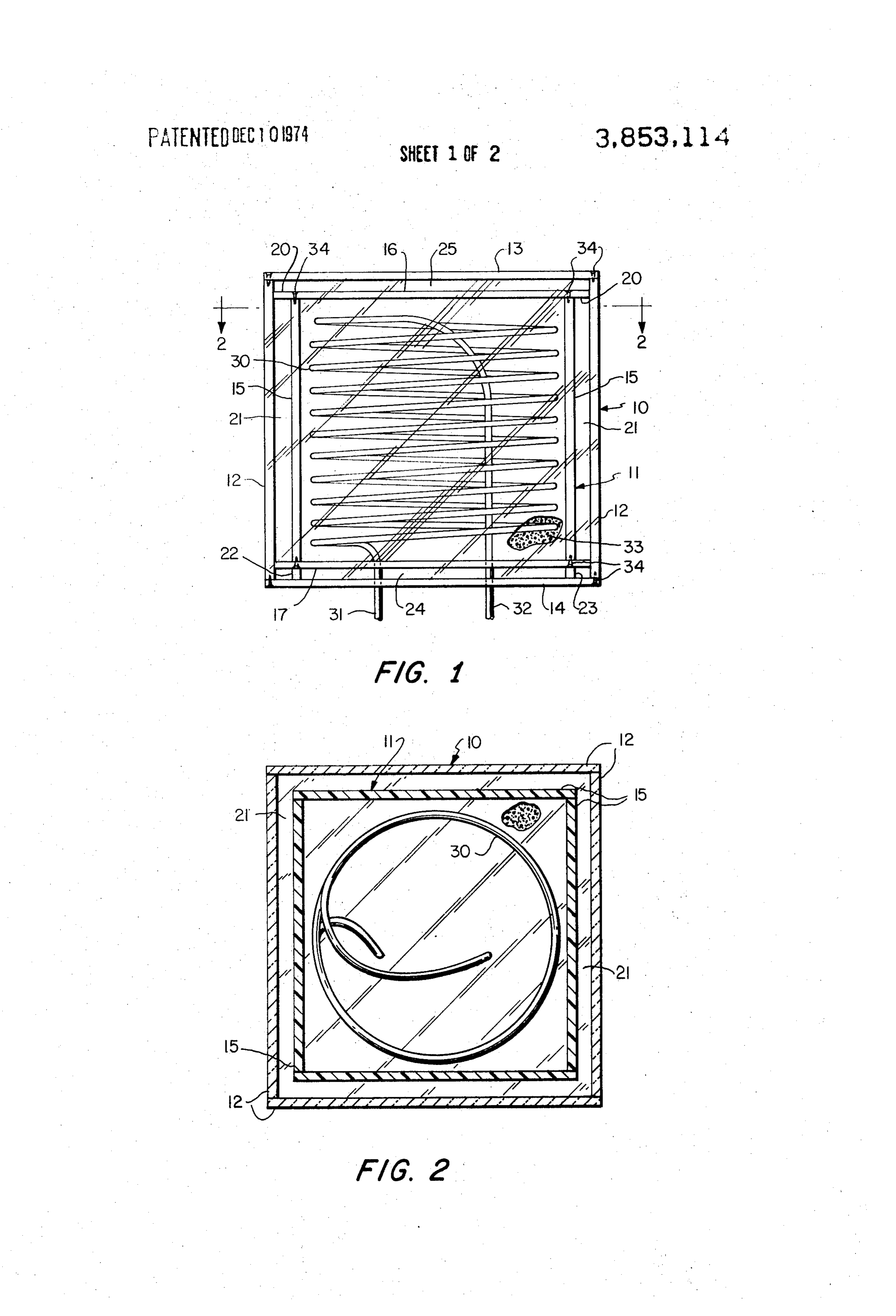
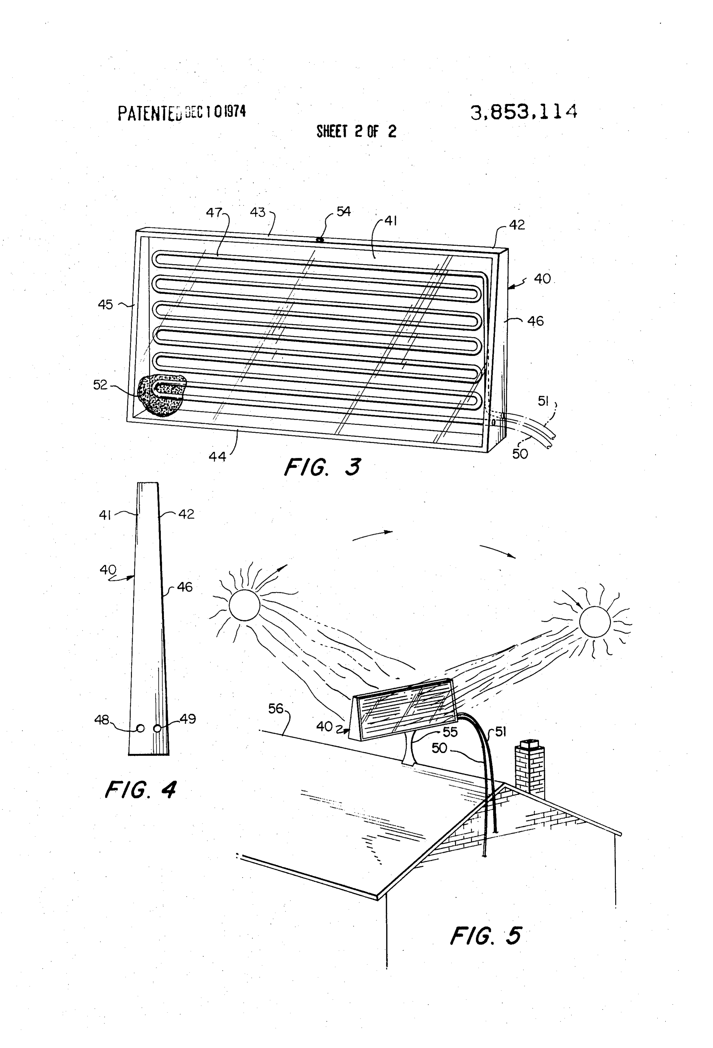
This invention relates to devices for utilizing solar en cient of thermal conductivity and, in addition, is trans ergy and, particularly, to solar energy energy absorbing parent to solar radiation. It will be noted that the term devices for elevating fluid temperature. "Plexiglass' is a registered trademark of Rohm & Haas An object of this invention is to provide an improved Co. signifying an acrylic resin plastic sheet which is a solar heating apparatus which contains a closed fluid thermoplastic, colorless material which transmits all system and heat absorbing material and which is partic colors of the visible spectrum with about 91 to 92 per ularly well adapted to be added to an existing structure O cent efficiency, and is inert to many chemicals. Walls such as a private home. 12 can be made of glass panels to better withstand the An additional object is to provide an absorber which effects of exposure to the elements, but Plexiglass or is highly efficient in an environment of relatively low walls 12 can the like and alternatively be used. While not all of the 15 need be transparent, it will be apparent temperatures, such as the northern United States, and that at least two walls thereof must be transparent and, which minimizes heat losses due to conduction and 15 additionally, they should be adjacent ones of the walls convection.
Briefly described, the invention is directed to a rect in Contained the two boxes.
within interior box 11 is a helical arrange angular box having at least two transparent walls, the ment of tubing 30 having inlet and outlet connecting box having contained therein a convoluted or serpen tubing portions 31 and 32 which pass through walls 17 tine arrangement of tubing surrounded by particulate 20 and 14 of the two boxes. Surrounding helix 30 and sub heat absorbing material. Conduit means is provided to stantially filling the interior interconnect the tubing in the box with an external uti of loose particulate materialof33 box 11 is an aggregation lization device such as a remotely located heat ex absorb solar energy and retain thewhich heat is employed to derived there changer. A second box can be provided surrounding from. For simplicity, most of the particulate the first and spaced therefrom in all directions to estab 25 omitted from FIGS. 1 and 2 so that the coilmaterial is and wall lish a dead air space therebetween. The second box has transparent walls coinciding with the first to permit the structure
will not be obscured.
example of the specific construction tech entry of radiation energy. Means for mounting the de nique, the interior box can be contructed of sheets of vice, such as on the roof of a house, can also be pro one quarter inch Plexiglass, each approximately 3 feet vided. 30 square, connected together as illustrated using In order that the manner in which the foregoing and other objects are attained in accordance with the in threadedadhesive.
fasteners as shown at 34 or using a suitable
In any event, it is desirable to apply adhesive vention can be understood in detail, particularly advan to all joints to prevent undesirable air circulation be tageous embodiments thereof will be described with tween cavities. The outer box can be formed from simi reference to the accompanying drawings, which form 35 lar and slightly larger sheets of glass or Plexiglass and a part of this specification, and wherein: similarly fastened and adhered together so that the FIG. 1 is a side elevational of one embodiment of the spaces 21, 24 and 25 are essentially sealed air spaces invention; and, therefore, highly insulating. The spaces can conve FIG. 2 is a plan view, in partial section, along the niently be about one half inch between parallel sheets.
FIG. 3 is a perspective view of a further embodiment Helix 30 can be formed from three eighth inch cop of the invention; per tubing and, in a box of the dimensions described, FIG. 4 is an end view of the embodiment of FIG. 3; about 160 feet of tubing can be employed, resulting in and a substantial volume of fluid within the interior cham FIG. 5 is a diagram showing, schematically, the man 45 ber at any single time. The tubing should, of course, be ner in which the apparatus of FIGS. 3 and 4 can be em coiled with no kinks to impede fluid flow. ployed. The particulate material preferably includes perlite, Referring now to the drawings in detail, it will be seen magnetite and lampblack, the proportions being ap that FIG. 1 shows an apparatus having an exterior box proximately 8:1:1, respectively, by volume. This partic indicated generally at 10 and an interior box indicated 50 ular mixture of materials has been found to be quite generally at 11. The exterior box is composed of side suitable in that it absorbs energy from solar radiation walls 12, an upper wall 13 and a lower wall 14 and the and reaches an elevated temperature which effectively interior box includes side walls 15, an upper wall 16 heats the liquid within helical conduit 30. A more con and a lower wall 17. Upper wall 16 of the interior box 55 venient measure is by weight, the proportions then 11 is provided with marginal extension portion 20 being 100 lb. of perlite mixed with 50 lb. of magnetite which extend outwardly beyond side walls 15 and and 25 lb. of lampblack. This mixture has been found contact the interior surfaces of walls 12 to act as spac to be particularly effective in gathering and holding ers, forming a gap 21 between walls 15 and walls 12 on heat.
all sides of the interior box. These constitute dead air 60 As will be recognized, the apparatus of FIGS. 1 and spaces for insulating purposes. Support spacers 22 and 2 is designed for use in conjunction with a remote heat 23 are provided between lower walls 17 and 14 so that exchanger of any conventional type and that the system the interior box is upwardly spaced from the lower wall can employ a pump to circulate any fluid, such as wa of the exterior box, providing an additional dead air ter, through tubing 30 and to the exchanger. Thus, heat space 24 between the box bottoms. Spacers 22 and 23 65 absorbed by particulate material 33 is transferred to are dimensioned so that the upper walls 13 and 16 of the tubing and to the fluid contained therein, which the boxes are spaced apart, creating a dead air space fluid is pumped to the other exchanger to elevate the 25. temperature at that location. If desired, a state change
Page 5
of the fluid can also be employed, but the structure as heat a fluid comprising shown is not significantly altered thereby. a first internal container having transparent substan Turning now to FIGS. 3-5, the embodiment disclosed tially vertical side walls and top and bottom walls therein includes a rectangular box 40 having transpar defining a closed interior cavity; ent faces 41 and 42 which are transparent and which a second external container having transparent verti constitute, to a significant extent, the largest surfaces cal side walls and top and bottom walls, of the unit. A frame is in edge-to-edge contact with the walls of said external container being larger than faces 41 and 42 and includes a top member 43, a bot the walls of said first container; tom member 44 and substantially identical end mem means for supporting said internal container within bers 45 and 46. It will be observed in the specific em said external container with the walls of said con bodiment shown in FIGS. 3-5 that the end members tainers in substantially parallel, spaced relationship are tapered so that the top is narrower than the bottom, defining air-containing spaces therebetween; providing a slight slope to surfaces 41 and 42. fluid conducting means contained within said inter Contained within housing 40 is a sinuous array of nal container in heat exchanging relationship with tubing 47, the end portions of which exit through open 15 the interior cavity thereof; ings 48 and 49 and form, or are connected to conduits conduit means passing through one of said walls and 50 and 51 which are connected to a remote heat ex connecting to said fluid conducting means for con changer in a manner similar to that described with ref ducting heated fluid to a remote location; and erence to FIGS. 1 and 2. particulate radiation and heat absorbing material The interior cavity of housing 40 is substantially filled contained within said internal container, surround with particulate material 52 which surrounds tubing 47 ing said fluid conducting means and substantially and performs a heat absorbing and transfer function filling said interior cavity. similar to that described in connection with the em 2. An apparatus according to claim wherein said bodiment of FIGS. and 2. The same mixture of the particulate material comprises an admixture of perlite, same materials can be employed. As shown in FIG. 5, 25 magnetite and lampblack, the components being pres unit 40 can be mounted on a standard 55 on the roof ent in relative ratio of 4:2:1, by weight. 56 of a building with conduits 50 and 51 connected in 3. An apparatus for utilizing solar radiation energy to any convenient fashion to the equipment in the build heat a fluid comprising ing. Unit 40 can be initially rotatably adjusted so that a box having a plurality of walls joined at their edges the sides are exposed to various positions of the sun as 30 to define a polygon enclosing an interior volume, illustrated in FIG. 5. The unit is relatively small and light and can clearly be easily mounted on an existing two of said walls being significntly larger than the re Structure. maining walls and being on opposite sides of said Typical dimensions for the unit of FIGS. 3-5 employ box forming major faces thereof, rectangular glass panels measuring 4 x 8 feet for faces 35 said two walls being transparent to visible radiation; 41 and 42 with end members 45 and 46 being approxi mately 4 feet tall and tapering from a 3 inch dimension means for supporting the box such that said major at the top to a 6 inch dimension at the bottom. An faces are substantially vertical; opening 54 can be provided in top member 43 to ad a sinuous array of tubing disposed in a plane substan the particulate material. 40 tially parallel to said major faces within said inte While certain advantageous embodiments have been rior volume, chosen to illustrate the invention, it will be understood particulate radiation and heat absorbing material by those skilled in the art that various changes and contained within said interior volume and sur modifications can be made therein without departing rounding said tubing; and from the scope of the invention as defined in the ap 45 fluid conduit means passing through one of said walls pended claims. and connected to said tubing for conducting fluid What is claimed is: thereto.
1. An apparatus for utilizing solar radiation energy to sk k x ck k
Provenance
- Collection
- Cited prior art
- Original PDF
- patentimages.storage.googleapis.com →
- Filed
- 1974-03-11
- Pages
- 5
- Method
- pdftotext (the PDF's own text layer) + pdftoppm 300dpi page scans
- Source
- Google Patents bibliographic record
- Granted
- 1974-12-10
- Inventors
- G Gaydos
- Transcribed from
- patentimages.storage.googleapis.com →