patent · US3412728
Solar heating equipment
26 November 1968
Page 1
Drawing sheet — no readable text.
Page 2
United States Patent Office Patented Nov. 26, 1968
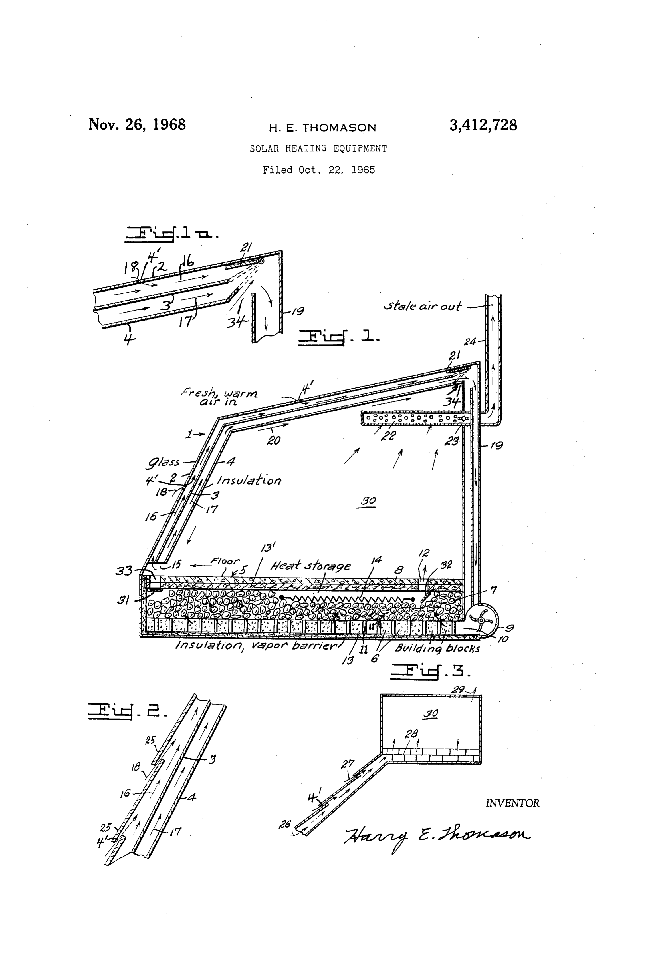
it to blocks 6 through distributor manifold 10, Such air 3,42,728 passing out into material 7 through cracks 11 between
SOLAR HEATING EQUIPMENT the blocks. The air may pass out of the storage mate Harry E. Thomason, District Heights, Md. rial through one or more holes or registers 12. Insula (6802 Walker Mill Road S.E., Washington, D.C. 20027) tion 13 is preferably provided for the walls and floor Filed Oct. 22, 1965, Ser. No. 501,967 of the heat storage bin.
20 Cairns. (C. 126-270) If desired an auxiliary heat source 14 may be provided and dampers 31, 32 may be provided to close or open
ABSTRACT OF THE DISCLOSURE passageways 33, 2 respectively.
Air passing through passageway 12 into area 30 may
Solar heat collector 1 on a building warms air and the 10 leave through passageway 15 back to heat collector 1, or warmed air is circulated by blower 9 to warm heat may leave by passageway 34 for recirculation by blower storage material 7 and the building space 30. Stale air 9, or may leave the building by passageway 22, 24, or goes out at 22 and fresh, prewarmed air, enters the sys may leave area 30 by two or more of these passageways tem at 4. depending on adjustment of the various dampers 21, 23.
31, 32, as will be explained more fully hereinafter.
This invention relates to equipment to collect and Convection currents of warm air are illustrated at 16, utilize Solar heat, in a building, for example. 17, 18, 20.
The building to be warmed, and in which the air is to Operation:
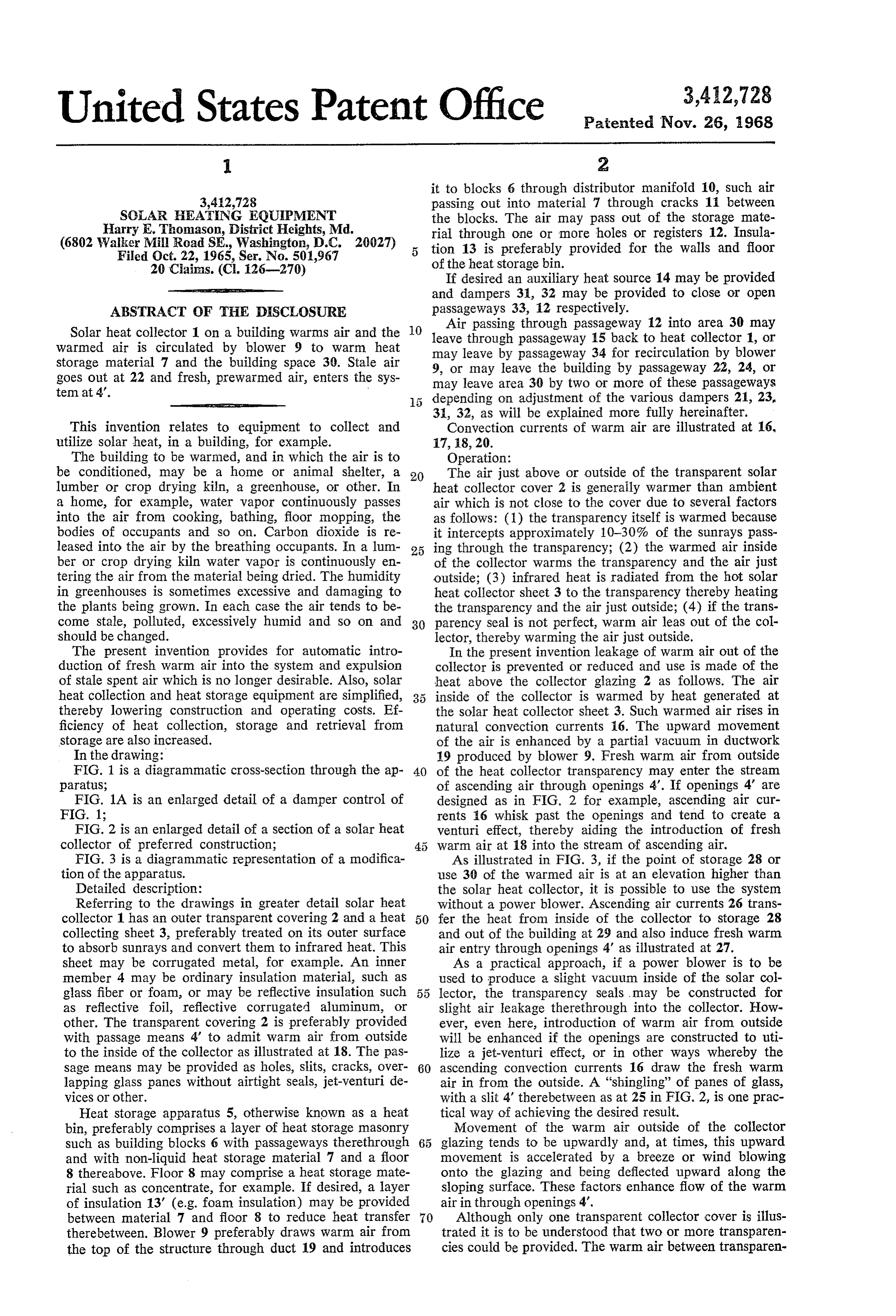
be conditioned, may be a home or animal shelter, a 20 The air just above or outside of the transparent solar lumber or crop drying kiln, a greenhouse, or other. In heat collector cover 2 is generally warmer than ambient a home, for example, water vapor continuously passes air which is not close to the cover due to several factors into the air from cooking, bathing, floor mopping, the as follows: (1) the transparency itself is warmed because bodies of occupants and so on. Carbon dioxide is re it intercepts approximately 10-30% of the sunrays pass leased into the air by the breathing occupants. In a lum 25 ing through the transparency; (2) the warmed air inside ber or crop drying kiln water vapor is continuously en of the collector warms the transparency and the air just tering the air from the material being dried. The humidity outside; (3) infrared heat is radiated from the hot Solar in greenhouses is sometimes excessive and damaging to heat collector sheet 3 to the transparency thereby heating the plants being grown. In each case the air tends to be the transparency and the air just outside; (4) if the trans come stale, polluted, excessively humid and so on and 30 parency seal is not perfect, warm air leas out of the col should be changed. lector, thereby warming the air just outside. The present invention provides for automatic intro In the present invention leakage of warm air out of the duction of fresh warm air into the system and expulsion collector is prevented or reduced and use is made of the of stale spent air which is no longer desirable. Also, solar heat above the collector glazing 2 as follows. The air heat collection and heat storage equipment are simplified, inside of the collector is warmed by heat generated at thereby lowering construction and operating costs. Ef the solar heat collector sheet 3. Such warmed air rises in ficiency of heat collection, storage and retrieval from natural convection currents 16. The upward movement storage are also increased. of the air is enhanced by a partial vacuum in ductwork In the drawing: 19 produced by blower 9. Fresh warm air from outside FIG. 1 is a diagrammatic cross-section through the ap 40 of the heat collector transparency may enter the stream paratus; of ascending air through openings 4'. If openings 4 are FIG. 1A is an enlarged detail of a damper control of designed as in FIG. 2 for example, ascending air cur FIG. 1; rents 16 whisk past the openings and tend to create a FIG. 2 is an enlarged detail of a section of a solar heat venturi effect, thereby aiding the introduction of fresh collector of preferred construction; warm air at 18 into the stream of ascending air. FIG. 3 is a diagrammatic representation of a modifica As illustrated in FIG. 3, if the point of storage 28 or tion of the apparatus. use 30 of the warmed air is at an elevation higher than Detailed description: the solar heat collector, it is possible to use the system Referring to the drawings in greater detail Solar heat without a power blower. Ascending air currents 26 trans collector 1 has an outer transparent covering 2 and a heat 50 fer the heat from inside of the collector to storage 28 collecting sheet 3, preferably treated on its outer Surface and out of the building at 29 and also induce fresh warm to absorb sunrays and convert them to infrared heat. This air entry through openings 4' as illustrated at 27. sheet may be corrugated metal, for example. An inner As a practical approach, if a power blower is to be member 4 may be ordinary insulation material, such as used to produce a slight vacuum inside of the solar col glass fiber or foam, or may be reflective insulation such lector, the transparency seals may be constructed for as reflective foil, reflective corrugated aluminum, or slight air leakage therethrough into the collector. How other. The transparent covering 2 is preferably provided ever, even here, introduction of warm air from outside with passage means 4 to admit warm air from outside will be enhanced if the openings are constructed to uti to the inside of the collector as illustrated at 18. The pas lize a jet-venturi effect, or in other ways whereby the sage means may be provided as holes, slits, cracks, over 60 ascending convection currents 16 draw the fresh warm lapping glass panes without airtight seals, jet-venturi de air in from the outside. A “shingling' of panes of glass, vices or other. with a slit 4 therebetween as at 25 in FIG. 2, is one prac Heat storage apparatus 5, otherwise known as a heat tical way of achieving the desired result. bin, preferably comprises a layer of heat storage masonry Movement of the warm air outside of the collector such as building blocks 6 with passageways therethrough 65 glazing tends to be upwardly and, at times, this upward and with non-liquid heat storage material 7 and a floor movement is accelerated by a breeze or wind blowing 8 thereabove. Floor 8 may comprise a heat Storage mate onto the glazing and being deflected upward along the rial such as concentrate, for example. If desired, a layer sloping surface. These factors enhance flow of the warm of insulation 13' (e.g. foam insulation) may be provided air in through openings 4.
between material 7 and floor 8 to reduce heat transfer 70 Although only one transparent collector cover is illus therebetween. Blower 9 preferably draws warm air from trated it is to be understood that two or more transparen the top of the structure through duct 19 and introduces cies could be provided. The warm air between transparen
Page 3
cies would preferably be allowed to ascend, as convection 8. Apparatus as in claim wherein said heat storage currents, and then pass on to storage or a point of use. means comprises a layer of masonry blocks providing Warm air from the outside would be permitted to enter air passageways therethrough and air passages therefrom, through slits or other openings in the outer transparency heat storage material above said layer of masonry blocks in a manner similar to that described for one transpar 5 and through which air passes in heat-exchange relation ency. ship with said heat storage material, and a passageway For some purposes constant circulation of air through leading outwardly from said heat storage means. the system and interior 30 of the building is desirable, e.g. 9. Apparatus as in claim 1 wherein said solar heat col lumber or crop drying. In other instances it is desirable lector comprises an outer transparency, solar energy ab to bypass the interior 30 and circulate air from the top sorbing material below said transparency, and a passage of solar collector 1 to heat storage apparatus 5 and di O way for circulation of air to remove heat trapped under rectly back to the solar collector. As exemplary of such said transparency, said passage means extending from a operation the interior 30 may be warm enough but addi location immediately outside of said transparency to said tional heat is to be stored for later use. In such instance passageway to admit air to said collector. damper 31 may be opened, or partially opened, and 10. Apparatus as in claim 9 wherein said solar energy damper 32 may be closed, or partially closed, to reduce absorbing material comprises an outer sheet with an outer or temporarily eliminate circulation through interior 30. energy absorbing surface, and an inner sheet having a Thus the air is returned from the storage apparatus di reflective surface.
rectly to the solar heat collector through opening 33. 11. Apparatus as in claim 10 wherein air is circulated Some of the Solar energy entering through transparency between said outer sheet and said inner sheet. 2 and warming collector sheet 3 warms the air therebe 12. A solar heat collector having an upper edge and tween which rises at 16. Some of the heat warms air be a lower edge, an inlet adjacent to the lower edge for in tween sheets 3 and 4 and this warmed air rises at 17. Some troduction of air to be heated and an outlet adjacent to of the heat warms sheet 4 and, at least to a limited ex the upper edge for heated air discharge, an outer trans tent, the heat gets through sheet 4, even if it is insulating 25 parency, solar energy absorbing material below said trans in nature. This, in turn, warms air inside the building. parency, a passageway for circulation of air to remove This heated air rises as illustrated at 20. heat trapped under Said transparency, and passage means Warm sheet 4 also radiates some infrared heat to the leading from a location immediately outside of said trans interior of the building. The amount of heat so radiated parency and spaced upwardly from the lower edge and may be minimized, if desired, by a high degree of heat 30 said inlet to introduce to said passageway fresh pre insulating reflectivity of sheet 4, or by glass fiber, foam warmed air rising from said collector. or other insulation, or by both reflective and fiber or foam 13. Apparatus as in claim 12 wherein said solar energy insulation. Or, the amount of heat radiated may be in absorbing material comprises an outer sheet with an outer creased by reducing the insulating value of the material energy absorbing surface, and an inner sheet having a or by completely eliminating sheet 4 and all insulating 35 reflective surface.
materials. 14. Apparatus as in claim 13 wherein air is circulated Damper 21 may be moved to any desired position to between said outer sheet and said inner sheet. allow air to flow only from space 30, through opening 15. Solar heating apparatus comprising a building 34, to duct 19, or from space 30 plus the space between structure, a solar heat collector, having a lower edge and sheets 3 and 4, or from these spaces plus the space be 40 an upper edge, mounted in an inclined position on said tween transparency 2 and sheet 3. building and facing in a direction to intercept Solar in I claim: solation, said solar heat collector comprising an inlet ad 1. Solar heating apparatus comprising a solar heat col jacent to the lower edge for introduction of air to be lector having an upper edge and a lower edge, an inlet warmed and an outlet adjacent to the upper edge for adjacent to the lower edge for air to be heated and an warmed air discharge, a transparent outer covering with outlet adjacent to the upper edge for heated air discharge, 45 solar heat collecting means therebeneath, air in said solar heat Storage means, conduit means for circulation of air heat collector being in contact with said heat collecting serially through said solar heat collector and through said means to thereby warm said air whereby said warmed heat storage means, passage means leading from an area air ascends through said inclined solar heat collector, heat immediately outside the solar heat collector, and spaced 50 storage means, means to circulate the warmed air from upwardly from the lower edge and said inlet, to intro the outlet from said solar heat collector to said heat duce fresh partially warmed air into said solar heat col storage means for storing a portion of the heat from the lector, paratus.
and vent means to expel stale air from said ap warmed air and to circulate the air to the interior of the building structure and back to the inlet to said solar heat 2. Apparatus as in claim 1 and walls enclosing a space 55 collector, the air, while passing through the building struc to be heated or ventilated or both, and conduit means ture, warming and driving off liquids or vapors from the for circulation of air from said heat storage means to interior or contents of the building structure in the form said space and to said solar heat collector. of vapor in the air, means to remove a portion of the 3. Apparatus as in claim 1 and means to bypass cir vapor and air from the building structure, and means to culation of at least a portion of the air directly from said 60 introduce fresh makeup air to the system from an area heat storage means to said Solar heat collector. immediately above the transparent covering and spaced 4. Apparatus as in claim 1 and power operated means upwardly from the lower edge of the heat collector to to circulate air through said solar heat collector and said replace the removed air.
heat storage means. 16. Apparatus as in claim 15 wherein said solar heat 5. Apparatus as in claim 1 wherein said passage means 65 collector comprises a first sheet of material having an to introduce fresh air into said solar heat collector com upper heat-receiving surface, a heat reflective sheet below prises passage means leading from a location adjacent to said first sheet with an air space therebetween, air cir an outer surface of said heat collector whereby the fresh culating between said sheets to remove a portion of the air being introduced is pre-warmed prior to and as it heat from said first sheet with a portion of the heat enters the solar heat collector. warming said second sheet, said second sheet radiating 6. Apparatus as in claim 2 wherein said vent means to 70 heat to the interior of said building structure to help expel stale air comprises conduit means leading from warm the interior, or contents, to help drive of liquids said space to the exterior of said space. or vapors therefrom into the circulating air. 7. Apparatus as in claim 6 and damper means in said 17. Apparatus as in claim 15 wherein said solar heat vent means to control the rate of stale air expulsion. 75 collecting means comprises a sheet of material having an
Page 4
upper heat-receiving surface and a lower heat radiating heat storage means comprising a concrete-like material, surface to radiate heat to the interior of the building said concrete-like material being in heat-exchange rela structure to help warm the interior. tionship with said stone-like material such that the con 18. Solar heating apparatus comprising a solar heat crete-like material serves as additional heat storage ma collector, heat storage means, conduit means for circula 5 terial.
tion of air through said solar heat collector and said heat 20. Apparatus as in claim 9 wherein said concrete storage means, passage means to introduce fresh air into like material comprises a floor for space to be heated said solar heat collector, vent means to expel stale air above said heat storage material. from said apparatus, said heat storage means comprising References Cited a layer of masonry blocks providing air passageways there 0.
through and air passages therefrom, heat storage material UNITED STATES PATENTS above said layer of masonry blocks and through which 246,626 9/1881 Morse ------------- 126-270 air passes in heat-exchange relationship with said heat 430,762 6/1890 Taylor ----------- 126-270 X storage material, a passageway leading outwardly from 2,484,127 10/1949 Stelzer. said heat storage means, said heat storage material com 5 2,529,621 11/1950 Mayo ---------------- 237-1 prising stone-like material, a top for said heat storage 2,680,565 6/1954 Lof ------------------ 237 means comprising a concrete-like material, and insulation means between said stone-like and said concrete-like ma FOREIGN PATENTS terials. 1,204,560 8/1959 France. 9. Apparatus as in claim 18 wherein said heat storage 20 material comprises stone-like material, and a top for said CHARLESJ. MYHRE, Primary Examiner.
Provenance
- Collection
- Cited prior art
- Original PDF
- patentimages.storage.googleapis.com →
- Filed
- 1965-10-22
- Pages
- 4
- Method
- pdftotext (the PDF's own text layer) + pdftoppm 300dpi page scans
- Source
- Google Patents bibliographic record
- Granted
- 1968-11-26
- Inventors
- Harry E Thomason
- Transcribed from
- patentimages.storage.googleapis.com →