patent · US6065284
Refractory heat transfer module
23 May 2000
Page 1 — bibliographic record
United States Patent 19 11 Patent Number: 6,065,284 Horner et al. (45) Date of Patent: May 23, 2000 54 REFRACTORY HEAT TRANSFER MODULE Malloy, et al., “Trade Studies on Integrated Solar Upper Stage (ISUS) Systems", IECEC Paper No. AP-399, ASME 75 Inventors: Mervyn H. Horner, Del Mar; Holger (1995), pp. 749–753.
H. Streckert, Rancho Santa Fe, both of
Calif. Westerman, “Solar Bi-Model: The Challenge of Developing Advanced Space Power and Propulsion Technology', 73 Assignee: General Atomics, San Diego, Calif. IECEC Paper No. AP-400, ASME (1995), pp. 737-742. Kennedy, et al., “Mission Applications of an Integrated Solar 21 Appl. No.: 09/027,361 Upper Stage (ISUS)”, IECEC Paper No. AP-401, ASME 22 Filed: Feb. 20, 1998 (1995), pp. 731–736.
Related U.S. Application Data Primary Examiner-Charles G. Freay 60 Provisional application No. 60/053,775, Jul. 25, 1997. Attorney, Agent, or Firm Fitch, Even, Tabin & Flannery (51) Int. Cl. ................................................. G21D 1700 57 ABSTRACT 52 U.S. C. ... . 60/203.1; 60/641.15; 126/680;
244/173 An Integrated Solar Upper Stage receiver is shown for 58 Field of Search ................................ 60/200. 1, 203.1, efficiently transferring heat from concentrated Solar flux to 60/641.15, 641.8; 244/169, 173, 172; 126/680, an interior Surface of an annular structure having a plurality 681, 682 of parallel passageways through which hydrogen gas flows
and is heated to a high temperature to Serve as a propellant in order to raise the ISUS from a low earth orbit to a
body of refractory material, Such as graphite, in which each 3,594,803 7/1971 Pucillo .................................... 343/720 of the hydrogen flow passageways is lined with a thin tube 3,843,896 10/1974 Rason et al. ..... ... 310/4 of wrought rhenium metal. The exterior surfaces of the 4,482,837 11/1984 Koizumi et al. . ... 378/144 receiver are similarly clad with wrought rhenium, or coated 4,528,978 7/1985 Robinson ......... ... 60/641.8 with CVD rhenium, to prevent evaporation of graphite at 4,781,018 11/1988 Shoji ........ ... 60/641.8 4,876,854 10/1989 Owens ......... ... 60/641.8 high temperatures in Outer Space. Inlet and outlet manifolds 5,113,659 5/1992 Baker et al. ... ... 60/641.8 which communicate with the rhenium-lined passageways 5,459.996 10/1995 Malloy et al. ......................... 60/200.1 are also constructed of wrought rhenium metal and Serve to
OTHER PUBLICATIONS
totally isolate the hydrogen from the graphite heat Sink material So as to avoid chemical reaction therebetween.
Streckert, et al., “Integrated Solar Upper Stage Alternate Hydrogen gas from a cryogenic Source is thus heated and Receiver”, IECEC 1997 Conference, Jul. 28, 1997. expanded, Serving as a propellant when exhausted through a Miller, et al., “Design and Fabrication of a High Tempera nozzle.
ture Solar Receiver Cavity", IECEC Paper No. AP-398,
ASME (1995), pp. 755–761. 19 Claims, 3 Drawing Sheets
COMTROL
SYSTEM
HYDROGEN
EXHAUS
CRYOGENIC
H, SOURCE
Page 2
Drawing sheet — no readable text.
Page 3
Drawing sheet — no readable text.
Page 4
Drawing sheet — no readable text.
Page 5
REFRACTORY HEAT TRANSFER MODULE internal passageways through which a gas, Such as hydrogen, can be allowed to slowly flow in order to raise its
This application claims priority from U.S. Provisional temperature to above 2000 K and increase its pressure Application Ser. No. 60/053,775 filed Jul. 25, 1997 entitled enabling it to be effectively used as a propellant by discharge Refractory Heat Transfer Module, the disclosure of which is through an appropriate nozzle. By lining these passageways incorporated herein by reference. with boundary material in the form of wrought refractory This invention relates to a refractory heat transfer module metal, Such as wrought rhenium(Re), an effective barrier is for heating a gas Such as hydrogen and to methods for provided having good thermal conductivity. making Such modules. More particularly, the invention Because it is also necessary to prevent the graphite or relates to a module for use in Space in combination with a other refractory material receiver that is heated to a high concentrator for Solar flux that would focus concentrated temperature from evaporating in the extremely low preSSure Solar rays upon the module which would serve as a high environment at the fringes of the earth's atmosphere, exter temperature heat Sink particularly designed to raise the nal cladding for the receiver is also required. It is found that temperature of hydrogen gas, from a cryogenic Source of wrought rhenium sheeting may also be used to totally hydrogen, So that Such heated gas Stream can be discharged 15 encapsulate the receiver by its appropriate joinder to ends of through an exhaust nozzle to create Space propulsion. the passageway-providing rhenium liners that protrude from
BACKGROUND OF THE INVENTION
the graphite body receiver. For example, fusion bonding of
Sections of Re sheeting or alternative methods of encapsu
The Integrated Solar Upper Stage (ISUS) is an advanced lating the high temperature refractory material receiver, Such orbital transfer vehicle which is designed to be capable of as chemical vapor deposition (CVD) coating, may be used generating electrical power and providing thrust which that are compatible with Such wrought rhenium passageway enables it to efficiently transfer payloads from low earth liners.
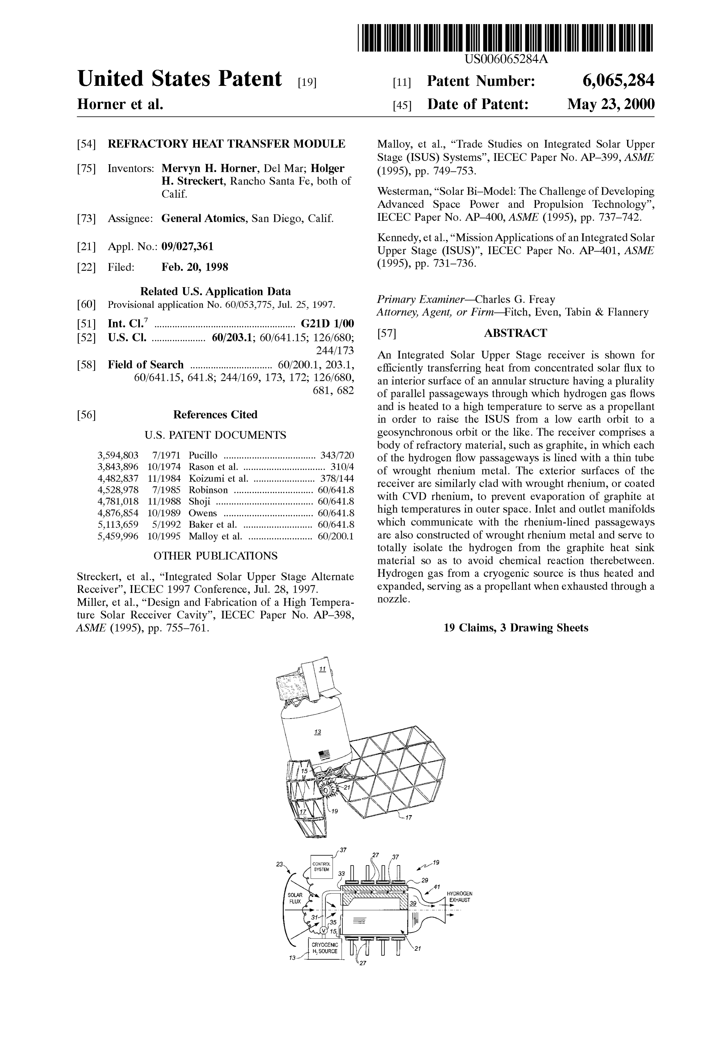
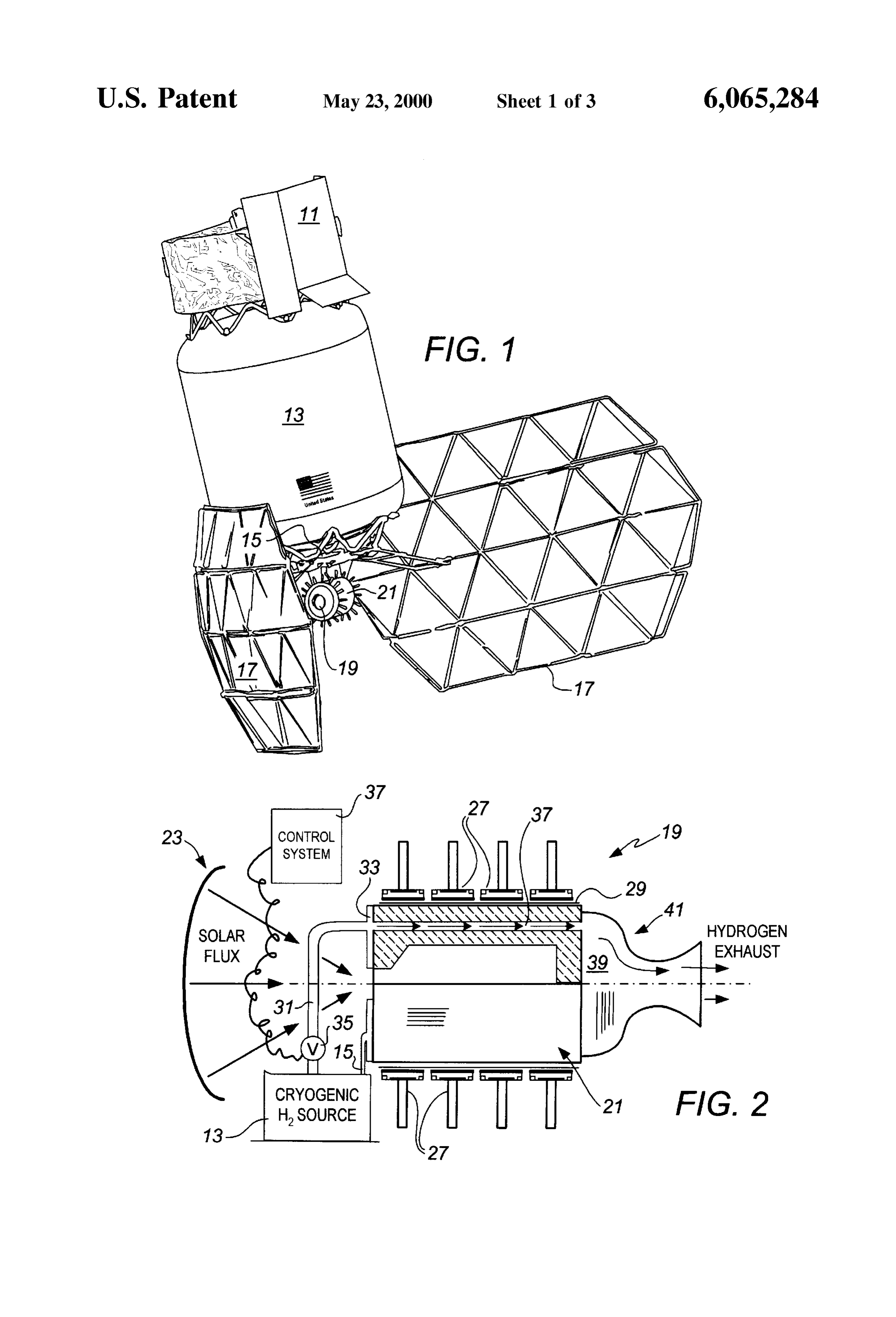
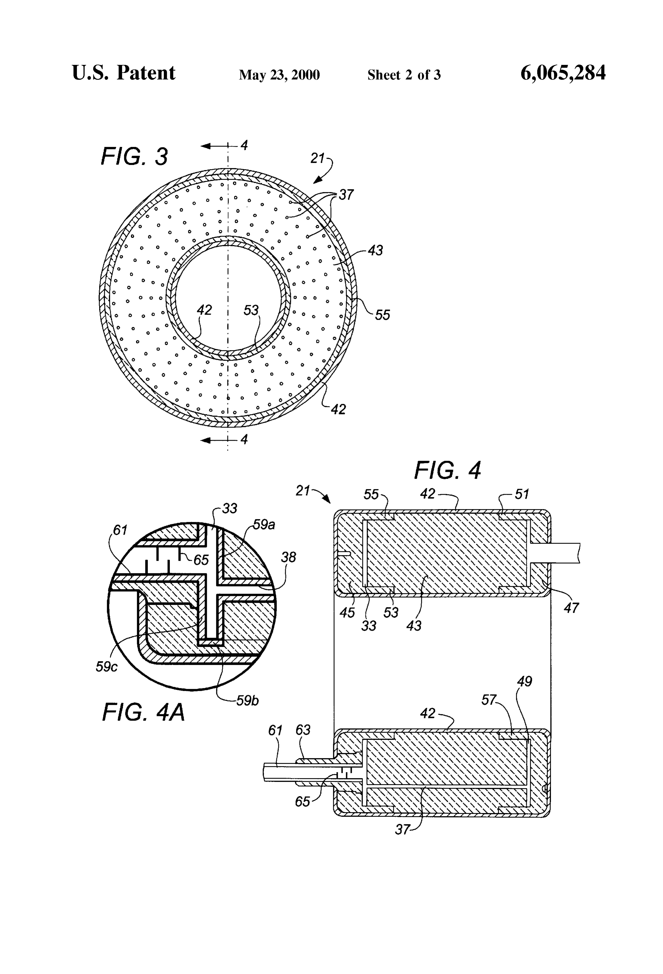
orbits to higher Molniya or geosynchronous orbits. A Series BRIEF DESCRIPTION OPTHE DRAWINGS of papers were published in 1995 reporting upon the then 25 current design of the ISUS, i.e. IECEC 95 Papers Nos. FIG. 1 is a diagrammatic perspective View showing an AP-398, AP-399, AP-400 and AP-401 (ASME 1995). U.S. example of an ISUS vehicle which incorporates a propulsion Pat. No. 5,459,996 discloses a different type of Solar rocket device embodying various features of the present invention. designed to burn propellant, and U.S. Pat. No. 5,113,659 FIG. 2 is a Schematic drawing showing the propulsion discloses a receiver for use in Space vehicle operations device of FIG. 1 including the annular receiver, the cryo designed to use Solar energy to heat Sodium in heat pipes. genic hydrogen Supply tank and the Solar concentrator. The disclosures of these two patents and these four papers FIG. 3 is a Schematic Sectional view through an annular are incorporated herein by reference. receiver exemplifying the type depicted in FIG. 2. The ISUS vehicle, as it orbits earth in a low orbit, is designed to collect Solar flux via a tracking receptor System 35 3. FIG. 4 is a sectional view taken along line 4-4 of FIG. and focus the flux upon a concentrator, providing a concen FIG. 4A is a fragmentary enlarged view of a portion of trated Source of heat. This heat Source is to be used to drive
FIG. 4 shown in circular outline.
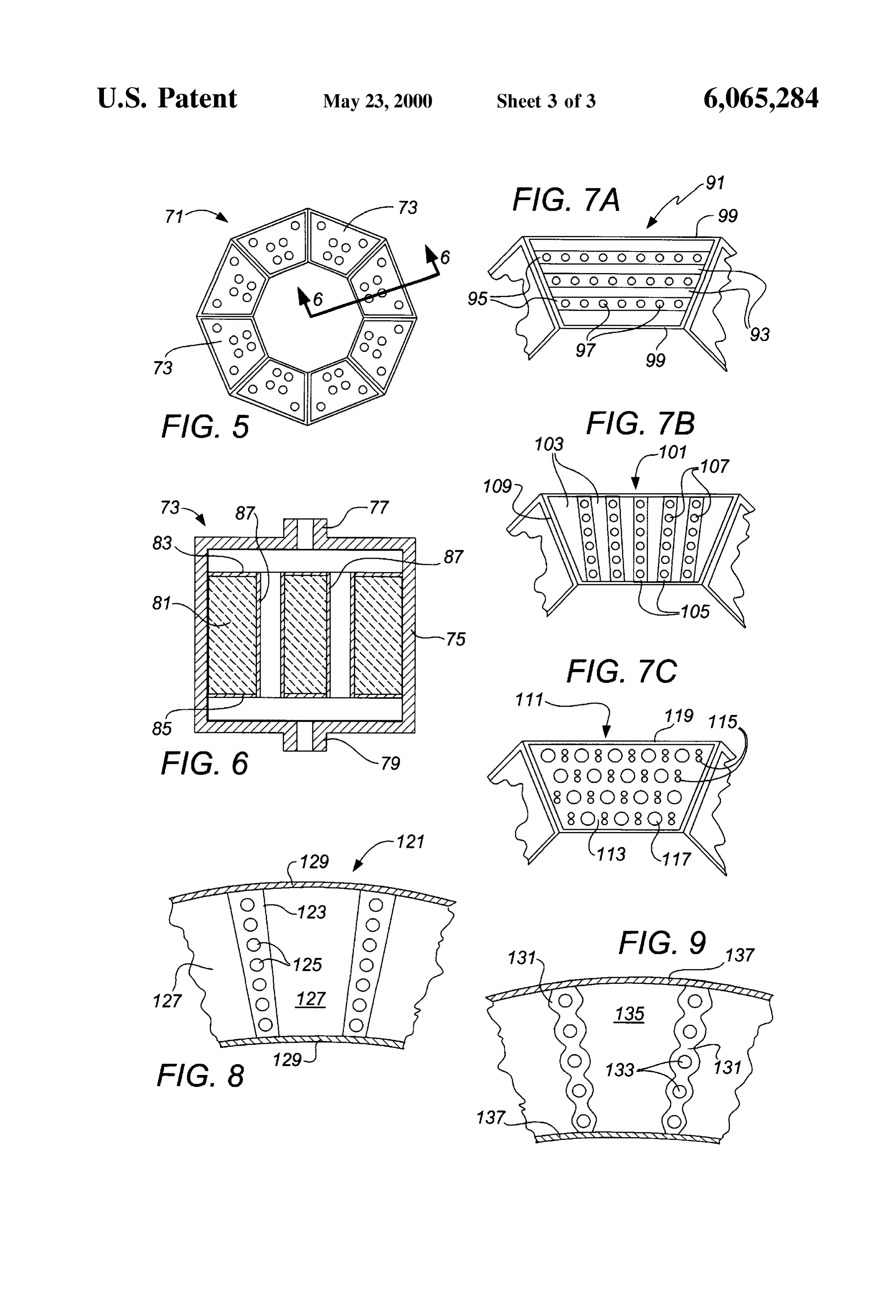
the temperature of a receiver up to about 2500 K. A valve arrangement is provided to appropriately Supply hydrogen FIG. 5 is a schematic view similar to FIG. 3 showing an gas from a cryogenic Source which is caused to flow through 40 alternative polygonal annular receiver. internal passageways within the high temperature receiver FIG. 6 is a schematic sectional view taken along line 6-6 So as to heat the gas to a temperature approaching that of the of FIG. 5.
receiver itself. The heated hydrogen is then exhausted FIGS. 7A, 7B and 7C show three different modular through a nozzle So that it functions as a propellant, pro construction concepts that might be used in the FIG. 5 Viding thrust with high Specific impulse, and as Such can be 45 receiver.
employed to transfer the ISUS to a higher orbit above the FIGS. 8 and 9 are fragmentary schematic sectional views earth. The design of the ISUS also allows heat from the showing further alternative constructions for an annular receiver to be Selectively radiated to an array of thermal receiver.
energy converters, Such as thermionic converters, which can produce electrical power. The purpose of the overall design 50 DETAILED DESCRIPTION OF THE is to employ a cryogenic hydrogen Source to intermittently PREFERRED EMBODIMENT provide thrust to raise the orbit of the ISUS during approxi mately a 30-day period following launch and to thereafter as The ISUS is an advanced transfer orbital vehicle which, depicted in FIG. 1, is designed to propel a payload 11 provide electrical power for about 15 years by concentration from a low earth orbit to a higher Molniya or geosynchro of Solar flux and radiation to the thermionic converters. 55 nous orbit. In the illustrated arrangement, the payload 11 is Because of the high temperatures which are involved in appropriately mounted atop a large tank 13 of liquified gas, heating a gas Such as hydrogen Sufficiently to enable it to be Such as cryogenic hydrogen, and affixed to the opposite or efficiently used as a propellant in the far reaches of the bottom end of the tank 13 is structural framework 15 to earth's atmosphere, it is found necessary to very carefully which the remainder of the operative components are gen isolate Such hydrogen gas from the refractory material body 60 erally connected. Shown are a pair of Solar concentrator that will be used as the heat sink receiver in order to prevent assemblies 17 which may be formed of a plurality of chemical attack by hydrogen thereupon. Solutions to this triangular Segments arranged in a parabolic array and which problem are being actively Sought. would be appropriately deployed once the vehicle has SUMMARY OF THE INVENTION reached its low earth orbit. Centrally below the framework 65 a propulsion System 19 is mounted which includes an
It has been found that a receiver in the form of a body of annular collector or receiver 21 capable of Storing heat at a a refractory material, Such as graphite, can be provided with high temperature, e.g. above 2500 K. The mirrored solar
Page 6
concentrator assemblies collect Solar flux, being positioned to intermittently provide propulsive thrusts for up to about and oriented via a tracking receptor System, and may focus 30 days and to thereafter provide electrical power for up to the flux to travel into opposite ends of the receiver and onto about 15 years via the radiative coupling of the thermionic a director (not shown) which in turn directs the concentrated converters 27 to the high temperature receiver 21. To best Solar flux onto the interior Surface of the annular receiver 21. perform its desired function, the receiver 21 includes a high A concentrating mirror assembly, Such as that disclosed in heat capacity body 43 having a generally annular configu the 996 patent, may alternately be employed; either ration which provides an interior cavity to which Solar heat arrangement would be separately controlled to orient the can be effectively Supplied, as by using a Solar concentrator assembly to receive, concentrate and direct the available 23 that is part of a tracking reflector System which is Sunlight. designed to focus Solar rays on the interior walls of the The arrangement is perhaps better understood from FIG. cavity either directly or in tandem with a Secondary con 2 which Schematically illustrates the various components of Centrator.
the propulsion System 19. Depicted is a high temperature It is desired that the hydrogen vapor be heated to a high receiver 21 which is generally annular in shape having a temperature, to above 2000 K and preferably to about 2500 hollow interior with one end, e.g. the outlet end being 15 K or above; thus, the body 43 must be able to withstand still optionally closed or left open. A Solar concentrator assembly higher temperatures, preferably about 100 to 200 higher, 23, which may include the parabolic mirror panels 17, and also should have a high heat capacity So as to retain a collects rays from the Sun and concentrates them, directing substantial amount of heat when the ISUS vehicle is eclipsed them into the hollow interior of the high temperature by the earth. Thus, the body 43 should be formed from a receiver. If desired, a Secondary director (not shown) can be refractory material that is Structurally strong, has a high heat employed in tandem with the illustrated Solar concentrator capacity and a high thermal conductivity, and can function 23 to dispense the Solar flux once it has reached the interior for an extended duration at temperatures above 2500 K. of the receiver. Located about the periphery of the annular Generally, Suitable materials are considered to include receiver 21 are a plurality of thermal energy converters, Such carbon, graphite, boron, carbon-carbon composites, boron as thermionic converters 27 which are designed to create 25 carbide, niobium carbide, hafnium carbide, and boron electricity when heat is transferred to them from the heated, nitride; graphite is preferred.
high temperature receiver 21 once the vehicle has reached its Because the hydrogen propellant is chemically reactive ultimate orbit. A generally tubular shield 29 is disposed with many materials including graphite, it is considered between the Outer Surface of the high temperature receiver important that the high temperature refractory material be 21 and the thermionic converters 27 which shield serves to isolated from the hydrogen gas flowing in the passageways radiate heat back to the receiver, which it Surrounds, during 37 through the receiver to prevent it from chemically the initial period when hydrogen gas is being heated to attacking the graphite, and because many of these high heat propel the space craft to an orbit higher above the earth. capacity refractory materials have a Substantial vapor pres Once a final orbit has been reached, the shield 29 is sure at temperatures above 2500 K, it is also felt to be withdrawn, similar to the insulation sleeve in the 996 35 important that the entire receiver 21 be encapsulated to patent, So as to radiatively couple the thermionic converters prevent evaporation and contamination of optical compo 27 to the radiating exterior Surface of the high temperature nents or escape into outer Space.
receiver 21. The passageways 37 are lined with material 38 (see FIG. The cryogenic hydrogen Source, i.e. the tank 13 contain 4A) that isolates the refractory material body 43 from the ing liquified hydrogen, is connected by a conduit 31 to an 40 hydrogen, and refractory metal sheeting is preferred. It has inlet plenum 33 to the high temperature receiver So that been found that a refractory metal having a large grain hydrogen from the Source can be transferred to the receiver. microStructure, i.e. with grains having an average size above A suitable valve 35 is provided to control flow in the conduit about 30 tim, and having a random grain orientation have 31, and the valve is controlled via electrical connection to a Surprisingly excellent resistance to diffusion of hydrogen control system 37. The receiver 21 is structurally linked to 45 therethrough. It is also considered important that the refrac the tank 13 through the framework 15. As explained in more tory metal sheeting should have reasonably high tensile detail hereinafter, hydrogen vapor or gas is routed to a Strength and hardness So that relatively thin sheeting can be plurality of passagewayS 37 extending from one end to the employed as weight is an extremely important consideration other of the high temperature receiver 21 wherein the in a Space vehicle. In this respect, it is believed that the hydrogen is heated to an extremely high temperature thereby 50 refractory metal should have a tensile Strength of at least rapidly increasing its Volume. The passagewayS37 are lined about 500 MPa and should have a Rockwell A hardness of with suitable material 38 and discharge into a plenum 39 above about 50. Moreover, the refractory metal should have leading to a nozzle 41 from which the heated hydrogen a melting point above 2700 K, and suitable refractory metals discharges, creating a propulsive effect which is appropri include rhenium(Re), tungsten, molybdenum, niobium, ately directed so as to continue to raise the level of the ISUS 55 oSmium and tantalum. Wrought rhenium metal has excellent above the earth until it reaches its desired orbit, at which characteristics and can be provided with physical character time the valve 35 is closed. It is anticipated that the valve 35 istics which meets all of the foregoing criteria. Wrought will be opened intermittently whenever the receiver reaches rhenium metal has random grain orientation, and it should a target high temperature, e.g. up to about 2500 K, and then have an average grain size of about 40-60 um. The wrought closed when flow of the H cools the receiver below about 60 rhenium metal desirably also has a tensile Strength of 1800 K. Either the discharge from the nozzle can be directed between about 625 and 800 MPa and a Rockwell Ahardness so as to propel the ISUS in the desired upward direction, or between about 53 and 63. Re provides a combination of Separate vectoring rockets or jets are provided on the ISUS extremely high resistance to hydrogen diffusion together to effect the desired attitude of the ISUS before the valve 35 with good Strength and toughness, and it also has a melting is opened. 65 point of about 3450 K. Thermal conductivity is also con Details of a high temperature receiver 21 are shown sidered to be important as the purpose is of course to transfer schematically in FIGS. 3 and 4. The ISUS unit is designed heat from the graphite or other heat Sink material to the
Page 7
S 6 hydrogen gas flowing in the lined passagewayS. In this positioned in the openings in the interior manifold face respect, it is felt that thermal conductivity should be at least sheet. After electron-beam welding the ends of the liner about 30 watts per meter per Kelvin, and rhenium qualifies tubes to the face sheet 59a at one end, using an ordered, at a value of about 47.9 W/mK. Wrought rhenium of the criss-croSS type pattern to minimize any distortion of the thin foregoing physical characteristics is preferred. face sheet, the face sheet at the other end of module would For external cladding 42, a material having a melting be similarly welded into place. Next, short tubular Segments point above 2700 K again should be used. Rhenium, or bands 59b that constitute the radially inner and outer tungsten, molybdenum, niobium, osmium and tantalum, Surfaces of the manifolds are welded into place. Finally, the either in elemental form or in the form of carbide, nitride or exterior face sheets 59c having either an inlet or an outlet boride, are considered Suitable. Such cladding can be tube attached would be welded to the free edges of the short tubular band 59b to complete the two manifold assemblies.
applied by CVD, hot isostatic pressing (HIP), reaction
Sintering or pack cementation. Again, rhenium metal is 43The end caps 45, 47 are affixed to the annular main body of the receiver after the respective manifolds are preferred, and wrought rhenium is more preferred. installed, and they may be physically joined using a plurality As depicted in FIGS. 3 and 4, the receiver 21 may include of radially aligned graphite plugs that would pass through a unitary main body 43 of graphite which mates with a pair 15 one or both of the tubular flanges 53, 57 of the respective end of annular graphite caps 45, 47. A plurality of parallel caps. However, Such joinder may be unnecessary if rhenium passagewayS37 extend completely through the annular body sheet or the like is used to clad the exterior of the receiver 43 in a direction parallel to the axis thereof and Serve as and thus create a structurally confining jacket about the channels within which the gaseous hydrogen propellant is entire receiver. In this respect, CVD rhenium may be applied heated to a high temperature. The caps 45, 47 facilitate the to the exteriors of the receiver body and the end caps, creation of the inlet manifold 33 and an outlet manifold 49 because Such Surfaces do not have to Seal against hydrogen at the opposite ends of the annular body. More specifically, leakage and CVD rhenium can Serve as an effective barrier each end of the annular body is provided with an annular to prevent loSS of the refractory material by Slow evapora outer shoulder 51 and an annular inner shoulder 53, against tion. Because such CVD-applied rhenium would not physi which shoulders circular exterior and interior flanges 55, 57 25 cally join the end caps to the annular body, thus requiring of the end caps Snugly fit. Some Separate physical connection, cladding of the receiver In the illustrated embodiment, to isolate the hydrogen gas in fusion-bonded rhenium sheeting may be preferred. from the graphite, each of the passageways 37 is lined with Because the propulsion unit 19 will be subjected to large sheeting 38 of wrought rhenium having a thickness of at changes in temperature, i.e. from ambient temperatures at least about 0.1 mm and preferably having a thickness of at which it is constructed and launched into Space to operating least about 0.2 mm which has been rolled into a tube and temperatures of as high as about 2700 K, it is important that Seam-welded. Wrought rhenium has excellent thermal con the refractory heat sink material for the receiver be physi ductivity and has a crystalline Structure that is particularly cally compatible with the liner and cladding material. This resistant to slow diffusion of hydrogen therethrough; as 35 is particularly important with the passageway liner material Such, it is the definite material of choice for the passageway because it is important that there be excellent heat conduc liners. The inlet and outlet manifolds are also completely tion from the heat Sink through the passageway liners and lined with wrought rhenium sheeting 59 (see FIG. 4A), into the flowing hydrogen Stream. It is found that it is which is Suitably fusion bonded, as by welding, along important to match the thermal conductivities of the pas circular openings to each of the passageway liners that 40 Sageway liner material and the heat Sink material; they are protrudes through the end face of the high temperature body preferably within about 5% of each other. Wrought rhenium 43. The tubular liners preferably terminate generally flush metal has a coefficient of linear thermal expansion (CTE) of with the inner face lining of the manifold and are electron about 8 times 10/C at 2500 K. It is found that highly beam welded to aligned circular openings in the plenum isotropic graphite, which is Sold by the Poco Graphite wall. 45 Company of Decatur, Tex. as Poco Grade TM, has a CTE of The inlet plenum end cap 45 contains an inlet conduit 61 about 8.3x10 C at 2500 K, which closely matches that of which is suitably fusion bonded, as by electron-beam wrought rhenium.
welding, to the outer face liner of the inlet manifold 33, and To show the viability of Such a construction for the the inlet end cap 45 also contains a graphite plenum Support receiver, a test was carried out using a demonstration module 63 which is fixedly mounted in a larger opening in the 50 having three parallel flow passageways, each of which has graphite end cap, Surrounding the inlet tube while being a liner fashioned from wrought rhenium sheet having a Spaced slightly radially outward therefrom. It Serves the thickness of about 0.2 mm. The Re sheet was welded into purpose of providing physical Support for the inlet tube at tubes using electron-beam welding, which were then the entrance into the end cap 45. The inlet tube also contains annealed at 1600 C. to relieve any stresses that might have a series of alternating semicircular baffles 65 (four are 55 been generated. Strong leak-tight joints were created at the illustrated) which prevent any line of sight path from the ends of the tubes to the interior annular face plates of high temperature receiver through the inlet tube back toward manifolds. The inlet tube had four alternating Semicircular the cryogenic hydrogen Supply that might undesirably raise baffles installed to reduce the thermal load upstream to the the temperature of the cryogenic hydrogen in the tank. inlet Structure. The inward facing ends of the inlet and outlet Because it is desired that the inlet manifold 33 (as well as 60 tubes were similarly welded to manifold exterior face sheets. the outlet manifold 49) be totally sealed about its edges so Graphite end caps were installed onto the body and joined hydrogen entering through the inlet tube 61 can flow out together through the use of radial pins, the exterior Surface only through the passageway liners, it is preferably con of the device was CVD coated with a thickness of about Structed Separately and installed in place prior to the instal 0.7–0.8 mm CVD rhenium.
lation of the inlet end cap 45. In this respect, all of the 65 The demonstration unit was heated to about 2300 K, and passageway liners 38 may first be inserted through the then hydrogen flow commenced and was continued during a annular graphite body 43 and positioned with their ends cool down period until a temperature of about 1300 K was
Page 8
reached. At that point, hydrogen flow was terminated, and 93 of refractory material, such as Poco graphite, which electrical power was restored in order to return the tempera alternate with three flat plates 95 of wrought rhenium metal ture back to 2300 K. Heating was carried out to raise the in which there are bored a series of parallel passageways 97 temperature about 20 K per minute, and the cooling rate was for the flow of hydrogen gas being heated. The module 91 about 200 K per minute. Following ten thermal cycles, the is trapezoidal in cross-section with the exterior Surfaces demonstration unit was Subjected to a 12-hour isothermal being clad with thin rhenium metal sheeting 99 as in the test at 2300 K. At the conclusion of such hot hydrogen module 73. The rhenium metal plates 95 which carry the testing, the unit was visually and microscopically examined, passageways and the adjacent graphite plates 93 are joined and no cracks, blisters, delaminations or deformations of the together in any Satisfactory manner So as to create an integral outer CVD rhenium coating were apparent. Leak testing of Structure in which there is good heat conduction radially the components was then carried out using Helium Mass outward throughout the final structure from the interior Spectrometer Leak Detecting, and the rhenium Structure was surface where the Solar flux will be focused. For example, a leaktight to 5x107 cm/s. As a result of the testing, the outer powdered material, Such as hafnium oxide, may be applied CVD coating was considered to form an adequate hermetic at the surfaces of joinder before the overall module is barrier. No holes or cracks were detected by the leak testing, 15 Subjected to hot isostatic pressing (HIP) to assure a strong and the Structure was considered to provide adequate isola heat-conducting bond is achieved. Alternatively, one or both tion of the interior Poco graphite body from the hydrogen of the Surfaces may be coated, as by plasma-Spraying, with gas flowing in the rhenium tubes at temperatures as high as a Suitable refractory material, Such as hafnium oxide at about 2300 K. 50% of its theoretical density, before the module is subjected Disclosed schematically in FIG. 5 is an alternative to HIP.
receiver construction 71 which is modular instead of unitary, Illustrated in FIG. 7B is a module 101 which is con being formed of separate modules 73 that are suitably linked structed from a plurality of graphite plates 103 and rhenium together; eight modules are shown. The receiver is generally plates 105 having flat Surfaces which are aligned generally annular in Shape; it could have circular interior and/or perpendicular to the two parallel Surfaces of the trapezoid, as exterior peripheries, instead of the octagonal shape which is 25 opposed to parallel thereto. The wrought rhenium plates 105 shown. It lends itself to more efficient construction through similarly have a plurality of parallel passageways 107 bored the assembly of eight Separate but identical modules. Such or otherwise Suitably formed therein for carrying hydrogen construction facilitates the fabrication of Suitable receivers gas to be heated, and they are Suitably bonded to each of larger size, compared to the construction shown in FIGS. adjacent pair of graphite plates as previously described. The 3 and 4, which is dependent upon the ability to obtain an exterior of the module is again clad in Resheeting 109. The annular body of graphite of the desired overall size. The module may be clad using hot isostatic pressing (HIP) with fabricated module illustrated in FIG. 6 and those illustrated Sections of Re sheet in juxtaposition with the exterior in FIGS. 7A, 7B and 7C are examples of structures suitable Surfaces, or alternatively, by CVD or by reaction sintering or for Such modular construction of a large, generally annular by pack cementation using rhenium, tungsten, molybdenum, receiver from individual pieces or modules. 35 niobium, OSmium, or tantalum in elemental form or in The details of one Such module are shown in the sche carbide nitride or boride form. As previously indicated, the matic sectional drawing FIG. 6. The module 73 is intended important objective is to encapsulate the refractory heat Sink to be constructed with an cuter can 75 formed from welded material in a manner that will prevent its evaporation. sheets of wrought rhenium. Each module would have its Illustrated in FIG. 7C is a module 111 that includes a own hydrogen inlet tube 77, extending upward from the 40 unitary block 113 of Poco graphite or the like having a upper wall of the can, and its own outlet tube 79 depending trapezoidal cross-section similar to those in FIGS. 7A and from the bottom wall of the can 75. In Such a modular 7B. The block is formed with a plurality of pairs of small construction, the conduit 31 downstream of the valve 35 passageways 115 for carrying hydrogen gas which are would be branched with a separate branch leading to each alternated with large bores 117 of circular cross-section. The inlet 77. Likewise, if the outlet tubes 79 did not discharge 45 small passageways 115 would be lined with wrought rhe into a plenum leading to the nozzle, Suitable tubular con nium metal liners, as previously described with regard to the nections would be provided. module 73 shown in FIG. 6; the large bores 117 are A receiver body in the form of a block 81 of graphite of employed to increase the overall heat capacity of the annular trapezoidal cross-section would be centrally located, verti receiver. From the Standpoint of heat capacity, graphite has cally within the can 75, leaving an upper inlet plenum and 50 a C equal to about 8.5 joules per Kelvin per mole, and to a lower outlet manifold. Apertured face sheets 83, 85 would increase the Overall heat capacity of the receiver, the large be located in juxtaposition with the top and bottom Surfaces diameter bores 117 are filled with rods of a higher heat of the graphite body 81. AS previously generally described, capacity material, Such as beryllium or beryllium oxide. Be the edges of these face sheets would be Suitably electron has a C equal to about 16.4 joules per Kelvin per mole. The beam welded to the interior Surface of the confining rhenium 55 exterior and interior Surfaces of the module would be metal can 75. A plurality of parallel passageways would be similarly clad with sheeting 119 of a barrier material, such drilled or otherwise formed in the graphite body 81 extend as rhenium metal as described above.
ing vertically from the top to the bottom Surface. Each one FIG. 8 illustrates an annular receiver 121 which uses of these passageways has inserted therein a wrought rhe essentially the same construction as that used to construct nium metal liner 87 in the form of a seam-welded tube, and 60 the module 101 shown in FIG. 7B. Radially oriented rhe the upper and lower ends of these tubular liners are electron nium metal plates or slabs 123 have parallel hydrogen flow beam welded to circular openings in the respective face passageways 125 machined or otherwise formed therein, sheets 83, 85 to seal the graphite body totally from the and they are Suitably joined to graphite plates 127 having flowing hydrogen gas. arcuate interior and exterior Surfaces. The individual pieces In FIGS. 7A, 7B and 7C, examples of three different 65 could be Suitably assembled in quadrants or the like, termi alternative modular structures are shown. Illustrated in FIG. nating with graphite plates of only half the usual thickness 7A is a module 91 which is fabricated from four flat plates which could then be suitably joined to one another as by

Page 9
using connecting pegs or the like. Again, the individual 6. The device of claim 5 wherein Said parallel passage graphite plates 127 could have their radially interior and ways are individual bores in Said graphite body that are lined exterior SurfaceS clad with a barrier coating prior to assem with wrought rhenium.
bly. Alternatively, once the entire annular receiver 121 is 7. The device of claim 5 wherein said parallel passage assembled, it could be clad using unitary sheets 129 of ways are bores in a body of wrought rhenium which rhenium wrought rhenium metal or the like. A suitable inlet manifold body is flanked by portions of Said graphite body. would be constructed to Supply hydrogen vapor to the inlet 8. The device of claim 7 wherein said rhenium bodies are ends of all of the passageways, like the manifold 33, and a Slabs having undulating Surfaces and wherein a plurality of Suitable outlet manifold and nozzle structure would be Said slabs are present in radial alignment Sandwiched affixed to the outlet end of the receiver So as to direct the between Said graphite body portions which have comple entire exhaust flow of heated hydrogen gas through a single mentary Surfaces, So that Said slabs and Said graphite body nozzle. portions together provide an annular Structure which is Illustrated in FIG. 9 is an alternative construction to that completely encapsulated in wrought rhenium. of FIG. 8 wherein, instead of plates of wrought rhenium 9. The device according to claim 5 which includes a metal having flat surfaces, slabs 131 are used which have 15 Source of Said gas in a liquified State, inlet tube means corrugated or undulating Surfaces, having regular peaks and leading from Said Source of liquified gas, first manifold Valleys, with a hydrogen passageway 133 being contained in means interconnecting Said inlet tube means and Said plu the region between each pair of peaks. The graphite blockS rality of parallel passageways at inlet ends of Said 135 have matching undulating Surfaces. The arrangement is passageways, and Second manifold means connecting exit otherwise the Same as the receiver 121, with an exterior can ends of Said passageways to outlet means for Said heated 137 of wrought rhenium metal. The undulating construction gaS.
of matching Surfaces between the juxtaposed rhenium slabs 10. The device of claim 9 wherein said inlet tube means 131 and graphite blocks 135 may provide a stronger struc contains baffle means which prevents transfer of heat by tural interconnection and increased heat transfer. radiation to Said liquified gas Source from Said rhenium Although the invention has been illustrated to show the 25 lined passageways of Said graphite body. best modes presently contemplated by the inventors for 11. An outer Space propulsion device which device com carrying out the inventive concept, it should be understood prises that various changes and modifications as would be obvious a Source of liquified hydrogen under Superatmospheric to one having ordinary skill in this art may be made without preSSure, departing from the Scope of the invention which is defined means for controlled release of hydrogen gas from Said by the claims appended hereto. For example, although the SOurce, annular receivers are generally shown as being open at both means for heating Said hydrogen gas to a temperature ends, it should be understood that the end of the receiver above about 2000 K, comprising adjacent the nozzle could be closed, as illustrated in the a graphite body designed to receive concentrated Solar Schematic of FIG. 2, So as to perhaps better confine the heat 35 heat, being transferred via the concentrated Solar flux to the passageway means in Said graphite body for the flow of interior annular Surface of the receiver. gaseous hydrogen therethrough So as to facilitate Particular features of the invention are emphasized in the heat transfer from Said graphite body to Said gaseous claims which follow. hydrogen; and
What is claimed is: 40 tubular wrought rhenium metal boundary means lining 1. A device for heating hydrogen gas to a temperature Said passageway means, Said rhenium having a above about 2000 K, which device comprises thickness of at least about 0.1 mm and being capable a graphite body designed to receive concentrated Solar of limiting the evaporation of Said graphite body and heat, preventing hydrogen from reaching and chemically passageway means in Said graphite body for the flow of a 45 reacting with Said graphite body; and gas therethrough So as to facilitate heat transfer from nozzle means for the discharge of heated hydrogen gas Said graphite body to Said gas, and from Said passageway means.
tubular wrought rhenium metal boundary means lining 12. The device according to claim 11 which includes inlet Said passageway means, Said rhenium having a thick tube means leading from Said Source of hydrogen to first neSS of at least about 0.1 mm and being capable of 50 manifold means interconnecting Said plurality of parallel limiting the evaporation of Said graphite body and passageways at inlet ends thereof, and Second manifold preventing Said gas from reaching and chemically means connecting exit ends of Said passageways to Said reacting with Said graphite body. nozzle means.
2. The device of claim 1 wherein said wrought rhenium 13. The device of claim 12 wherein said inlet tube means metal has a large grain microstructure with random grain 55 contains baffle means which prevents transfer of heat by orientation. radiation to Said liquified hydrogen Source from Said 3. The device of claim 1 wherein said wrought rhenium rhenium-lined passageways of Said graphite body. metal has a tensile strength of at least about 625 MPa. 14. An integrated upper Stage receiver of a type useful for 4. The device of claim 1 wherein said wrought rhenium receiving, absorbing and concentrating Solar flux for the metal has a Rockwell A hardness of between about 53 and 60 purpose of heating a gas and radiating heat into an array of about 63. thermal energy converters in order to produce electrical 5. The device of claim 1 wherein said graphite body is power, the integrated upper Stage receiver comprising: totally encapsulated in wrought rhenium and Said passage a body comprising a high heat capacity refractory material way means comprises a plurality of generally parallel pas Selected from a group of high heat capacity refractory Sageways which are separated by rhenium from Said graph 65 materials consisting of carbon, graphite, carbon-carbon ite body and which are arranged So that there is heat composite, boron carbide, niobium carbide, hafnium conduction from Said graphite body to Said rhenium. carbide, boron, and boron nitride;
Page 10
internal passageway means through Said body including forming an internal passageway through Said body, the an inlet and an outlet for receiving and expelling a gas, internal passageway including an inlet for receiving a the internal passageway means further including a heat gas and an outlet for expelling the gas, and further transfer portion for transferring heat from Said high including a heat transfer portion for transferring heat to heat capacity body to the gas, and the gas, and an internal lining interposed between Said body and Said interposing an internal lining between said body and Said internal passageway means, which protects Said high internal passageway to protect Said refractory material heat capacity refractory material from chemical reac tion with Said gas, Said internal lining comprising from chemically reacting with the gas being heated, the refractory metal sheet, Said refractory metal being 1O internal lining comprising a sheet of a refractory metal Selected from the group of metals consisting of Selected from the group consisting of rhenium, rhenium, tungsten, molybdenum, niobium, osmium and tungsten, molybdenum, niobium, osmium and tantalum, and Said sheet being bonded to itself along a tantalum, and Said interposing including the Step of common edge to form Said internal lining. cutting Said refractory metal sheet to size and then 15. The integrated upper Stage receiver of claim 14 15 bonding together edges of Said cut sheet to form the wherein Said refractory metal sheet is a wrought rhenium internal lining.
sheet.
16. The integrated upper Stage receiver of claim 14 18. The method of claim 17 wherein said refractory wherein Said high heat capacity refractory material body is material body containing Said internal passageway is totally totally encapsulated within external cladding So as to retard encapsulated within external cladding by hot isostatic Vaporization of Said refractory material, Said external clad pressing, by chemical vapor deposition, by reaction Sintering ding comprising a material Selected from the group consist or by pack cementation, using a material Selected from the ing of rhenium, tungsten, molybdenum, niobium, OSmium group consisting of rhenium, tungsten, molybdenum, and tantalum in elemental form or in the form of a carbide, niobium, OSmium and tantalum in elemental form or in the nitride or boride thereof. 25 form of a carbide, nitride or boride thereof. 17. A method of making an integrated upper Stage receiver 19. The method of claim 17 wherein said refractory of a type useful for receiving, concentrating, and absorbing material body containing Said internal passageway is totally Solar flux for the purpose of heating a gas and for radiating encapsulated within external cladding of sheet material of a heat into an array of thermal energy converters in order to refractory metal Selected from the group consisting of produce electrical power, the method comprising: rhenium, tungsten, molybdenum, niobium, OSmium and forming a body comprising a high heat capacity refractory tantalum, by fusion bonding Said refractory metal sheeting material Selected from the group consisting of carbon, to edges of Said passageway internal lining which protrude graphite, carbon-carbon composite, boron carbide, nio from surfaces of said body.
bium carbide, hafnium carbide, boron, and boron nitride;
Provenance
- Collection
- Cited prior art
- Original PDF
- patentimages.storage.googleapis.com →
- Filed
- 1998-02-20
- Pages
- 10
- Method
- pdftotext (the PDF's own text layer) + pdftoppm 300dpi page scans
- Source
- Google Patents bibliographic record
- Granted
- 2000-05-23
- Inventors
- Mervyn H. Horner; Holger H. Streckert; General Atomics Corp
- Transcribed from
- patentimages.storage.googleapis.com →