patent · US3719583
Apparatus for the separation of ions from solution
6 March 1973
Page 1 — bibliographic record
United States Patent 19 11, 3,719,583 Ustick (45) March 6, 1973
54 APPARATUS FOR THE SEPARATION posite but approximately parallel flow of positive and OFONS FROM SOLUTION negative ions through this transverse magnetic field generates an electric current density, a very large per 76) Inventor: Daniel D. Ustick, 20024 Goddard centage of which passes through the faces of the con Street, Detroit, Mich. 48234 duit's porous walls. The magnitude of the current den 22 Filed: July 6, 1970 sity flowing out from the pores of the conduit and into the external medium is a measure of the relative con (21) Appl. No.: 52,615 centration of salt water undergoing desalinization by passing constituent ions (in this case from a salt water 52) U.S. Cl................204/301, 204/180 R, 204/149, solution) through the conduit. If there is no measura 204/151, 204/309, 210/42, 210/222 ble current conduit Sist adjacent a statign.downstream the external alongWalls, side of its porous the 51) Int. Cl........... B01k 5/00, C02b 1182, B01k 1100 the deionized water leaving the outlet orifice of the (58) Field of Search.............. 204/299, 149, 151,301; conduit is essentially free from salts.
To prevent external ions from entering the conduit 56 References Cited through its porous walls by diffusion or otherwise, fluid adjacent the porous walls inside and outside the
UNITED STATES PATENTS conduit should maintain parallel flow. An ionized 3,140,714 7/1964 Murphy, Jr. et al.................. 128/214 solution, such as sea water, flowing past the pores out 3,207,684 9/1965 Dotts, Jr................ ...204/180 R side the conduit faster than the partially deionized 3,368,968 2/1968 Ruskin...................................20/42 solution inside the conduit will produce a Venturi suc 2,825,464 3/1958 Mack....... ...210/222 tion which draws off some of the processed solution of 3,441,488 4/1969 Onstott.................................204/149 lowered salinity through the pores into the outside 3,522,162 7|1970 Davies..............................204/180 R flow stream. This forms a thin boundary layer of lowered salinity along the external porous surface of
OTHER PUBLICATIONS the conduit which assists in preventing the external Ellis, “Fresh Water from the Ocean,' pp. 61-65, TD ion intrusion mentioned above. An internal over-pres 430 E49 C.5 (1954) sure sustained by a dynamic flow pressure along the Robinson et al., “Electrolyte Solutions," p. 118, QD external porous surface balances any hydrostatic pres 561 Ré (1959) sure tending to force ions back into the conduit. Nernst, “Theoretical Chem...," p. 321, QD 453 N43 the To minimize the outward expansion of the external (1895) magnetic field generated by the device and its com Moore, “Physical Chemistry," Prentice-Hall, 1963, ponents, the magnets on opposite sides of the conduit pp. 334, 345, 351,357, 359, & 360 are preferably arranged in a series with alternating polarities on each side. Ferromagnetic materials with
Primary Examiner-John H. Mack high magnetic permeability, such as soft silicon steel, Assistant Examiner-A. C. Prescott are used to provide an easy magnetic flux path for an Attorney-Barthel & Bugbee otherwise open magnetic circuit external to the con duit. Minimizing the external magnetic field is desira 57 ABSTRACT ble because this field acts to drive ions back into the device and is a source of inefficiency during opera
An ionized solution or electrolyte, such as sea water, tion. The magnets are preferably permanent magnets is caused to flow through a conduit while passing but may alternatively be electromagnets. through a magnetic field produced between magnets of opposite polarity disposed in spaced relationship A modification of FIG. 3 (FIGS. 5 and 6) provides a adjacent opposite wall portions of the conduit. Ex barrier between the bodies of flowing electrolyte tending between these magnets are two spaced op within the outer conduit and also provides gas escape posite conduit wall portions of electrically non-con ports in the upper wall of the outer conduit. The barri ducting porous material, such as porous ceramic er is composed of electrically conducting walls material, through the pores of which the positive and separated from one another by an electrically insulat negative ions in a solution such as sea water can pass. ing layer, and conductors electrically connected to When subjected to the magnetic field extending these walls carry off current generated in operation between the magnets, the positive and negative ions and which may be used to actuate electrical devices in external circuits.
are deflected laterally away from each other in op posite directions toward the porous walls, and are 4 Claims, 6 Drawing Figures expelled from the conduit through the pores. The op
Page 2
Drawing sheet — no readable text.
Page 3
Drawing sheet — no readable text.
Page 4
Drawing sheet — no readable text.
Page 5
APPARATUS FOR THE SEPARATION OFONS From FIG. 1 it will be seen that the adjacent up FROMSOLUTION stream and downstream magnets 18 and 20 on the upper side of the conduit 12 have opposite polarities on
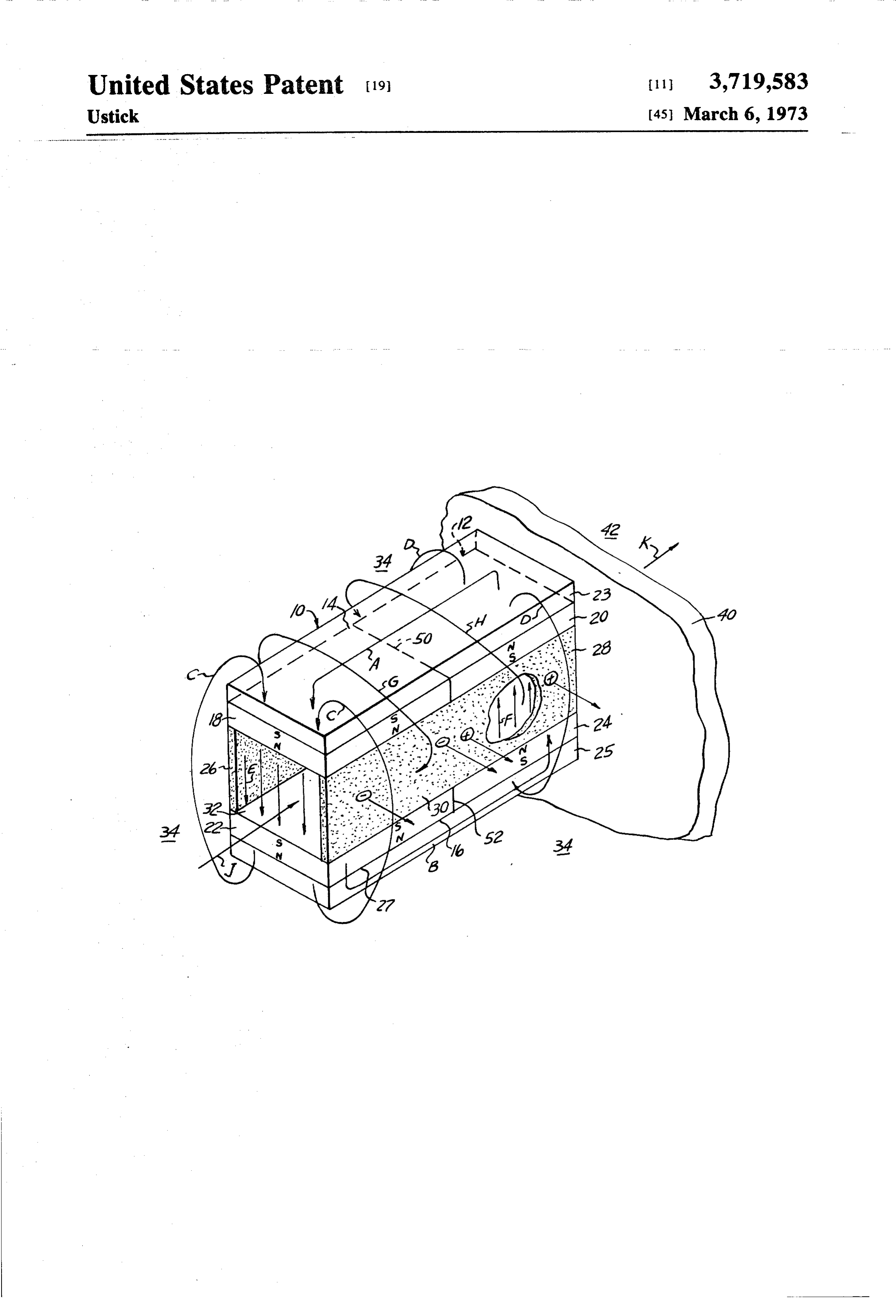
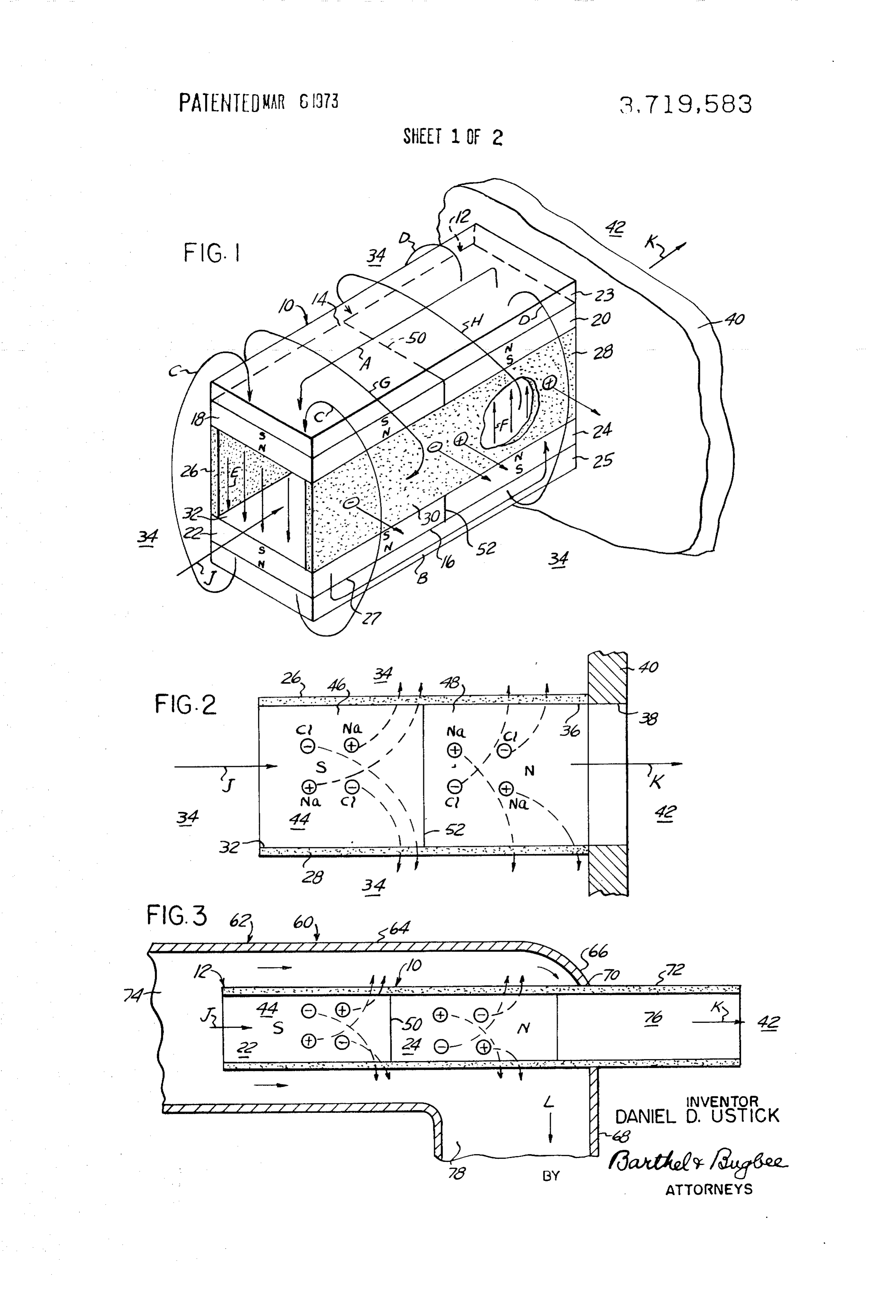
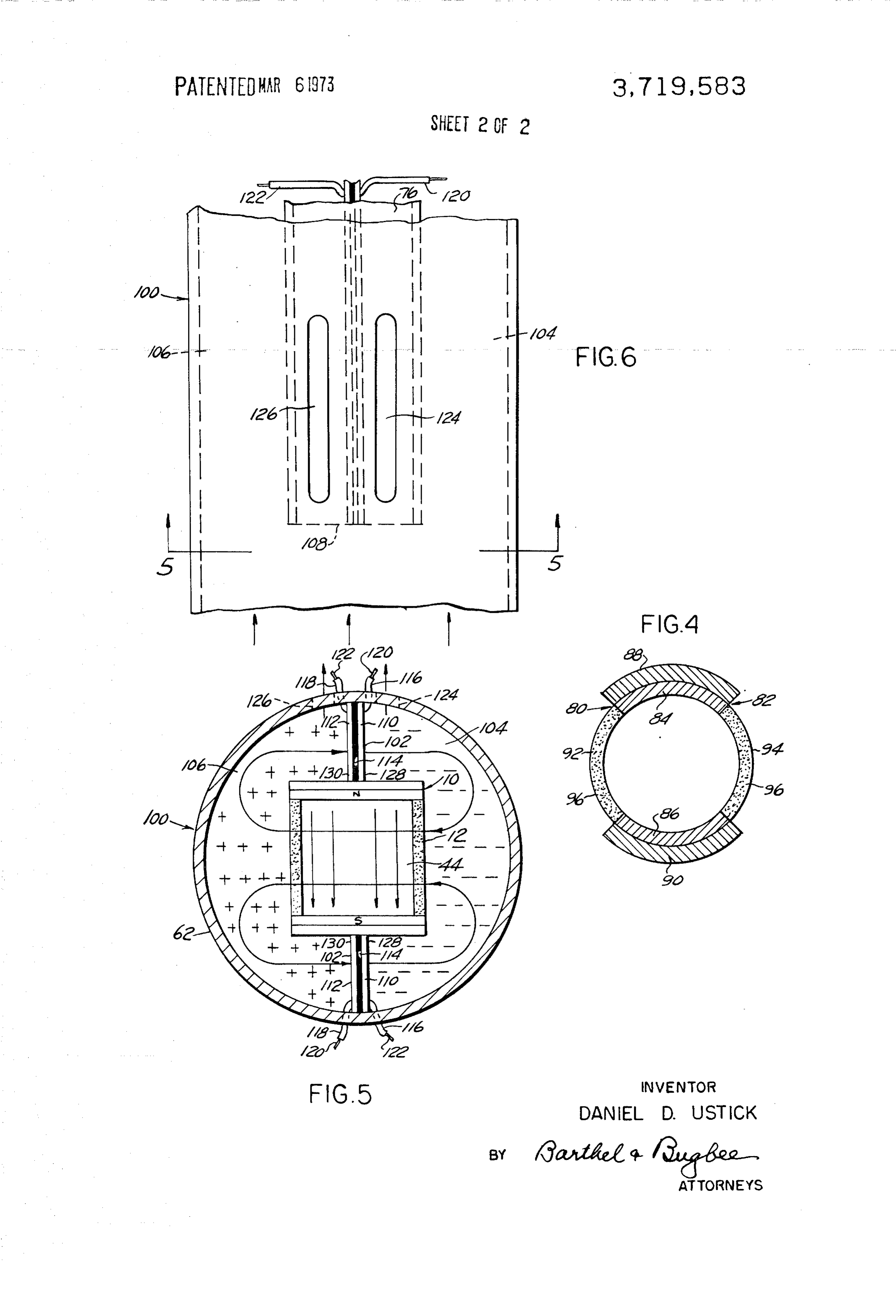
In the drawings, their upper and lower surfaces, and a similar relation FIG. 1 is a perspective view of a portion of an ap ship exists between the upstream and downstream mag paratus for the separation of ions from a solution such nets 22 and 24 on the lower side of the conduit 12 also as an electrolyte, according to one form of the inven for the purpose of reducing the outward spread of the tion, employing permanent magnets, and wherein the external magnetic field. The flux of the external mag solution flows into the conduit directly from a body O netic field is indicated by the arrows designated A and thereof, such as saltwater; B for the longitudinal external magnetic lines of force FIG. 2 is a central horizontal section through the ap and C and D for the transverse external magnetic lines paratus shown in FIG. 1 diagrammatically indicating of force. The lines of force of the internal magnetic the direction of ion travel; field between the upstream opposite magnets 18 and 22 FIG. 3 is a central horizontal section through a 15 are indicated by the reference letter E, whereas those modified ion separation apparatus wherein the solution between the downstream opposite magnets 24 and 20 flow is through an outer conduit surrounding the inner are indicated by the reference letter F, the flow of the conduit containing the solution under ion separation; magnetic flux being of course in opposite directions FIG. 4 is a cross-section through a further modifica because of the opposite arrangement of the magnetic tion wherein the inner conduit is of circular rather than poles. The corresponding electric field is indicated by rectangular cross-section and the electromagnets and the arrow G for the upstream magnets 18 and 22 and by the field-restricting plates are of arcuate cross-section; the arrow H for the downstream magnets 20 and 24. FIG. 5 is a cross-section through a still further From the location of the arrow heads of the arrows G modification of FIG. 3, wherein the space between the and H it will be seen that the electric field is disposed in outer and inner conduits is partitioned by a diametral 25 opposite directions, just as the opposite locations of the barrier composed of electrically-conducting walls arrows heads C and D as well as E and F show opposite separated by an insulating layer and adapted to deliver directions of the magnetic flux.
current electricity to an external circuit; and In the operation of the ion separation apparatus 10 of FIG. 6 is a top plan view of a length of the still further FIGS. 1 and 2, let it be assumed that it is to be used for modified device of FIG.S. 30 the desalinization of salt water, such as sea water, Referring to the drawings in detail, FIGS. 1 and 2 which occupies the space 34 to the left of the bulkhead show an ion separation or desalinization apparatus, 40 generally designated 10, consisting of a conduit 12 of fromandthethat the space to the right thereof is sealed off rectangular cross-section having upper and lower walls place therebetweenspace saltwater 34 so that no water flow takes except through the passageway 44 14 and 16 respectively containing upstream and 35 extending through the conduit 12. Let it also be as downstream permanent magnets 18 and 20 on the sumed that incoming salt water is caused to flow in the upper side and upstream and downstream permanent direction of the arrow J through the inlet opening 32 magnets 22 and 24 on the lower side thereof.
Disposed externally of and adjacent the magnets 22 and through the conduit passageway 44 and thence, and 24 are field-restricting plates 23 and 25 of fer 40 after desalinization through the outlet openings 36 and romagnetic material which provide easy flux for the 38 into the desalinized water space 42. Consider, for magnetic lines of force and confine the external mag example, the behavior of the sodium chloride ions in netic field substantially therein and minimize its out the salt water. As the salt water flows through the passageway 44, the positive sodium ions and the nega ward expansion which would reduce the efficiency of tive chloride ions into which the sodium chloride dis the apparatus 10. The magnets 18, 20, 22 and 24 and the plates 23 and 25 are preferably of ceramic mag sociates in water solution are subject to the action of netic material, such as ceramic barium ferrite. Such the electromagnetic field, in accordance with the laws ceramic materials are electrically non-conducting of magnetohydrodynamics, as indicated by the arrows hence are not as readily attacked by the solutions lettered E and F for the magnetic field provided by the because they will not transmit the currents generated 50 magnets 14 and 16 and G and H for the electric current by the ions moving in the magnetic field. They also pos resulting from the flow of ions through that magnetic sess a high coercivity, producing very stable magnetic field, whereby the positive sodium ions and negative fields. chloride ions are deflected laterally in opposite The two remaining opposite side walls 26 and 28 are directions. At the same time, the flow of water through of porous material, such as porous ceramic material, 55 the conduit 12 is retarded by the effect of the magnetic for example unglazed porcelain, having minute pores flux in performing the ion separation and deflection. As indicated diagrammatically at 30 through which the a consequence, the positive sodium ions in the space 46 ions of dissociated salt water can readily pass. These between the magnets 18 and 22 are expelled through ions are indicated by tiny circles bearing positive and the pores of the side wall 26, whereas the negative negative signs. The conduit 12 has an inlet opening 32 60 chloride ions therein are expelled through the pores of from a salt water space 34 indicated at the left-hand the opposite side wall 28 back into the salt water space side of FIG. 1 and an outlet opening 36 communicating 34.
with an outlet opening 38 in an impermeable bulkhead From the space 46 between the magnets 18 and 22, or partition wall 40 to which the conduit 12 is attached 65 the partly desalinized water containing the remaining and which excludes the salt water from the desalinized sodium and chloride ions passes into the space 48 water space 43 downstream from the outlet opening between the oppositely arranged magnets 20 and 24 38. past the boundary surfaces 50 and 52 respectively
Page 6
between the two sets of opposed magnets. The electric cross-section rather than of rectangular or straight field now acts in the opposite direction as indicated by cross-section. In particular, the conduit 82 is of annular the arrow H (FIG. 1), causing the positive sodium ions cross-section having upper and lower walls 84 and 86 to be expelled through the porous side wall 28 while the containing upstream and downstream permanent mag negative chloride ions are now expelled through the nets 88 and 90 respectively. It will be understood that, pores in the porous side wall 26. As a result, the water as shown in FIG. , the permanent magnets 88 on the flowing outward in the direction of the arrow K pos upper side and the magnets 90 on the lower side al sesses a reduced salinity to the extent that it is ternate in polarity the same as the upper side magnets designated fresh water. The amount of desalinization 10 18 and 20 and the lower side magnets 22 and 24 in FIG. for a satisfactory result will of course depend on the 1. As in FIGS. 1 and 2, the two remaining side walls 92 subsequent use for which the water is intended. Water and 94 are of porous material, such as porous ceramic for bathing, drinking and laundry purposes may possess material like unglazed porcelain having minute pores a much higher salinity than boiler feed water, which indicated diagrammatically at 96 through which the must possess negligible salinity in order to avoid corro 15 ions of electrolytes such as the sodium and chlorine sion of the boiler tubes. It will be understood that the ions of sodium chloride solution can readily pass. The apparatus 10 shown in FIG. 1 may be arranged in operation of the ion separation apparatus 80 of the cascade so as to subject water of already lowered salini FIG. 4 modification is substantially the same as that of ty to further desalinization steps and thus meet varying FIGS. 1, 2 and 3 and hence requires no additional requirements of minimum salinity for the fresh water description.
finally obtained in the space 42. The still further modified ion separation apparatus, The modified desalinization apparatus, generally generally designated 100, shown in FIGS. 5 and 6 is designated 60, shown in FIG. 3 is generally similar to generally similar in construction to that shown in FIGS. the apparatus 10 shown in FIGS. i and 2 except that 1, 2 and 3 and similar numerals are employed to the ionized solution to be deionized is supplied through 25 designate similar parts. In the still further modified ap an external supply conduit 62 surrounding the ap paratus 00, however, a diametral composite partition paratus 10 in spaced relationship thereto rather than 102 has been set up between the opposite sides of the having the apparatus 10 immersed in an open body of external supply conduit 62 of FIG. 3 in order to provide the ionized solution, for example, salt water such as in a liquid-impenetrable barrier therebetween and pro the open sea, as in FIGS. and 2. Accordingly, the 30 vide two completely separated fluid passageways 104 same principles apply and the desalinization apparatus and 106 on opposite sides thereof. Interflow between 60 within the supply conduit 62 bears the same the opposite sides can of course take place upstream reference numerals as in FIG. 1 for the corresponding from the upstream end 108 of the ion separation ap elements. paratus 10 constituting the inner portion of the ap In the apparatus 60, however, the longitudinal por 35 paratus 100, but such interflow is effectively prevented tion 64 of the conduit 62 is provided with a bend 66 downstream beyond the end 108 by the composite bar leading to a transverse portion 68 with an opening 70 rier 102 and continues throughout the length of the ion therein corresponding to the opening 38 in the bulk separation apparatus 10 beyond the upstream end 108 head 40. Beyond the opening 70, the conduit 12 is con 40 thereof.
nected to a fresh water discharge conduit 72 leading to The composite partition 02 above and below the a place of disposal of the fresh water obtained. The ar ion separation apparatus 10 inside the conduit 62 con rangement of magnets in the modified apparatus 60 is sists of walls 10 and 112 of electrically conducting the same as that in the apparatus () and the operation material spaced laterally apart from one another and is also substantially the same. The ionized solution as 45 separated in that space by a layer or wall 114 of electri before flows in the direction of the arrow J from the cally insulating material. Since electric current is inlet passageway 74 within the supply conduit 62 and generated in the operation of the apparatus 100, as will thence into the passageway 44 within the conduit 12 appear from the description thereof below, insulated and, after desalinization, outward through the conductors 116 and 118 respectively are connected to passageway 76, with the direction of flow again in 50 the walls 110 and 112 on opposite sides of the insula dicated by the reference letter K. The non-de-ionized tion layer 114 and their conducting cores 120 and 122 water flowing beyond and outside the conduit 12 respectively may be connected to an external circuit to escapes through the passageway 78 in the bent section operate various electrical devices which are actuated 58 of the conduit 62, in the direction indicated by the by electric current. Added to the outer conduit 62 of arrow L. 55 FIG.3 on opposite sides of the composite partition 102 It will be understood that the flow of ionized solution are elongated gas discharge ports 124 and 126 respec through the conduit 12 in any form of the invention as tively (FIG. 6) through which the gases generated dur shown in FIGS. 1 and 2, in FIG. 3, in FIG. 4, and in ing the operation of the apparatus 10 may escape. It FIGS. 5 and 6 is preferably enhanced by the provision 60 will be evident to those skilled in this art that gas-con of suitable pumping means. Such pumping means is ducting conduits may be coupled to the gas discharge especially desirable in the modified apparatus shown in ports 124 and 126 whereby the gases produced during FIGS. 3, 5 and 6. the operation of the ion separation apparatus 100 may The further modified ion separation apparatus, be carried away to a place of utilization or storage. generally designated 80, shown in FIG. 4 is the same in The operation of the still further modified ion principle as the ion separation apparatus 10 in FIGS. 1, 65 separation apparatus 100 is substantially the same as 2 and 3 and differs from these forms of the invention that described above in connection with FIGS. 1, 2 and only in that its components are of circular or arcuate 3 and hence requires no repetition except for the addi
Page 7
tional actions resulting therefrom. The electrical con a conduit having an internal passageway therein with ducting walls 10 and 112, preferably of metal, and an inlet adapted to be connected to a source of separated by the insulating layer 14, act as anode and ionized solution arranged to flow through said cathode respectively providing an electrical potential passageway and having an outlet remote from said difference of voltage when an electrolyte is pumped 5 inlet, through the inlet passageway 74 and thence through means disposed on two opposite sides of said conduit the passageway 44 within the inner conduit 12 and, for setting up a magnetic field extending across after desalinization or ion separation, outward through said passageway in a direction transverse to the the passageway 76. The non-de-ionized water flowing direction of flow of said ionized solution through beyond and outside the conduit 12, however, instead of 10 said passageway, escaping through the passageway 78 of FIG. 3 now opposite walls extending between said opposite sides escapes through the divided and separate passageways of said conduit having means associated therewith 104 and 106. In addition, when the cores 120 and 122 for the remgoval of the ions expelled across said of the insulated conductors 116 and 118 are short-cir passageway in response to the action of said mag cuited by being connected into an external electrical 15 netic field, - -- -
second conduit disposed externally of said first
circuit to operate electrical devices constituting an mentioned conduit in laterally spaced relationship electric load, the walls 110 and 112 provide surfaces thereto providing an external passageway 128 and 130 upon which gases and certain solids or therealong, solid compounds may either precipitate out of solution said second conduit being adapted to be con or remain in solution, as the case may be. 20
The still further modified ion separation apparatus nected to the source of ionized solution, said inlet of said first-mentioned conduit commu 100 and the method practised by its use differs from the nicating with said external passageway of said method of electrolysis in the types of energy transfor second conduit, mation taking place therein. In the still further and means for pumping said ionized solution from modified ion separation apparatus 100 of FIGS. 5 and 25 said source through said internal and external 6, mechanical energy provided by the liquid pump (not passageways, shown) or other suitable source providing electrolytic said opposite walls of said first-mentioned conduit flow performs work in separating the ions from the being of porous construction with pores capable electrolyte passing through the inlet passageway 74 and of transmitting therethrough the ions expelled thence through the ion separation passageway 44 into from said passageway. the outlet passageway 76 and converts these ions into gases, solids or various compounds, accompanied by wherein ion 2. An separation apparatus, according to claim 1, said conduit is of approximately rectangular the generation of electricity. In brief, in my apparatus cross-section with two pairs of substantially parallel op 100, mechanical energy is converted into electrical posite walls, wherein said magnets are disposed ad energy and chemical potential energy. 35
In electrolysis, on the other hand, electrical energy is jacent one pair of said opposite walls, and wherein the fed into electrolytic apparatus for the purpose of per means for removing the expelled ions includes the forming work on the ions in solution and thereby con porosity of the other pair of said opposite walls. 3. An ion separation apparatus, according to claim 1, verting them into gases, solids or various compounds, wherein a composite liquid-tight partition made up of thereby converting electrical energy into chemical 40 two electrically conducting walls separated from one potential energy. another by an electrically insulating layer is disposed From the foregoing description, it will be evident to between said first and second conduits and separates those skilled in the art that the present apparatus and the intervening space therebetween into a plurality of method, while described particularly with reference to separated liquid passageways, and wherein means is the elimination from sea water of common salt (sodium 45 provided attached to said walls for connecting said chloride), is equally applicable to the elimination of the walls to an external electric circuit. lesser salts present in sea water, and also for the separa 4. An ion separation apparatus, according to claim 3, tion of the ions from other ionized solutions, since the wherein gas outlet ports are provided in said first con same scientific principles apply thereto.
I claim: 50 duit for outward flow therethrough of gases released 1. An apparatus for the separation of ions from an during the operation of said apparatus.
ionized solution, comprising
Provenance
- Collection
- Cited prior art
- Original PDF
- patentimages.storage.googleapis.com →
- Filed
- 1970-07-06
- Pages
- 7
- Method
- pdftotext (the PDF's own text layer) + pdftoppm 300dpi page scans
- Source
- Google Patents bibliographic record
- Granted
- 1973-03-06
- Inventors
- D Ustick
- Transcribed from
- patentimages.storage.googleapis.com →