patent · US3214362
Electrolysis of aqueous electrolyte solutions and apparatus therefor
26 October 1965
Page 1
Drawing sheet — no readable text.
Page 2
Drawing sheet — no readable text.
Page 3
United States Patent Office 3,214,362 Patented Oct. 26, 1965
prises a novel bipolar electrode. Other objects of the 3,214,362 invention will in part be obvious and will in part appear
ELECTROLYSIS OF AQUEOUS ELECTROLYTE hereinafter. The invention accordingly comprises the SOLUTIONS AND APPARATUS THEREFOR process involving several steps and the relation and order Walter Juda, Lexington, Mass, assignor to Ionics of one or more of such steps with respect to each of the Incorporated, Cambridge, Mass, a corporation of
Massachusetts others, and apparatus possessing the construction, com Filed Jan. 9, 1961, Ser. No. 81,334 bination of elements and arrangement of parts which are 10 Claims. (C. 204-255) exemplified in the following detailed disclosure, and the Scope of the application of which will be indicated in
This invention relates to electrolysis of aqueous elec O the claims.
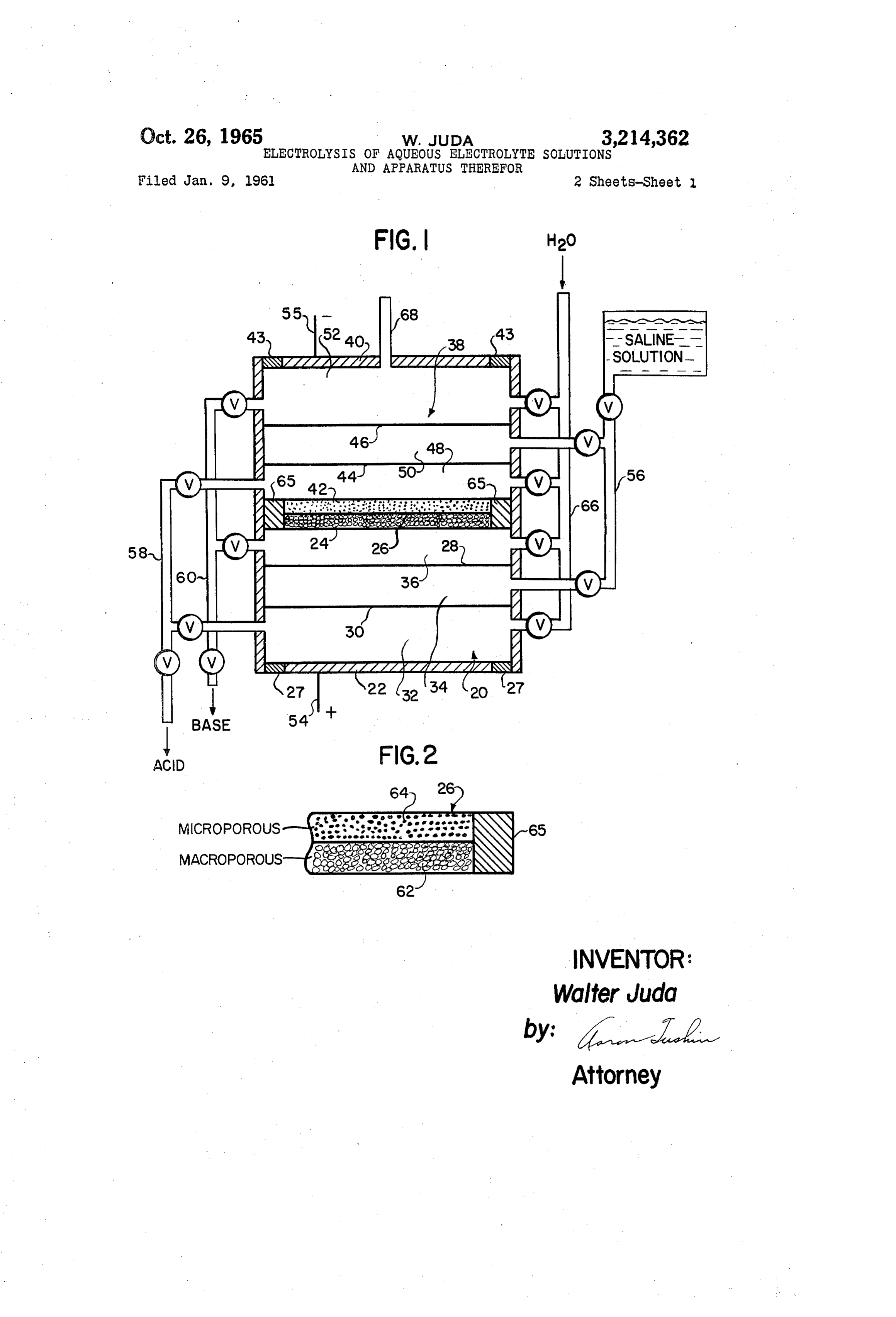
trolyte solutions, and more particularly to the electrolytic For a fuller understanding of the nature and object conversion of a concentrated salt solution to an acid and of the invention, reference should be had to the follow a base, and novel apparatus for performing the conver ing detailed description taken in connection with the ac S10. companying drawing in which:
It is known that the passage of a direct electrical cur 15 FIGURE is a schematic, side elevational, cross-sec rent of Sufficient magnitude through an aqueous salt tion diagram of a plurality of cells forming an embodi Solution between a cathode and an anode immersed there ment of an apparatus of the invention; in results in the electrolytic separation of the salt to form FIGURE 2 is an enlarged diagrammatic cross-sectional a base in the catholyte and an acid in the anolyte when view of a bipolar electrode element of the embodiment of the anode and cathode are maintained in separated com 20 FIGURE 1;
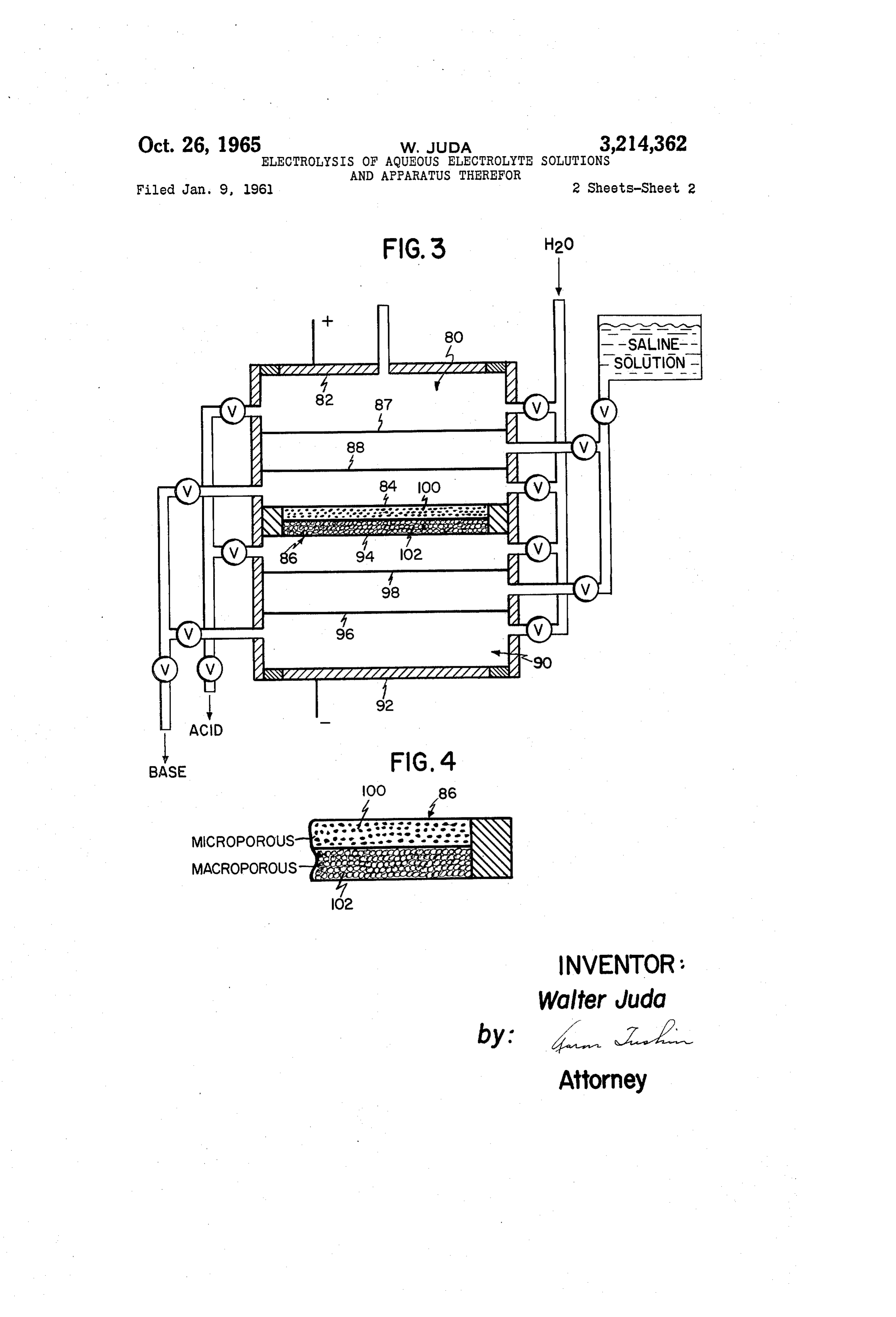
partments. Where the salt, for instance, is an alkali FIGURE 3 is a schematic, side elevational, cross-sec metal Salt, alkali metal hydroxide and an acid are pro tional view of a plurality of cells forming another embodi duced, but the anode is subject to chemical attack by ment of an apparatus of the invention; and oxygen produced therein as a reaction product. This FIGURE 4 is an enlarged cross-sectional view of a not only necessitates frequent replacement of the anode, 25 bipolar electrode of the embodiment of FIGURE 3. but results in low current efficiencies in the operation of For the purposes of illustration, application of the in the process. vention to the electrolytic conversion of aqueous sodium Fuel cells, known in the art, can be characterized as Sulfate is detailed herein. The conversion of sodium sul electrochemical devices in which a substantial portion of fate to sulfuric acid and caustic soda has recognized com the chemical energy of an oxidation-reduction reaction mercial significance. In the well-known viscose process, is converted directly to useful electrical energy. A typical for instance, the digestion of cellulose in caustic soda fuel cell comprises a pair of porous, catalyzed electrodes forms the sodium salt of the former which is then reacted Separated by an electrolyte, means for introducing a fuel, with carbon disulfide to yield a viscous, colloidal, Xanthate Such as hydrogen into one of the electrodes, and means sol in dilute aqueous alkali. After the Xanthate has been for introducing an oxidant gas, such as air, into the other allowed to ripen, the cellulose is regenerated in filament of the electrodes. The reaction of the fuel and oxidant form by precipitation in a solution comprising sulfuric creates electrical energy which is then available at the acid, thereby forming sodium sulfate. Thus, caustic soda electrodes. and sulfuric acid are employed in large quantities in the The use of electrolytic cells for effecting electrochemical viscose industry and the conversion of the “waste' sodi conversions with electrical energy derived, at least in part, 40 um sulfate back to the original acid and base at a reason from the use of one or more porous, catalyzed electrodes able cost is a highly desirable object. Many efforts have to which are fed a fuel or oxidant in accordance with been directed toward converting the sodium sulfate for the requirements of the process and the nature of the par reuse in the viscose process and some examples of meth ticular catalytic electrode, has been disclosed in co 45 ods heretofore proposed may be found in the patent pending U.S. patent applications, Ser. No. 842,892, filed literature for example, U.S. Patent No. 2,273,795, and September 28, 1959, now U.S. Patent No. 3,124,520; Ser. British Patent No. 764,181. In the electrochemical meth No. 3,259, filed January 19, 1960, now U.S. Patent No. ods heretofore proposed, the costs of the electrolytic con 3,028,417; and Ser. No. 7,046, filed February 5, 1960, now version of sodium sulfate has been largely determined by
anode process, i.e., the ionization of a fuel supplied to 50 In most electrolytic cells for the electrolysis of concen the anode, was employed to produce, by direct conver trated solutions of alkali salts, such as sodium sulfate, the sion, part of the energy consumed in the overall process. individual cells each comprise a plurality of compart In co-pending U.S. patent applications, Ser. No. 8,269, ments defined by one or more permeable partitions or filed February 12, 1960 now abandoned, and Ser. No. barriers disposed in the inter-electrode space. Such parti 66,498, filed November 1, 1960, now U.S. Patent No. 55 tions have been in some instances simple porous dia 3,125,017, part of the direct current used for the electro phragms such as in the cell disclosed in U.S. Patent No. chemical conversion of certain compounds was produced 1,126,627, or they have been formed as ion permselective by the cathode process, i.e., the ionization of an oxidant membranes, such as in the cell disclosed in U.S. Patent supplied to the cathode. No. 2,723,229. Such barriers or permeable partitions Consequently, a principal object of the present inven 60 have been included primarily to minimize intermixing tion is to provide a novel process for the electrolysis of of the products formed at the electrodes while providing saline electrolyte solutions to form basic and acidic aque a comparatively free path for the passage of electrical ous products with a considerable saving in the electrical current from one electrode to the other. energy required. Other objects of the present invention One embodiment of the invention generally comprises are to provide a novel apparatus for performing the 65 a multicellular apparatus such as a plurality of electrolytic process of the invention; to provide an apparatus for cells in linear adjacent array, the interior of each cell be performing said process which is compact, produces the ing separated from the interior of the next adjacent cell base and acid at a substantially reduced cost, is simple by a unitary, bipolar electrode. Each bipolar electrode to operate, and in which the problems of corrosion by 70 is formed as a unitary element comprising an anodic sur and disposal of gaseous by-products is Substantially face and a cathodic surface. One end cell of the array lessened; and to provide such an apparatus which com includes a cathode while the other end cell includes an
Page 4
anode. Thus, each cell comprises a pair of electrodes, apart relation to one another, the interspace between them and the array is arranged with the anode and anodic Sur also being divided by a pair of permeable barriers 44 and faces and the cathode and cathodic surfaces alternate in 46 into an anode chamber 48, intermediate chamber 50 sequence so that when the cells are filled with an aqueous and cathode chamber 52. Barriers 44 and 46 are substan electrolyte, the passage of current between the anode and 5 tially of the same type as barriers 28 and 30, depending cathode evolves hydrogen gas at the cathode and at the of course upon the particular embodiment of the inven cathodic surfaces of the bipolar electrodes. The anode tion desired. It will be seen that the barriers within each surfaces are formed as electrically conductive, micro cell are so disposed that the communication between the porous, catalyzed elements, and the cathodic Surfaces chambers formed by the barriers may be had only through comprise electrically conductive, porous means for in O the latter.
troducing hydrogen gas formed thereat into an associated Anode 22 and cathode 40 are respectively connected anodic surface. The gas diffuses from the cathodic Sur to means, such as electrically conductive leads 54 and 55, face into the anodic surface where it is dissociated into for impressing a D.C. potential across the apparatus. ions by the catalytic action of the latter. Catalysts which Means are provided for introducing an aqueous solution are effective for the purpose involved herein are well 5 of a Salt into the intermediate chambers of each cell, and known, per se, and may for example be found in the in the form shown, this comprises a conduit or manifold patent to Grubb No. 2,913,511, column 3, lines 40 et seq. 56 ported to the intermediate chamber of each cell so as The ions are displaced from the surface of the catalyst to provide a common feed thereto. Means are also pro so as to be driven through the tri-phase boundary formed vided for removing aqueous effluent from each anode by electrolyte, leaving a current producing electron at 20 chamber of each cell, and in the form shown, the latter the anode for each ion formed. Each cell preferably in means comprises a conduit or manifold 58 joining all of cludes one or more ion-permeable barriers disposed be the anode chambers in common. Similarly, means such tween the cell electrodes. as manifold 60 are provided for removing aqueous effluent Referring now to the drawings, there is shown in FIG from each of the cathode chambers of each cell, manifold URE 1 an embodiment of an apparatus for performing 25 60 being connected to the cathode chambers to form a the process of the invention and comprising a plurality of common conduit therefrom.
three-compartment cells. In the form shown, the appa The individual cells forming the invention may be ratus is shown as a two-cell structure comprising a first Varied as to size of the cell, as to both the size and num substantially hollow cell 20 including a positive electrode ber of the individual chambers or compartments in each or anode 22 and a negative electrode which, in the form 30 cell, the form of the means for supplying aqueous salt shown, is cathodic surface 24 of bipolar electrode 26 de Solution to the center or intermediate chambers, the scribed in more detail hereinafter, the anode and cathode means for removing the aqueous effluent from the anode Surface being in spaced-apart relation to one another. and cathode chambers, valving, and the material from Anode 22 is preferably electrically insulated by known Which the cell bodies or enclosures are formed. How means, such as insulator 27, from the body of the cell. 35 ever, adjacent cells must be separated from one another The interspace between anode 22 and cathodic surface 24 Substantially only by a bipolar electrode common to the is divided by a pair of permeable barriers 28 and 30 into two cells. In the preferred form, all of the bipolar elec anode chamber 32, intermediate chamber 34 and cathode trodes (a portion of such an electrode being shown in en chamber 36. Barriers 28 and 30, in one form of the larged cross-section in FIGURE 2) comprise a cathode invention, comprise macroporous, fluid-permeable dia 40 portion 62 and an anode portion 64 of equal size. Where phragms, formed for instance of porous ceramic plates, the electrode is intended to catalyze a fuel gas, such as fiber asbestos cloth or matting, or other materials well hydrogen, the porosity, and therefore the specific surface known in the art and substantially inert with respect to area of the bipolar electrode, is graded from the cathode the fluids intended to permeate therethrough. portion to the anode portion, the two portions being pneu
In an alternative embodiment, the barriers comprise matically connected to one another. In the preferred ion-permselective membranes generally formed of a solid, embodiment of a hydrogen catalyzing electrode, cathode sheet-like, polymeric structure preferably reinforced by portion 62 is preferably substantially macroporous, while an enbedded Screen, mat, or the like, and containing ion the anode portion 64 preferably is a substantially micro eXchange resins fixed in the polymeric matrix. One of porous, catalyzed element having a very high surface the cell membranes, for instance barrier 28, is a film or 50 area. This may be accomplished, for example, by form layer containing a cation-exchange resin, well known in ing the anode portion of a sintered mat of catalytic, metal the art and examples of which are described in U.S. Patent micro-filaments, such as nickel powder activated by plati Nos. 2,731,408, 2,731,411, etc. A preferred form of cat nun, or a Sponge of platinum, iridium, palladium, rho ion permselective membranes is one which contains car dium, and other metals chosen from Group VIII of the boxylate groups such as a membrane manufactured by Periodic Table. Cathode portion 62 may be formed of copolymerizing divinyl benzene and an olefinic carboxylic nickel or steel Sponge, porous carbon, or the like. The compound such as an anhydride, ester, or acid chloride of cathode portion and anode portion are in intimate physi acrylic acid and its derivatives in solution in a suitable cal and electronic contact with one another throughout solvent. By saturating the polymerized solid material So as to form an integral unit by any convenient bonding with water, the anhydride, ester, or acid groupings in the 60 method known in the art which does not interfere with polymeric matrix is inverted to salt or acid forms of car either the pneumatic intercommunication between the por boxylate groups. The presence of an aqueous solvent tions or with the ready passage of electrical current from phase in the polymerized solid provides a structure which one portion to the other. Means, such as plastic seal 65, is both electrically conductive and selectively permeable formed of a substantially chemically inert, water and gas to cations. The other ion perm selective membrane, for 65 impervious material, for instance polytetrafluoroethylene, instance barrier 30, is then an anion perm selective mem polyvinyl chloride, and the like, is provided as a continu brane, well known in the art and examples of which are ous Strip around the common joined edges of the cathode described in U.S. Patent Nos. 2,730,768, 2,800,445, etc. portion and anode portion to insure that no gas leak can The structure of the apparatus also comprises a second occur at the edges of the bipolar electrode. Substantially hollow cell 38 including a negative electrode 70 In the form of the apparatus shown, there is included or cathode 46 and a positive electrode, which, in the form means, such as manifold 65 for providing a controlled shown, is anodic Surface 42 of bipolar electrodes 26. Supply of water to the anode and cathode chambers in Cathode 40 is preferably electrically insulated from the order to control the concentration of the products formed body of the cell by means, such as insulator 43, known in in the latter and to assist in governing the flow of fluid the art. Cathode 40 and anodic surface 42 are in spaced through the apparatus.
Page 5
In keeping with the discussion of the electrolytic con jacent the anode, another adjacent the cathode, and a Version of aqueous sodium sulfate set forth hereinbefore, third chamber intermediate the first two. The structure the operation of the invention will be described with rela also comprises a second cell 90 including a cathode 92 tion to that process. In operation, a solution of sodium and a positive electrode comprising anodic sulface 94 of sulfate is fed through manifold 56 to intermediate cham 5 the bipolar electrode, the latter forming an element which bers 34 and 50 of each cell. Where barriers 28, 30, 44, Separates the cells one from the other. The interspace and 46 are porous diaphragms, it is desirable to main between the electrodes of cell 90 are also divided by tain a steady flow of electrolyte into the cells through a pair of permeable barriers 96 and 98 into three cham manifold 56 in order to prevent back-migration of the bers. It should be noted that the apparatus, as is the ions. Simultaneously, a stream of water is fed into each O apparatus of FIGURE 1, is preferably constructed so anode chamber and cathode chamber through manifold that the cells are stacked in a vertical array, but in this 66. When a D.C. electric potential is initially applied embodiment the anode chamber of each cell is at the top to the apparatus at anode 22 and cathode 40, the resist most portion thereof while the cathode chamber of each ance is first comparatively high until the ion concentra cell is at the bottom.
tion in the cathode and anode chambers becomes sufi Bipolar electrode 86, which separates the two cells, cient to readily conduct the electric current therethrough. and a portion of which is shown in enlarged cross-section This occurs in a comparatively short time interval. The in FIGURE 4, comprises a cathode portion 100 and an Sodium ions and Sulfate ions, under the influence of the anode portion 102 of substantially equal size. Because applied electrical potential, move from the center cham the bipolar electrode in this embodiment is intended to bers to the respective adjoining cathode and anode cham 20 catalyze an oxidant gas, such as oxygen, the porosity and bers, caustic soda being formed in the cathode chambers therefore the specific surface area of the electrode is and Sodium acid Sulfate being formed in the anode cham graded from the anode portion to the cathode portion, bers. Along with the production of the acid and base, the two portions being pneumatically connected and in hydrogen gas is formed at the respective cathodes while intimate physical and electronic contact with one an OXygen is produced at the anodes. 25 other. In the preferred embodiment of an oxygen cata It should be noted that the apparatus of FIGURE 1 is lyzing bipolar electrode, anode portion 02 is prefer preferably constructed so that the cells are stacked in a ably a substantially macroporous body, while cathode vertical array with the cathode compartment of each cell portion 100 preferably is a substantially microporous, at the top and the anode compartment of each cell at catalyzed element having a very high Surface area. the bottom. Thus, the hydrogen produced at the cath 30 Cathode portion 100 is formed, for example, of micro Ode of the lower-most cell of the array tends to rise and, porous carbon catalyzed with silver, gold or other noble diffusing readily through the porous structure of the cath metals, or as a microporous silver element. Anode por ode, permeates the anodic portion of the bipolar elec tion 102 in turn is formed, for instance, of steel sponge trode separating the lower cell from the next upper-most or macroporous carbon or the like. In all other respects, cell. The hydrogen gas thus diffused into the anodic 35 bipolar electrode 86 is formed similarly to the bipolar portion of the bipolar electrode is dissociated into ions electrode heretofore discussed in connection with FIG by the catalyst contained in the anodic portion of the URE 2 bipolar electrode. The ions thus formed are displaced In operation, the electrolysis of a saline solution in from the surface of the catalyst and are injected into the troduced into the said compartments through appropriate anode chamber wherein they combine with oxygen pro 40 conduit means is quite similar to the operation of the duced at the anode to form water, thus preventing anode apparatus of FIGURE 1 heretofore described. The ions attack by the oxygen. For each such ion displaced from of the dissociated salt, under the influence of applied the anodic portion, a current producing electron is re electrical potential, move from the intermediate cham leased, thereby providing a portion of the electrical power bers through the adjoining ion-permeable barriers to the required for the process. The construction of the bipolar respective adjoining cathode chamber and anode cham electrode therefore provides an apparatus where hydro ber, a base being formed in the former and an acid be gen produced at the cathodic portion of each bipolar ing formed in the latter. Simultaneously, oxygen gas is electrode is employed to contribute to the over-all elec produced at the respective anodes while hydrogen gas is trical power required in the process and substantially re formed at the respective cathodes. Because of the ver duces the effective internal resistance of the apparatus. tical construction of the cell, the OXygen produced at the Of course, because the cathode of the upper-most cell is anode of the lower-most cell tends to rise and diffuse not necessarily porous nor does it necessarily form a por readily through the porous structure of the anodic por tion of a bipolar electrode, the hydrogen produced thereat tion permeating into the cathodic portion of the bipolar does not diffuse into an adjacent cell. Instead, means, electrodes separating the lower cell from the next adja such as outlet port 68 are provided for venting the hy 5 5 cent cell. The oxygen gas thus fed into the cathodic drogen gas which may then be lead to a microporous, portion of the bipolar electrode is dissociated into ions catalyzed form of anode 22 through appropriate duct by the catalyst contained in the latter and the ions are work or conduit means, or may be disposed of in some injected into the cathode chamber wherein they combine other manner. From the respective cathode compart with the hydrogen produced at the cathode to form wa ments, a high purity grade of sodium hydroxide solution 60 ter. For each such ion displaced from the cathodic por is continuously withdrawn through manifold 60 while tion, a current producing electron is released, thereby from the respective anode compartments a mixture of providing a portion of the electrical power in a manner sodium sulfate and Sulfuric acid, i.e. sodium acid sui similar to that heretofore described. fate, is withdrawn through manifold 58. The apparatus herein disclosed for performing the proc In another embodiment of an apparatus for perform ess of the invention is useful for many processes. For ing the process of the invention, shown particularly in instance, the apparatus of FIGURE 1 is useful for per FIGURE 3, the apparatus again comprises a two-cell forming a dual process at the cost of electrical power structure comprising a first cell 80 including an anode ordinarily required for but one of the processes. Refer 82 and a negative electrode comprising cathodic Surface ring to FIGURE 1, a similar apparatus thereto is used 84 of bipolar electrode 36 described hereinafter. The 70 wherein permeable barriers 28, 30, 44 and 46 are re anode and cathode surfaces are in spaced-apart relation moved. Into cell 38 there is introduced a solution of to one another and, analogously to the embodiment of CuSO4, this cell being provided with a cathode 40 upon FIGURE 1, the interspace between the electrodes is di which Cu is intended to plate out and therefore can be vided by a pair of permeable barriers 87 and 88 of the formed of many electrically conductive materials such as type hereinbefore described into three chambers, one ad 75 Cu, Fe, Ni and the like. Cell 20 is provided with an
Page 6
7 S.
anode, such as graphite. Into cell 20 there is introduced electrode, and a chamber intermediate said anode and a solution of NaCl. Upon impressing a D.C. potential cathode chamber, said means for introducing a saline so across the two cells, Cu will plate out in cell 38 and lution being connected with each intermediate chamber of cell effluent will contain HSO4 contaminated with each cell, means for introducing water into each anode CuSO4 in varying degrees according to the cell voltage, and cathode chamber of each cell, means for removing the concentration and flow rate of the inflowing CuSO4. aqueous electrolytic products from each anode chamber, solution and the size of the cathode relative to the in and means for removing aqueous electrolytic products stantaneous concentration of CuSO4. Simultaneously, from each cathode chamber.
the NaCl solution is electrolyzed to produce NaOCl as 4. An aparatus as defined in claim 3 wherein said the effluent of cell 20. By inserting a porous diaphragm O permeable means comprise porous diaphragms. between the anode and cathodic surface in cell 20 and 5. An apparatus as defined in claim 3 wherein said flowing the NaCl into the interspace between the anode permeable means comprise ion-permselective membranes. and the diaphragm, the cell will produce NaOH with the 6. An apparatus for electrolyzing saline electrolyte so evolution of C1 at the anode. As with the embodiment lutions to form basic and acid aqueous products, said ap heretofore described in connection with FIGURE 1, the paratus comprising in combination, a plurality of Sub hydrogen evolved at cathodic surface 24 produces elec stantially hollow electrolytic cells in adjacent array, one trical power so that the voltage drop across the bipolar end cell of Said array including an anode, the other end electrode is negligible. Hence, it will be apparent that Sev cell of said array including a cathode, a plurality of bipolar eral useful products, HSO4 and either caustic soda, chlo electrodes for separating the interiors of adjacent cells, rine or NaOCl are produced with the electrowinning of 20 each of Said bipolar electrodes comprising a cathodic por copper with large savings of electrical energy. tion and an anodic portion in intimate physical and elec By replacing the CuSO4 solution with FeSO4 it will tronic contact with one another, one of the cathodic and be immediately apparent that the same structure can be anodic portions of each bipolar electrode bounding a por employed to produce both NaOCl (or NaOH and Cl) tion of the interior of a cell, the other of said cathodic and plate out iron instead of copper. In this latter proc 25 and anodic portions of each bipolar electrode bounding a ess, it is preferred to introduce a porous diaphragm or portion of the interior of a corresponding cell next adja cation exchange membrane to separate the cathode of cent to Said cell, the cathodic portions of each of said cell 38 from anodic surface 42 of the bipolar electrode bipolar electrodes being formed as electrically conductive, and flow the FeSO4 solution into the interspace between inacroporous bodies, the anodic portions of each bipolar the diaphragm and cathode. This maintains the solution 30 electrode being formed as electrically conductive, micro pH adjacent the cathode at a relatively high level and porous bodies including means for catalyzing hydrogen minimizes attack by the resulting acid upon the plated gas to form hydrogen ions, the cathodic and anodic por out metal. tions of each bipolar electrode being pneumatically con Since certain changes may be made in the above process nected to one another so that hydrogen formed at said and apparatus without departing from the scope of the Cathodic portions permeates the latter and diffuses into the invention herein involved, it is intended that all matter anodic portion connected thereto, means for introducing contained in the above description as shown in the accom a Saline electrolyte solution into each of said cells, and panying drawings shall be interpreted as illustrative and means for inapressing a D.C. potential across said array not in a limiting sense. 40 through said anode and said cathode.
What is claimed is: 7. An apparatus for electrolyzing saline electrolyte so 1. An apparatus for electrolyzing electrolyte solutions, lutions to form basic and acid aqueous products, said ap said apparatus comprising in combination, at least two paratus comprising in combination, a plurality of substan. electrolytic cells in adjacent array, one end cell of said tially hollow electrolytic cells in adjacent array, one end array including an anode, the other end cell of said array cell of Said array including an anode, the other end cell including a cathode, at least one bipolar electrode for of Said array including a cathode, a plurality of bipolar separating the interiors of adjacent cells, each of Said electrodes for separating the interiors of adjacent cells, bipolar electrodes comprising a cathodic portion and an €ach of said bipolar electrodes comprising a cathodic por anodic portion in intimate physical and electronic contact tion and an anodic portion in intimate physical and elec with one another, one of the cathodic and anodic portions tronic contact with one another, one of the cathodic and of each bipolar electrode bounding a portion of the in 50 anodic portions of each bipolar electrode bounding a por terior of a cell, the other of Said cathodic and anodic por tion of the interior of a cell, the other of said cathodic tions of each bipolar electrode bounding a portion of the and anodic portions of each bipolar electrode bounding interior of a corresponding cell next adjacent to said cell, a portion of the interior of a corresponding cell next ad one of the cathodic and anodic portions of all of said bipolar electrodes being formed as electrically conduc jacent to Said cell, the anodic portions of each of said bipolar electrodes being formed as electrically conductive, tive, microporous, catalyzed bodies, the other of said lmacroporous bodies, the cathodic portion of each bipolar cathodic and anodic portions of all of said bipolar elec electrode being formed as electrically conductive, micro trodes being formed as macroporous, electrically conduc porous bodies including means for catalyzing oxygen gas tive bodies, the cathodic and anodic portions of each to form oxygen ions, the cathodic and anodic portions of bipolar electrode being pneumatically connected to one 60 each bipolar electrode being pneumatically connected to another so that a gas formed at Said macroporous body One another So that oxygen formed at said cathodic por permeates the latter and diffuses into said microporous tions permeates the latter and diffuses into the anodic body wherein it is catalyzed, means for introducing an portions connected thereto, means for introducing a saline electrolyte solution into each of said cells, and means for electrolyte Solution into each of said cells, and means for impressing a D.C. potential across said array through said 65 impressing a D.C. potential across said array through said anode and said cathode. anode and said cathode.
2. An apparatus as defined in claim wherein said ar 8. In a multicellular electrolytic apparatus, a unitary, ray is vertical and said bipolar electrodes are so disposed electrically conductive, bipolar electrode including an that gas formed at said each macroporous body tends to anodic portion constituting the anode of one cell and a rise and diffuse through the latter and into the micro 70 Cathodic portion constituting the cathode of another cell, porous body in contact therewith. One of Said portions being formed as a porous body, the 3. An apparatus as defined in claim 2 including selec other of Said portions being formed as a microporous tively permeable means for separating each of said cells body, Said portions being in intimate electronic and physi into an anode chamber adjacent a positively biased elec cal contact with one another so that a gas formed by the trode, a cathode chamber adjacent a negatively biased electrolytic decomposition of water at said porous body
Page 7
diffuses into said microporous body, and a catalyst dis 1,738,372 12/29 Edgeworth-Johnstone --- 204-255 tributed within said microporous body for ionizing said 1,857,903 5/32 Wensley et al. --------- 204-280 gaS. 2,177,626 10/39 Muller --------------- 204-255 9. In a multicellular electrolytic apparatus, a bipolar 2,681,884 6/54 Butler ---------------- 204-98 electrode as defined in claim 8 wherein said anodic por 5 2,829,095 4/58. Oda et al. -------------- 204-98 tion is microporous, and said catalyst comprises a Sub 2,858,263. 10/58 Lucas et al. ----------- 204-256 stance capable of ionizing hydrogen gas to form hydrogen 2,947,797 8/60 Justi et al. ------------- 136-86 10IS. 2,955,999 10/60 Tirrell --------------- 204-290 10. In a multicellular electrolytic apparatus, a bipolar electrode as defined in claim 8 wherein said cathodic por O OTHER REFERENCES tion is microporous, and said catalyst comprises a sub Heise: “Transactions of the Electrochemical Society,' stance capable of ionizing oxygen gas to form oxygen ions. vol. 75, 1939, pp. 147-166. References Cited by the Examiner
UNITED STATES PATENTS
JOHN H. MACK, Primary Examiner.
1,303,519 5/19 Stuart ---------------- 204-256 15 JOHN R. SPECK, MURRAY TILLMAN, Examiners.
Provenance
- Collection
- Cited prior art
- Original PDF
- patentimages.storage.googleapis.com →
- Filed
- 1961-01-09
- Pages
- 7
- Method
- pdftotext (the PDF's own text layer) + pdftoppm 300dpi page scans
- Source
- Google Patents bibliographic record
- Granted
- 1965-10-26
- Inventors
- Juda Walter; Ionics Inc
- Transcribed from
- patentimages.storage.googleapis.com →