patent · US5284113
Arrangement in an i. c. engine
8 February 1994
Page 1 — bibliographic record
IIIHHHHHHHHHIIIHIII US0052841 13A
United States Patent (19) (11) Patent Number: 5,284,113 Svensson (45) Date of Patent: Feb. 8, 1994 54 ARRANGEMENT IN AN I. C. ENGINE 5,101,791 4/1992 Kuethner et al.................... 123/436 75) Inventor: Ulf M. Svensson, Trollhättan, FOREIGN PATENT DOCUMENTS Sweden 0297670 6/1988 European Pat. Off............. 123/436 73) Assignee: Aktiebolaget Electrolux, Sweden 4513339 9/1928 Sweden ............................... 123/436 21 Appl. No.: 943,293 Primary Examiner-Raymond A. Nelli Attorney, Agent, or Firm-Pearne, Gordon, McCoy & 22 Filed: Sep. 10, 1992 Granger (30) Foreign Application Priority Data 57 ABSTRACT Sep. 11, 1991 (SE) Sweden ............................. 9102629.4 A two cycle i. c. engine adjusted to a certain maximum 51) int. Cl................................................ FO2M 7/00 engine speed at a correct fuel mixture ratio is provided 52 U.S. C. ..................................... 123/344; 123/436 with an electrically adjustable fuel system and a ta 58) Field of Search ............... 123/344, 436, 416, 417, chometer. The invention is based on the fact that the 123/419 engine speed is at its maximum at a mixture ratio which provides a carbon monoxide emission below normal. At (56) References Cited the maximum engine speed the adjustment of the carbu
4,047,507 9/1977 Noguchi et al..................... 123/344 means of a control circuit.
4,550,701 11/1985 Suzuki et al. ....... ... 123/436 5,018,498 5/1991 Hoover ............................... 123/436 2 Claims, 2 Drawing Sheets
EEE
Page 2
Drawing sheet — no readable text.
Page 3
Drawing sheet — no readable text.
Page 4
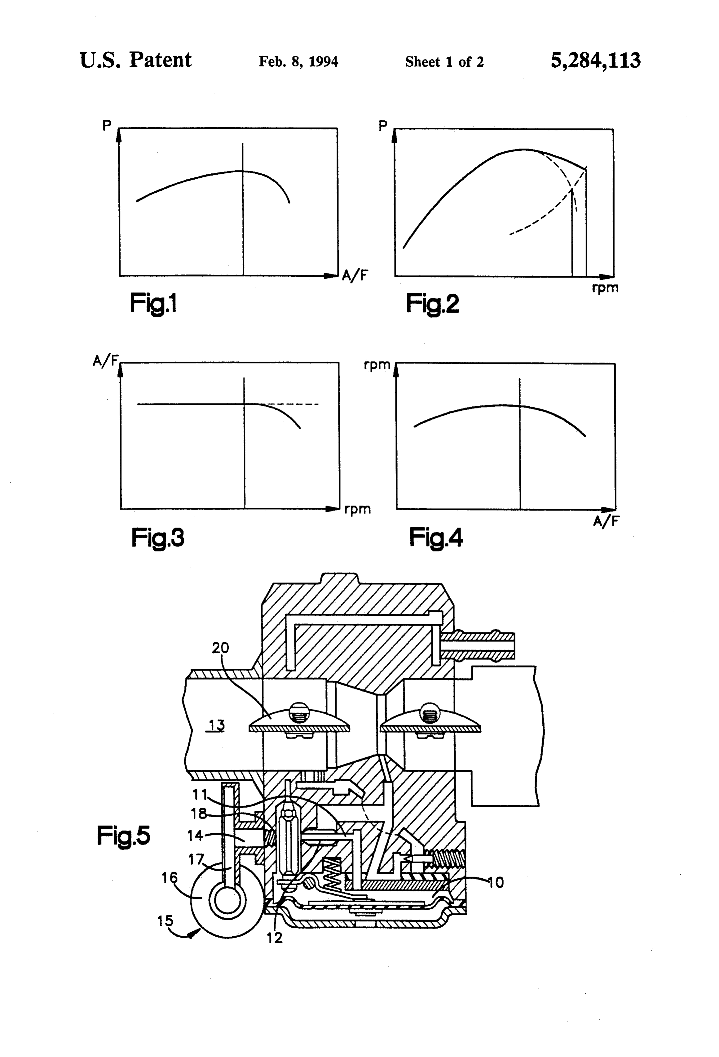
FIG. 5 is a carburetor with an adjusting means for the
ARRANGEMENT IN AN I, C, ENGINE A/F mixture ratio, and
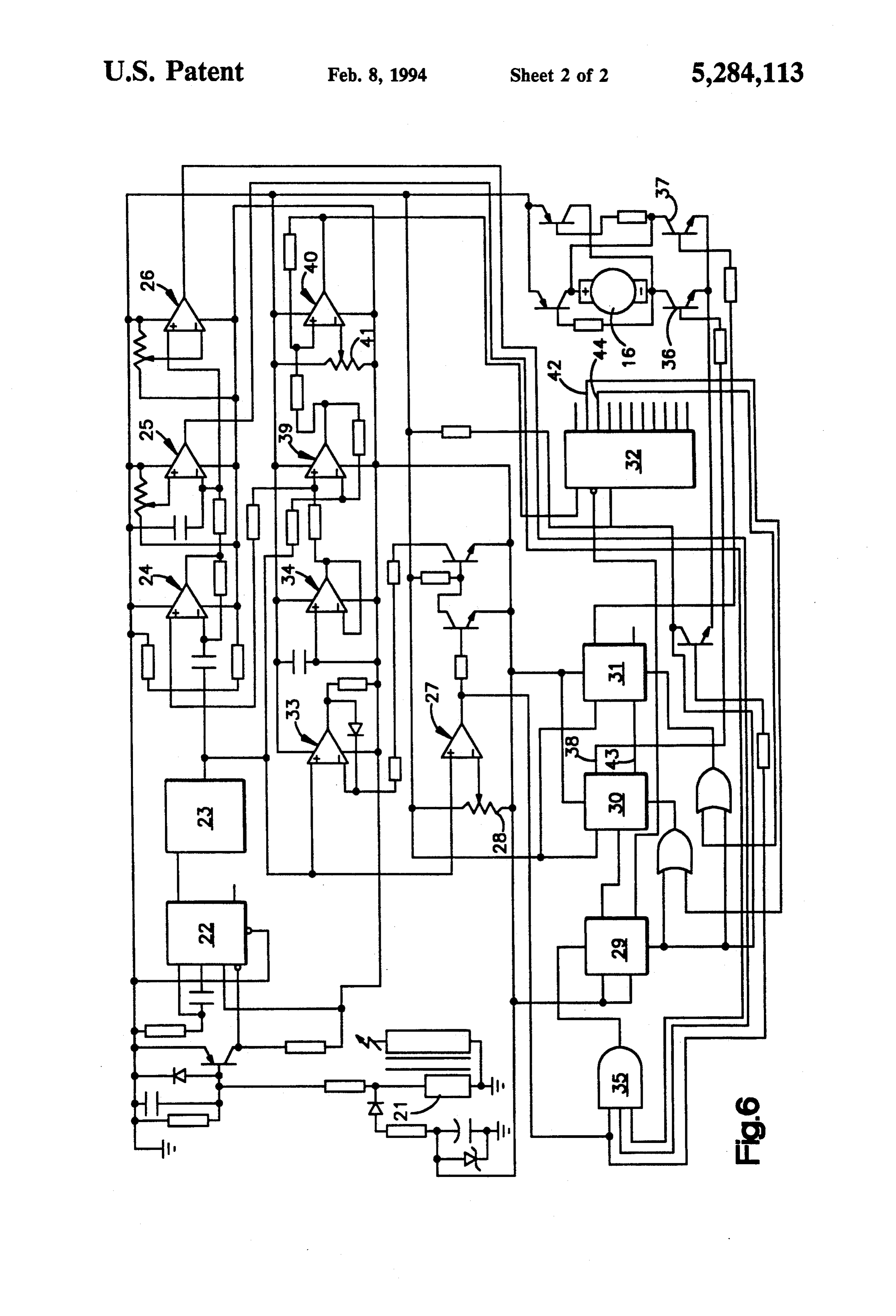
FIG. 6 is a circuit diagram of the arrangement.
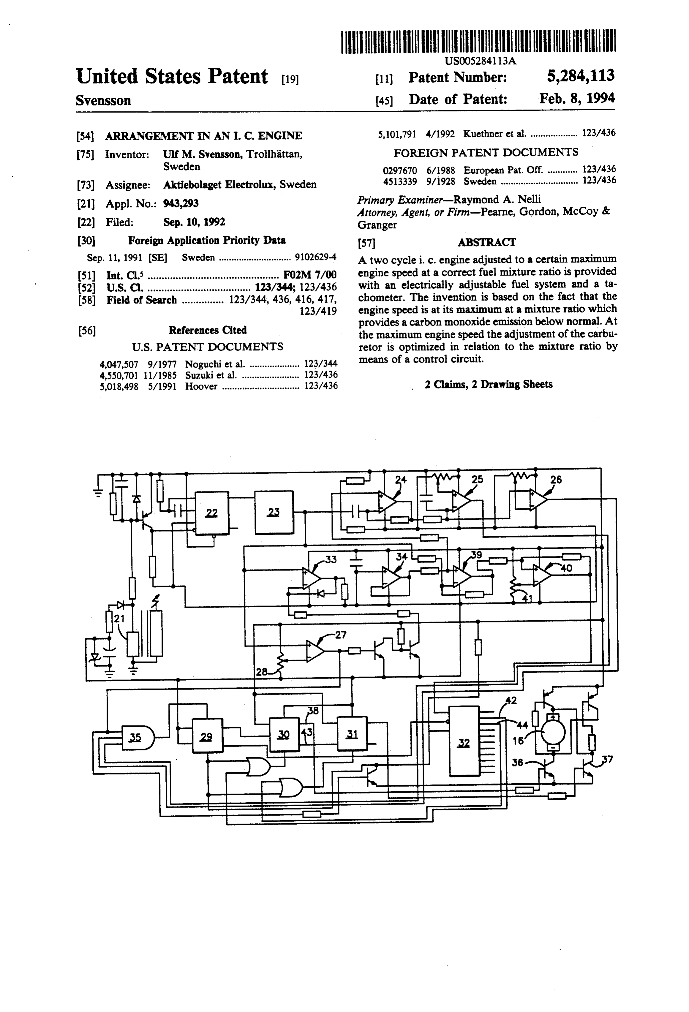
The present invention relates to an arrangement in a An engine can be designed for a limited engine speed two-cycle internal combustion or i, c. engine provided 5 by reducing the time periods available for inlet, flushing with adjusting means for the air/fuel ratio (A/F) and and exhaustion. It is then possible to maintain a correct inlet, flushing, and outlet ports in the cylinder wall, a mixture ratio A/F even at high speed. It is necessary, control unit having a tachometer and control means for however, that the adjustment at maximum speed be electro-mechanical control of the A/F adjusting means, repeated at even intervals to enable the engine to oper and means for determining the maximum engine speed. 10 ate at a correct A/F ratio at all times. This has been The object of the present invention is to provide an made possible due to an electromechanical adjusting arrangement in the carburetor of an i. c. engine for means actuating the fuel nozzle, needle, or fuel passage adjusting the carburetor to the most favourable possible of the carburetor. At runaway engine speed a control air-fuel mixture in order to reduce the emissions of circuit or a computer takes over the duty of optimizing carbon oxide and hydrocarbon. 15 the adjustment at maximum speed. This is obtained by Internal combustion engines produce undesirable the arrangement mentioned in the introduction which emissions of exhaust gases the composition of which is according to the invention is characterized in that the influenced by the air-fuel mixture of the engine. For primary circuit of of the ignition coil of the ignition each engine there is an optimal composition of said system of the engine is utilized as pulse transducer for mixture for providing the lowest possible emissions. An 20 the tachometer, a differential circuit being connected to old and well-known method of adjusting the carburetor said tachometer for providing the derivative of the of, for example, a chain saw engine, is to run the engine engine speed function, and a starting pulse circuit is at full throttle with the friction of the saw chain as load connected to said control means and operable in rela and adjust the mixture ratio of the carburetor so as to tion to digital circuits connected to said differential obtain maximum engine speed. The engine speed is at its 25 circuit and to different branches of said control means maximum at a certain mixture ratio and is decreased at and adapted to increase and reduce said A/F ratio, both richer and leaner mixtures. However, the free respectively, resulting in a corresponding variation of runaway engine speed of modern chain saws is too high the engine speed, and a peak memory being connected to allow this method to be used in practice, from the to said tachometer to provide a final setting of said point of view of safety. The carburetor is therefore 30 adjusting means at said maximum engine speed. normally adjusted such that the engine speed is consid The carburetor of FIG. 5 is a so-called membrane erably below its maximum by setting the mixture ratio carburetor used, for example, in chain saws. A fuel to the rich side. To obtain this the operator must know chamber 10 is filled with fuel which is successively the function of the carburetor adjustment, i.e. which drawn in through a nozzle 11 provided with a nozzle 12 direction of the adjusting screw that provides richer 35 to a through gas passage 13. The needle is an elongation mixture. In order to limit the top speed of a moped a of a shaft 14 of an electromechanic adjusting means 15 tuned exhaust gas pipe has been provided with the re comprising an electric motor 16 and an angled gear 17. sult that the power is drastically reduced at high engine The shaft is threadedly engaged in a bore 18 in the speed, and the maximum engine speed is consequently carburetor housing whereby a rotation by means of the reduced, too. In this case the engine has a gas dynamic electronic motor results in a displacement of the needle tuning and an overrich combustion gas need not be used in the opening of the nozzle. The fuel flow through the to keep the engine speed down. nozzle is thereby controlled. The invention provides an arrangement for automatic By reducing the time periods available at the ports for adjustment of the carburetor in which the maximum of inlet, flushing and exhaustion until an appropriate maxi the engine speed, but not its absolute value, is used as 45 mum engine speed is obtained it is possible to maintain control parameter. The theory of the operation of the a constant mixture ratio even at an engine speed ap arrangement is best described by the following figures proaching this maximum speed (FIG. 3). illustrating various parameters of a small two cycle The adjusting needle 12 of the fuel nozzle and the engine. shaft 14 can be made as a self-braking screw. It is ro FIG. 1 illustrates the variation of the output power of SO tated by the electric motor which in turn is controlled the engine in relation to the mixture ratio A/F. The by a control unit 19 or a computer. The control unit optimal power adjustment occurs at the top of the optimizes the fuel amount during a sufficiently long graph. period of free rush with the gas throttle fully open so FIG. 2 shows the variation of the output power in that a maximum engine speed is reached. The speed is relation to the engine speed. The continuous graph 55 metered by an electronic tachometer 21 connected to applies to a correct A/F and the dotted to an enriched the ignition system. As the shaft 14 is self-braking the adjustment. The Figure also has a dashed line showing performed setting will be maintained when the engine is the load (the friction of the saw chain) which at the disconnected from the control unit. The carburetor intersections of the graphs shows the respective run maintains this setting until the next adjustment even if away engine speeds. the engine is shut off and the system becomes current FIG. 3 illustrates a carburetor characteristic which less.
according to the above is necessary in modern engines For the sake of completeness FIG. 6 shows a diagram having a high engine speed. The dashed line shows a of the control unit with the drive circuit for the electric constant A/F and the continuous line the enriched car motor. The diagram shows a connection based on ana buretor adjustment providing a lower engine speed. 65 log and digital components. A control unit for maxi FIG. 4 shows the engine speed varies with A/F. The mum speed calibration is shown which is connected to top portion of the graph shows the maximum engine the ignition coil of the engine (magnetic ignition sys power. tem) in which the primary winding 21 provides the
Page 5
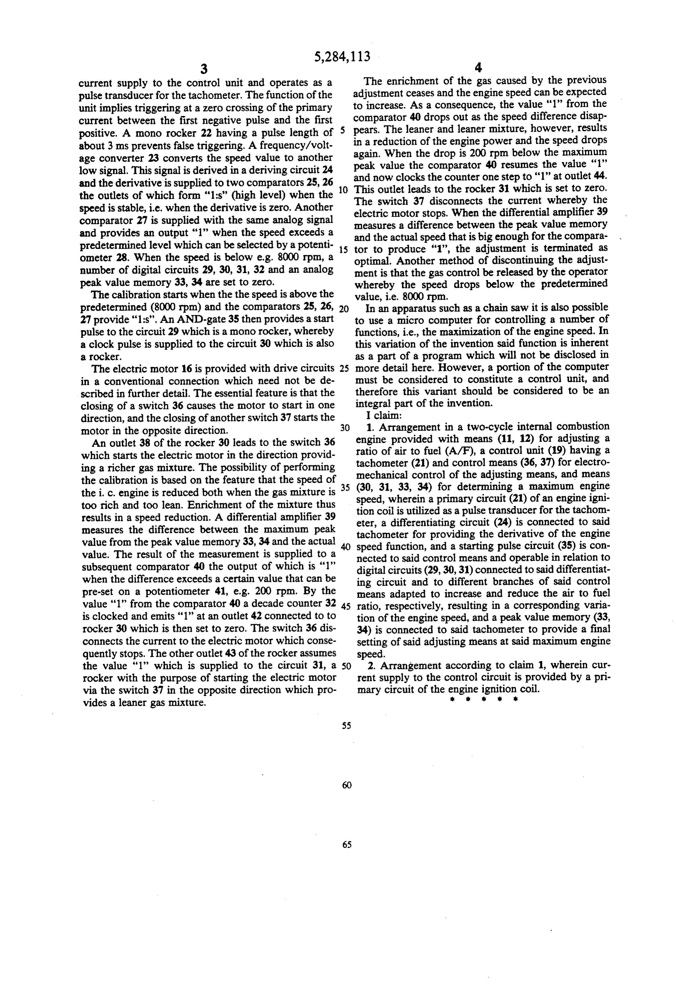
current supply to the control unit and operates as a The enrichment of the gas caused by the previous pulse transducer for the tachometer. The function of the adjustment ceases and the engine speed can be expected unit implies triggering at a zero crossing of the primary to increase. As a consequence, the value "1" from the current between the first negative pulse and the first 5 comparator 40 drops out as the speed difference disap positive. A mono rocker 22 having a pulse length of pears. The leaner and leaner mixture, however, results in a reduction of the engine power and the speed drops about 3 ms prevents false triggering. A frequency/volt again. When the drop is 200 rpm below the maximum age converter 23 converts the speed value to another peak value the comparator 40 resumes the value "1" low signal. This signal is derived in a deriving circuit 24 and the derivative is supplied to two comparators 25, 26 10 and now clocks the counter one step to "1" at outlet 44. This outlet leads to the rocker 31 which is set to zero.
the outlets of which form "1:s' (high level) when the The switch 37 disconnects the current whereby the speed is stable, i.e. when the derivative is zero. Another electric motor stops. When the differential amplifier 39 comparator 27 is supplied with the same analog signal measures a difference between the peak value memory and provides an output '1' when the speed exceeds a and the actual speed that is big enough for the compara predetermined level which can be selected by a potenti 15 tor to produce "1", the adjustment is terminated as ometer 28. When the speed is below e.g. 8000 rpm, a optimal. Another method of discontinuing the adjust number of digital circuits 29, 30, 31, 32 and an analog ment is that the gas control be released by the operator peak value memory 33, 34 are set to zero. whereby the speed drops below the predetermined The calibration starts when the the speed is above the value, i.e. 8000 rpm.
predetermined (8000 rpm) and the comparators 25, 26, 20 In an apparatus such as a chain saw it is also possible 27 provide "1:s'. An AND-gate 35 then provides a start to use a micro computer for controlling a number of pulse to the circuit 29 which is a mono rocker, whereby functions, i.e., the maximization of the engine speed. In a clock pulse is supplied to the circuit 30 which is also this variation of the invention said function is inherent a rocker. as a part of a program which will not be disclosed in The electric motor 16 is provided with drive circuits 25 more detail here. However, a portion of the computer in a conventional connection which need not be de must be considered to constitute a control unit, and scribed in further detail. The essential feature is that the therefore this variant should be considered to be an closing of a switch 36 causes the motor to start in one integral part of the invention.
direction, and the closing of another switch 37 starts the 30 1.I claim:
Arrangement in a two-cycle internal combustion motor in the opposite direction.
An outlet 38 of the rocker 30 leads to the switch 36 engine provided with means (11, 12) for adjusting a ratio of air to fuel (A/F), a control unit (19) having a which starts the electric motor in the direction provid tachometer ing a richer gas mixture. The possibility of performing mechanical (21) and control means (36, 37) for electro the calibration is based on the feature that the speed of 35 (30, 31, 33, 34) forofdetermining control the adjusting means, and means a maximum engine the i, c. engine is reduced both when the gas mixture is speed, wherein a primary circuit (21) of an engine igni too rich and too lean. Enrichment of the mixture thus results in a speed reduction. A differential amplifier 39 eter,coil tion is utilized as a pulse transducer for the tachom a differentiating circuit (24) is connected to said measures the difference between the maximum peak tachometer for providing the derivative of the engine value from the peak value memory 33, 34 and the actual speed function, and a starting pulse circuit (35) is con value. The result of the measurement is supplied to a nected to said control means and operable in relation to subsequent comparator 40 the output of which is "1" digital circuits (29, 30, 31) connected to said differentiat when the difference exceeds a certain value that can be ing circuit and to different branches of said control pre-set on a potentiometer 41, e.g. 200 rpm. By the means adapted to increase and reduce the air to fuel value "1" from the comparator 40 a decade counter 32 45 ratio, respectively, resulting in a corresponding varia is clocked and emits '1' at an outlet 42 connected to to tion of the engine speed, and a peak value memory (33, rocker 30 which is then set to zero. The switch 36 dis 34) is connected to said tachometer to provide a final connects the current to the electric motor which conse setting of said adjusting means at said maximum engine quently stops. The other outlet 43 of the rocker assumes speed.
the value "1" which is supplied to the circuit 31, a 50 2. Arrangement according to claim 1, wherein cur rocker with the purpose of starting the electric motor rent supply to the control circuit is provided by a pri via the switch 37 in the opposite direction which pro mary circuit of the engine k .
ignition
coil.
vides a leaner gas mixture.
Page 6
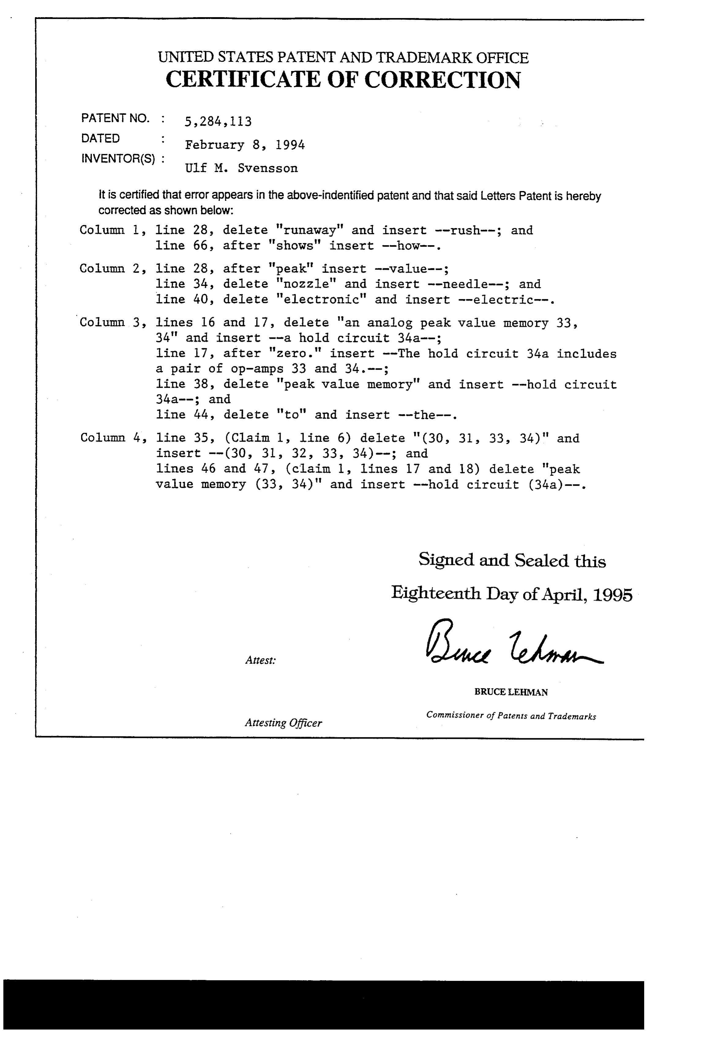
UNITED STATES PATENT AND TRADEMARK OFFICE
CERTIFICATE OF CORRECTION
INVENTOR(S) : Ulf M. Svensson it is certified that error appears in the above-indentified patent and that said Letters Patent is hereby Corrected as shown below:
Column l, line 28, delete "runaway' and insert --rush-; and line 66, after "shows" insert -how--.
Column 2, line 28, after "peak' insert --value--; line 34, delete "nozzle" and insert --needle-; and line 40, delete "electronic" and insert --electric-. Column 3, lines 16 and 17, delete "an analog peak value memory 33, 34" and insert --a hold circuit 34a-;
line 17, after "zero." insert --The hold circuit 34a includes a pair of op-amps 33 and 34.--;
line 38, delete "peak value memory" and insert -hold circuit
line 44, delete "to" and insert --the--.
Column 4, line 35, (Claim 1, line 6) delete "(30, 31, 33, 34)" and
lines 46 and 47, (claim 1, 1ines 17 and 18) delete "peak value memory (33, 34)' and insert -hold circuit (34a)--.
Signed and Sealed this
Eighteenth Day of April, 1995
BRUCELEHMAN
Commissioner of Patents and Trademarks
Attesting Officer
Provenance
- Collection
- Cited prior art
- Original PDF
- patentimages.storage.googleapis.com →
- Filed
- 1992-09-10
- Pages
- 6
- Method
- pdftotext (the PDF's own text layer) + pdftoppm 300dpi page scans
- Source
- Google Patents bibliographic record
- Granted
- 1994-02-08
- Inventors
- Ulf M. Svensson; Electrolux AB
- Transcribed from
- patentimages.storage.googleapis.com →