patent · US5282497
Fuel delivery and vapor control system for controlling the release of fuel vapors from a vehicle fuel tank
1 February 1994
Page 1 — bibliographic record
O US005282497A United States Patent (19) 11) Patent Number: 5,282,497 Allison (45) Date of Patent: Feb. 1, 1994 (54) FUELDELIVERY AND WAPOR CONTROL 5,054,528 10/1991 Saitoh ................................... 141/59 SYSTEM FOR CONTROLLING THE 5, 183,087 2/1993 Aubel et al. .......................... 141/59 RELEASE OF FUEL VAPORS FROM A in ar- ick VEHICLE LTANK Primary Examiner-Ernest G. Cusic
Attorney, Agent, or Firm-Harness, Dickey & Pierce 76 Inventor: Allen Allison, 5437. Whitehall, W. 57 ABSTRACT Bloomfield, Mich. 48323
A fuel and vapor control system for motor vehicle (21) Appl. No.: 965,233 applications is disclosed. The fuel and vapor control 22 Filed: Oct. 23, 1992 system regulates the refueling operation to maintain a sufficient vapor dome within the motor vehicle fuel (51) Int. Cl. ....................... B65B 31/00; F16K 24/00 tank to prevent over-filling thereof upon malfunction of 52 U.S.C. ........................................ 141/59; 141/45; a fuel nozzle's automatic shut-off mechanism. The fuel
and vapor control system includes a first valve assembly for controlling the flow of fuel vapors to a vapor cap 137/587-589, 39, 43; 55/88, 587; 141/3. ture device, a second valve assembly for controlling actuation of the nozzle shut-off mechanism, and a third (56) References Cited valve assembly for controlling the delivery of liquid fuel into the fuel tank in response to actuation of the first
4,699,638 i0/1987 Harris ................................. 55/88 X inhibits the emission of evaporative fuel vapors upon 4,724,861 2/1988 Covert et al. . 141/59 X withdrawal of the nozzle from the fill pipe. The various
:s valve assemblies cooperate to inhibit leakage of liquid 4,874,020 10/1989 Bucci.....................................14/46X
E, fuel and vapors from the motor vehicle fuel system upon impact and/or the occurrence of a roll-over situa
4,974,645 12/1990 Johnson .......... 141/59 ton.
5,014,742 5/1991 Covert et al. ... 137/588 5,054,508 10/1991 Benjey .................................. 137/43 30 Claims, 7 Drawing Sheets
Page 2
Drawing sheet — no readable text.
Page 3
Drawing sheet — no readable text.
Page 4
Drawing sheet — no readable text.
Page 5
Drawing sheet — no readable text.
Page 6
Drawing sheet — no readable text.
Page 7
Drawing sheet — no readable text.
Page 8
Drawing sheet — no readable text.
Page 9
during vehicle operation and/or contamination of the
FUEL DELIVERY AND WAPOR CONTROL activated charcoal canister. In addition, lack of an ade SYSTEM FOR CONTROLLING THE RELEASE OF quate "vapor dome' within the fuel tank can also cause FUEL WAPORS FROM A VEHICLE FUELTANK excessively high tank pressures due to extreme varia
BACKGROUND OF THE INVENTION
tions in the fuel temperature and volatility.
The present invention relates generally to motor ve SUMMARY OF THE INVENTION hicle fuel filling systems and, more particularly, to a fuel Accordingly, it is a primary object of the present and vapor control system for controlling the release of 10 invention to meet all of the above named fuel filling evaporative and running loss fuel vapors into the atmo system requirements while overcoming the various sphere. disadvantages associated with conventional systems. In In view of stringent environmental and safety regula a related object, the present invention is directed to a tions which significantly restrict the emission of non vapor control system provided for substantially mini combusted hydrocarbons (i.e. fuel vapors) into the at 15 mizing the escape of "evaporative' and "running loss' mosphere, emission control systems are incorporated into modern motor vehicles. These systems are adapted fuelAnothervapors from the fuel system. object of the present invention is to provide to prevent or substantially minimize the release of fuel a motor vehicle fuel and vapor control system that vapors from the fuel tank and/or the fuel intake system conforms to all governmental, environmental and safety of an internal combustion engine. Most conventional 20 regulations regarding evaporative and refueling emis emission control systems use a vapor capture device, such as an activated charcoal canister, for absorbing or sions, and vehicle impact, while generating enhanced "trapping' evaporative emissions when the engine is customer satisfaction.
shut off. Upon starting of the engine, the flow offiltered According to a preferred embodiment of the present air through the charcoal canister purges the vapors invention, the fuel and vapor control system is adapted therefrom such that the vapors are delivered to the 25 to regulate the refueling operation for maintaining a intake system for combustion by the engine. sufficient "vapor dome' within the fuel tank to prevent Unfortunately, vapor control systems incorporated over-filling of the fuel tank upon malfunction of the into modern motor vehicles have become increasingly nozzle's automatic shut-off mechanism. More particu complex and expensive due to a number of critical de larly, the fuel and vapor control system of the present sign requirements. First, the fuel filling system must 30 invention includes first valve means for controlling the prevent leakage of fuel and vapors during both refuel ing and normal operation of the vehicle. In addition, the flow of fuel vapors to a vapor capture device, second valve means for controlling actuation of the nozzle fuel filling system must allow for the entry of air to shut-off mechanism, third valve means for controlling replace the fuel within the fuel tank as it is consumed, the delivery of liquid fuel into the fuel tank in response and must also allow for venting of over-pressure condi 35 to actuation of the first and second valve means, and tions within the tank. The fuel filling system must also provide means for actuating the automatic shut-off fourth valve means associated with a fill pipe restrictor mechanism incorporated in fuel dispensing nozzles. assembly for inhibiting the emission of evaporative fuel Furthermore, the fuel filling system must inhibit the vapors upon withdrawal of the nozzle therefrom. Fur leakage of liquid fuel and vapors upon impact and dur thermore, the first, second, third and fourth valve ing the occurrence of a "roll-over” accident. Finally, means cooperate to inhibit leakage of liquid fuel and modern fuel filling systems must prevent the introduc vapors from the motor vehicle fuel system upon impact tion of leaded fuels into the fuel tank of the vehicle. and/or the occurrence of a roll-over accident. Conventional fuel filling and vapor control systems Additional objects, features, and advantages of the permit pressurized fuel vapors present within the motor 45 present invention will become apparent to those skilled vehicle fuel system to escape to the atmosphere upon in the art upon consideration of the following detailed removal of the fuel cap. It will be appreciated that a description of the preferred embodiments exemplifying significant quantity of otherwise combustible fuel is lost the best mode of carrying out the invention as presently to the atmosphere each time a vehicle is refueled. In perceived.
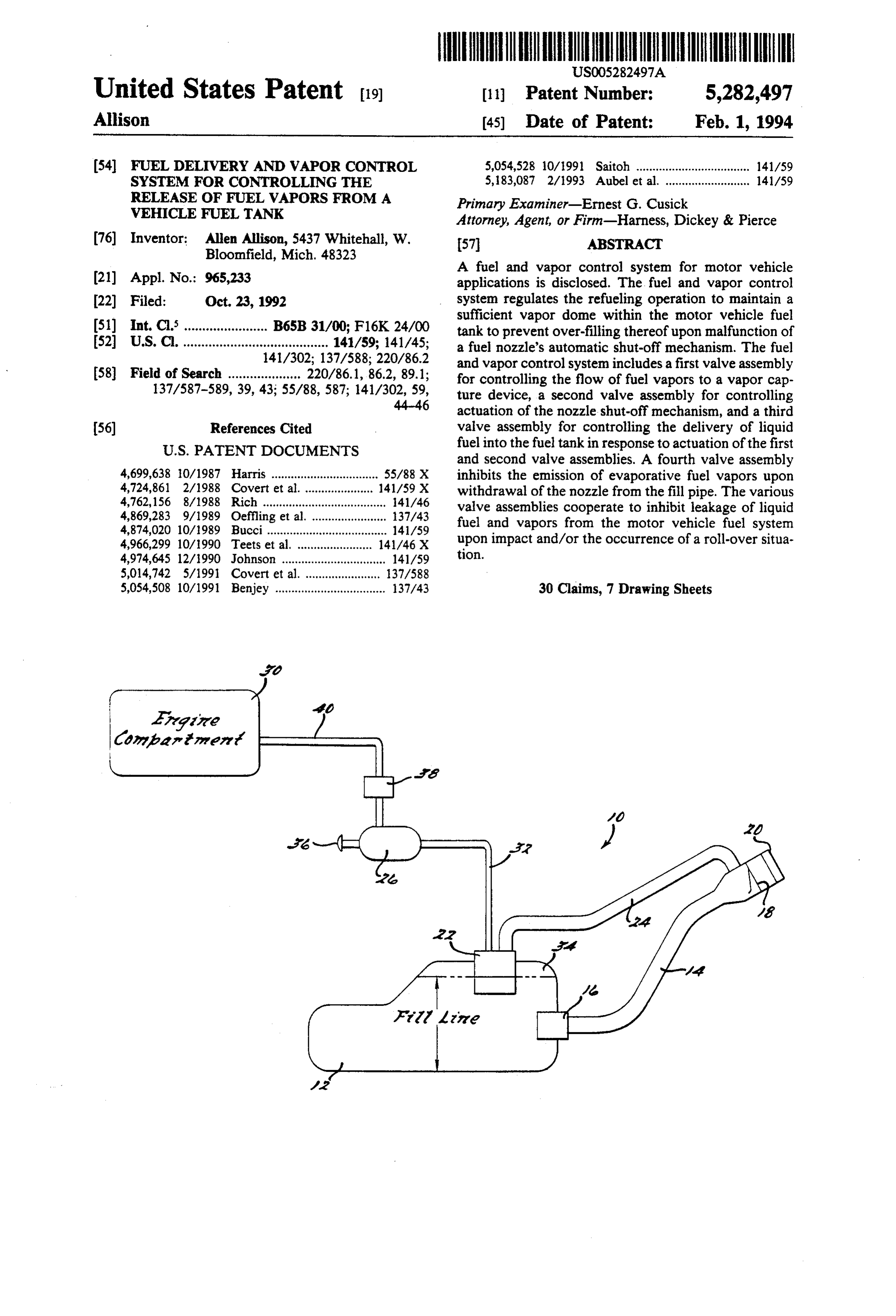
addition, new fuel vapors are continually generated 50 during refueling due to splash and agitation of the dis BRIEF DESCRIPTION OF THE DRAWINGS pensed fuel, as well as from extreme temperature differ FIG. 1 is a diagrammatic view of a motor vehicle fuel ences between the fuel in the fuel tank and the newly system dispensed fuel. Furthermore, as liquid fuel is delivered arrangedincorporating a fuel and vapor control system into the fuel tank, fuel vapors are displaced from the the present invention; a first preferred embodiment of
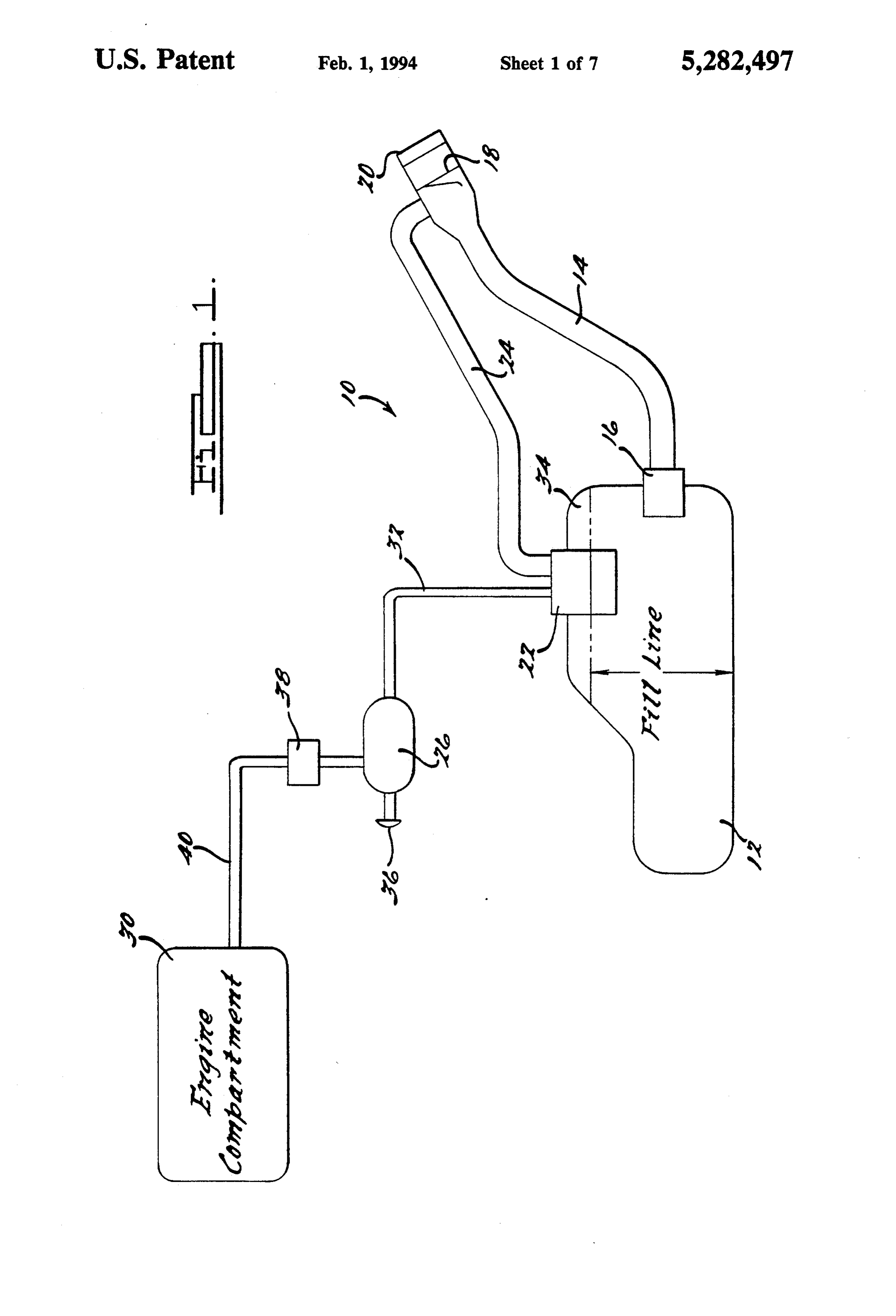
fuel tank's vapor space and are typically released di FIG. 2 is a top elevational view of a control valve rectly into the atmosphere through the fuel tank filler neck. assembly associated with the fuel and vapor control Another drawback associated with most conven system of FIG. ;
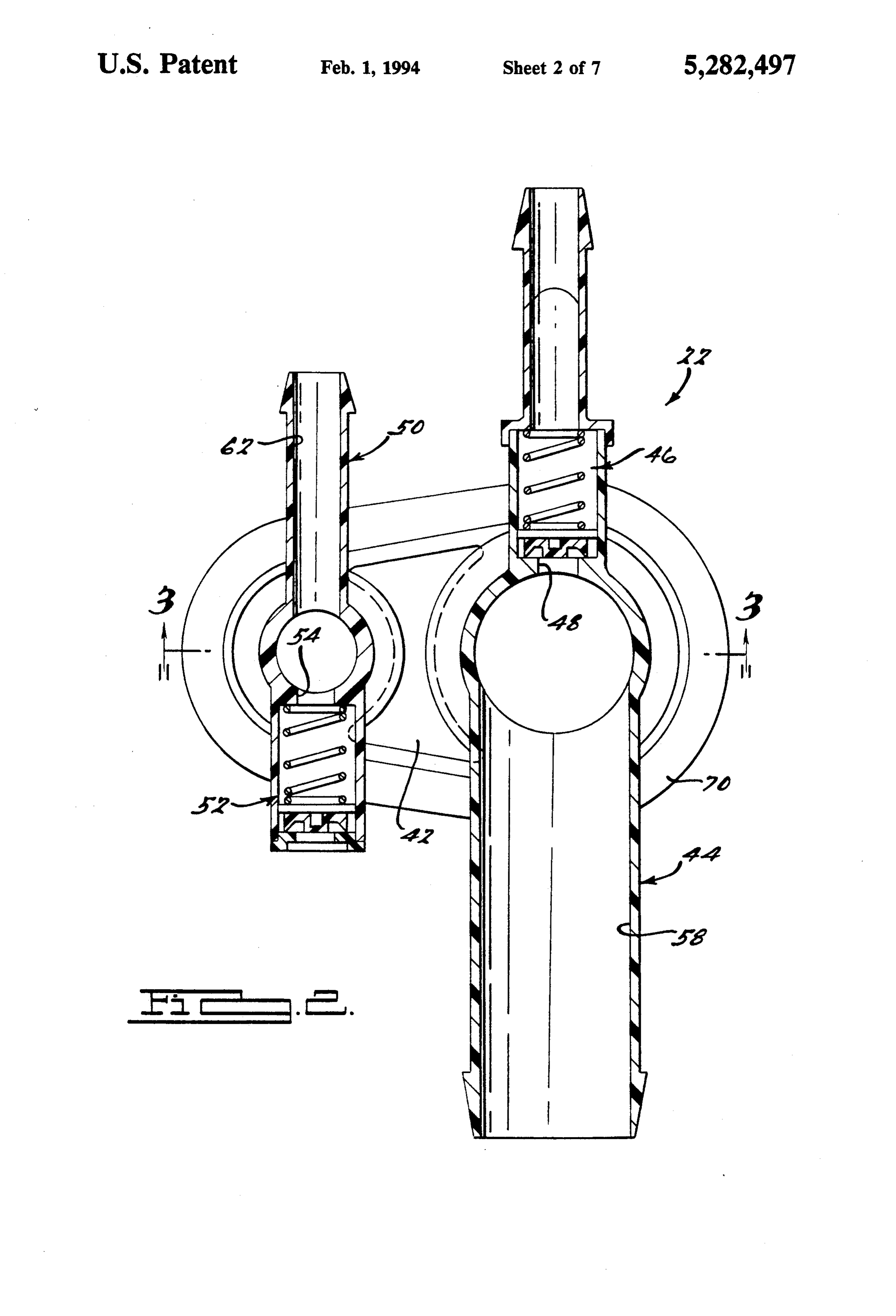
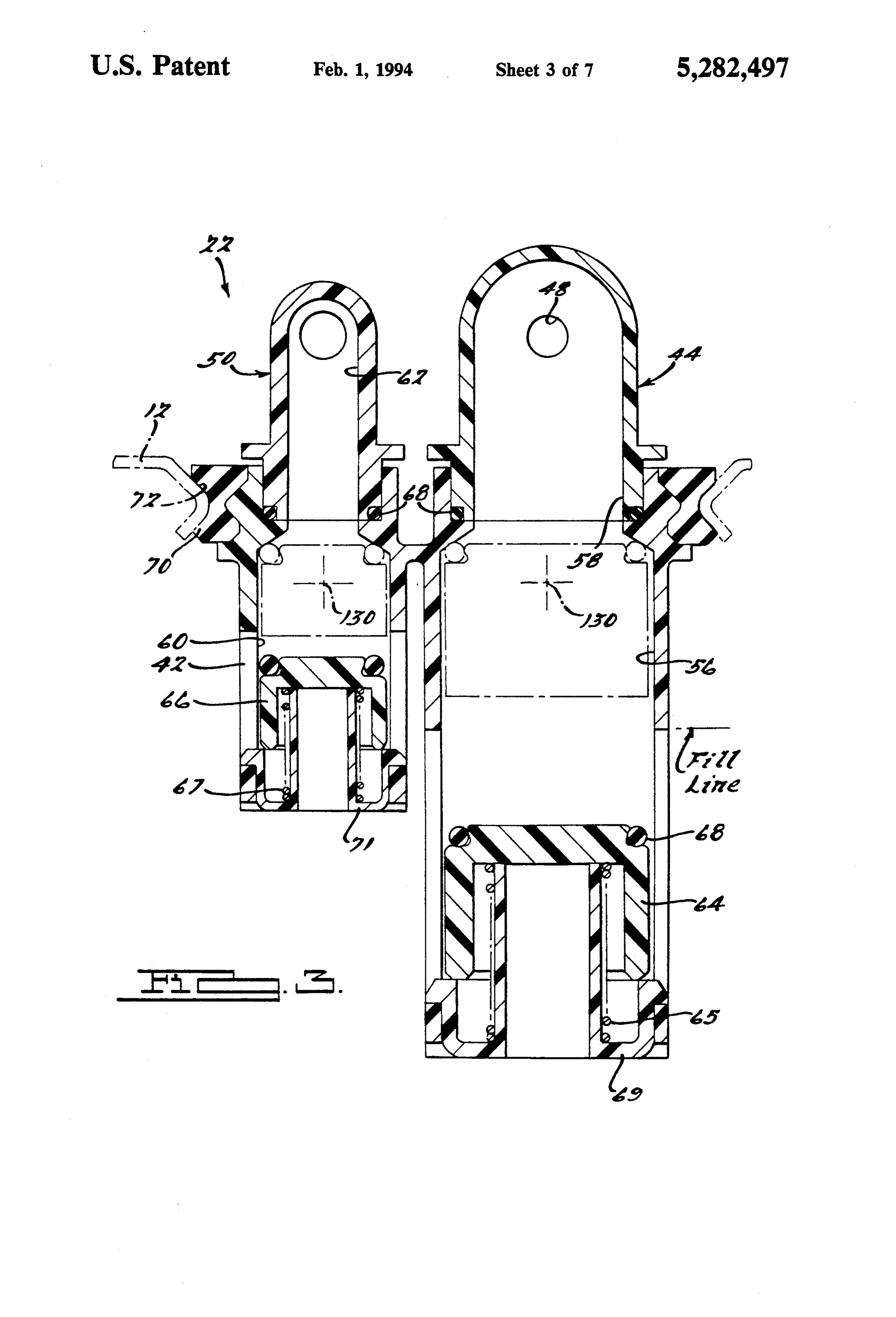
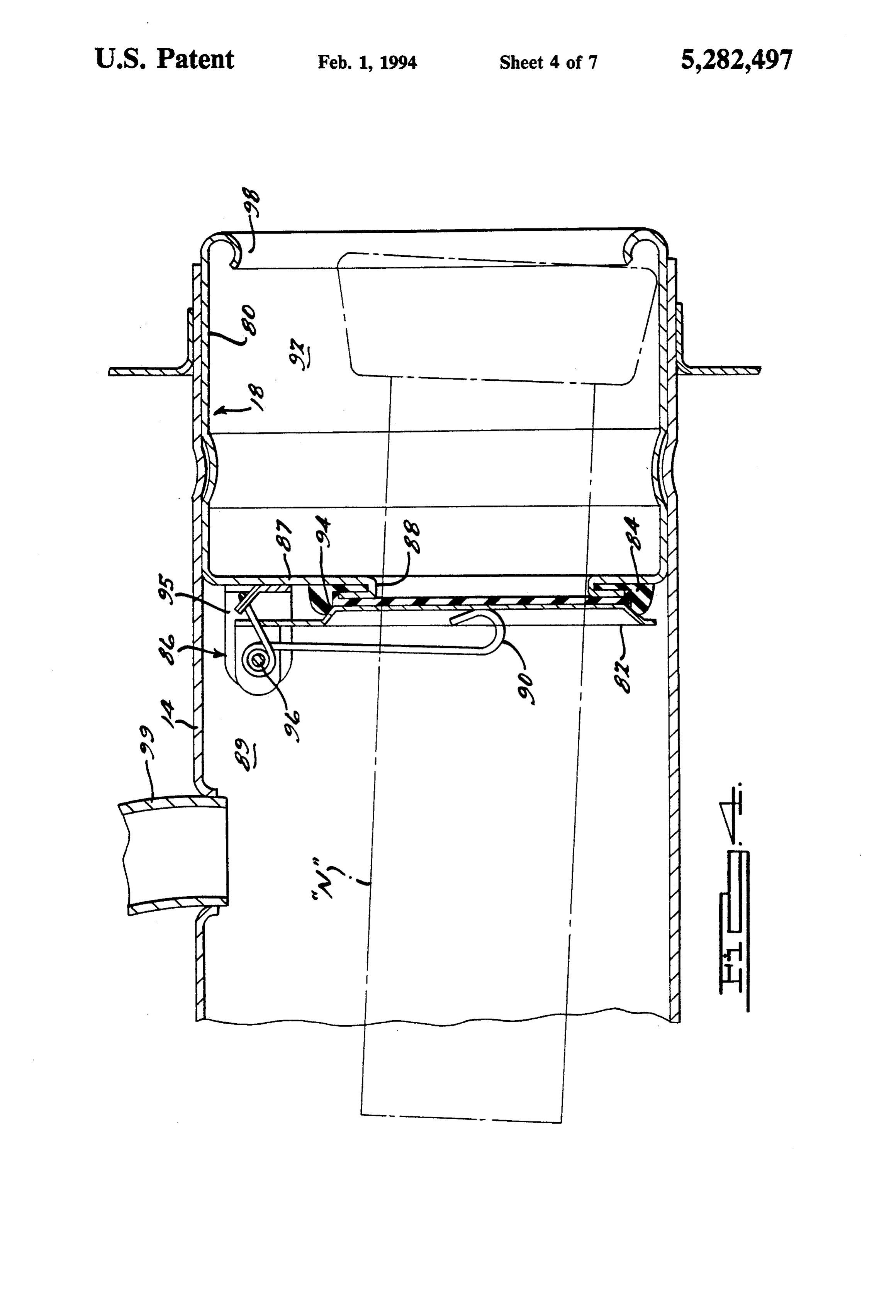
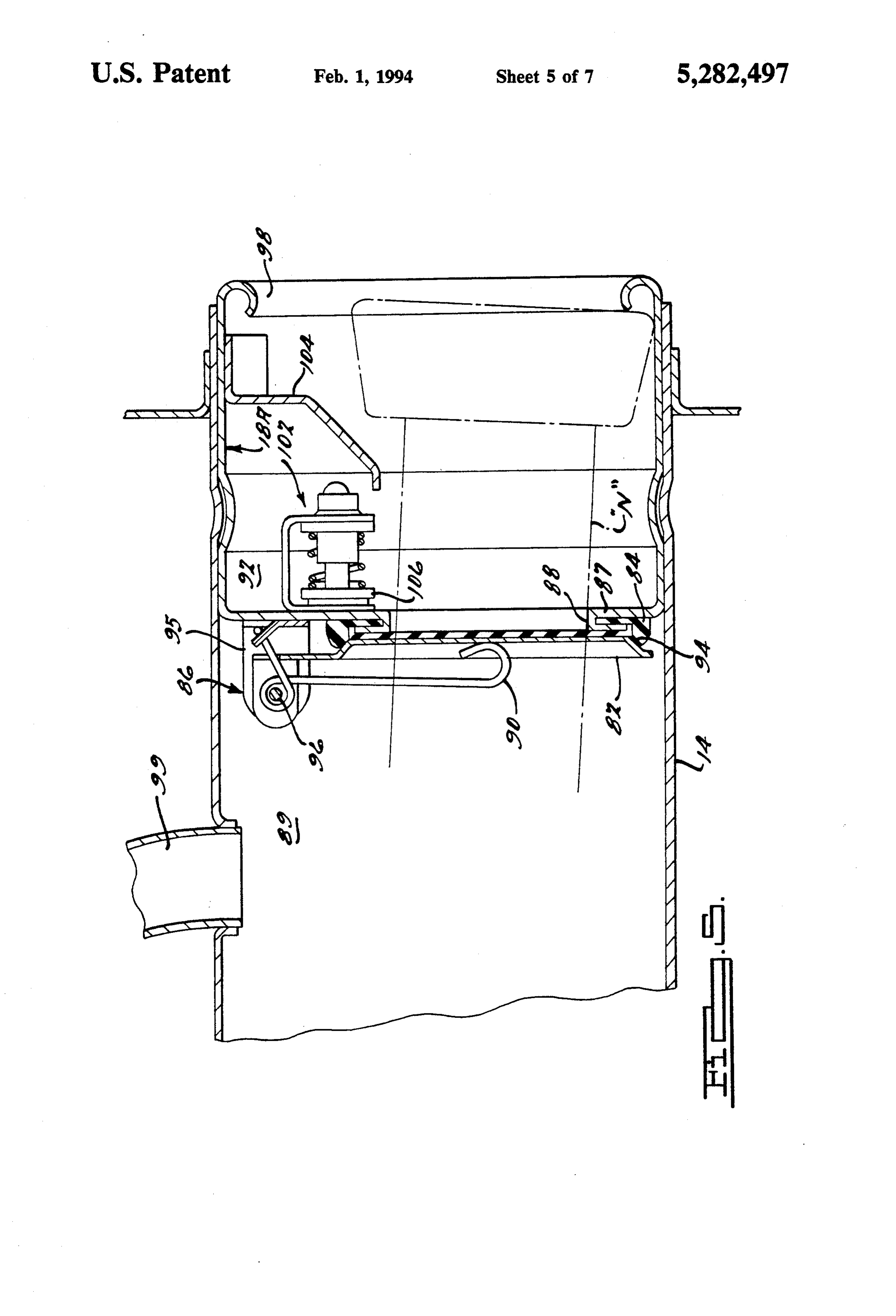
tional fuel filling systems is that over-filling of the fuelFIG. 3 is a section view of the control valve assembly tank is not monitored and regulated. If the nozzle shut taken along line 3-3 of FIG. 2; off mechanism fails to terminate delivery of liquid fuel FIG. 4 is a section view of a cap-less restrictor assem into the fuel tank, fuel will eventually back-up the fill bly secured to one end of the fill pipe incorporated into pipe and spill onto the ground for alerting the operator the fuel and vapor control system of FIG. 1; to manually shut-off the nozzle. However, such over 65 FIG. 5 is a section view, similar to FIG. 4, illustrating filling of the fuel tank displaces the required "vapor an alternative embodiment of a cap-less restrictor as dome' located above the desired maximum fill level of sembly for use in the fuel and vapor control system of the fuel tank which can potentially cause fuel leakage FIG. 1;
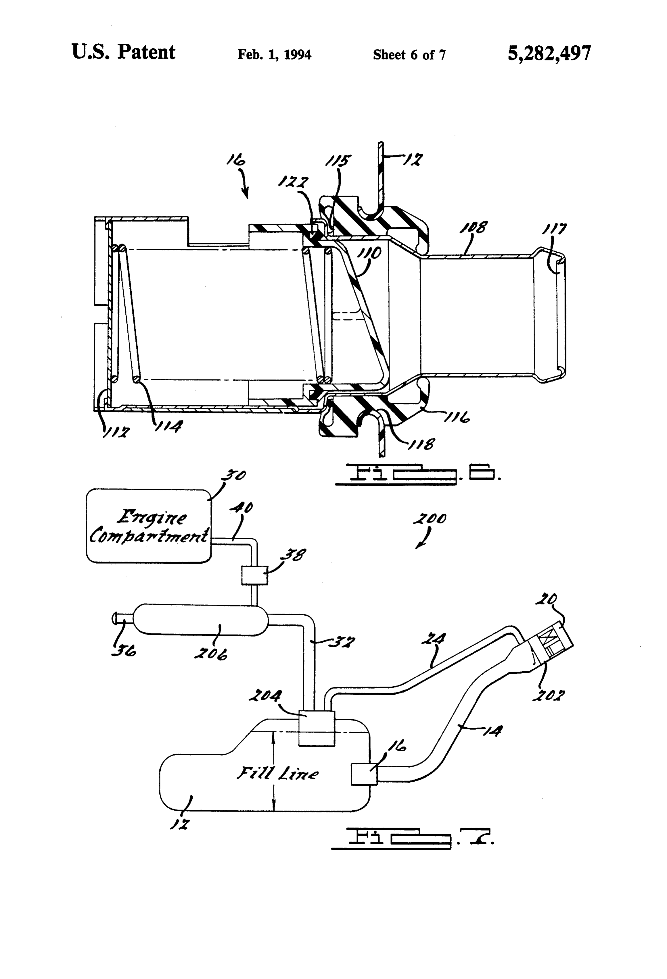
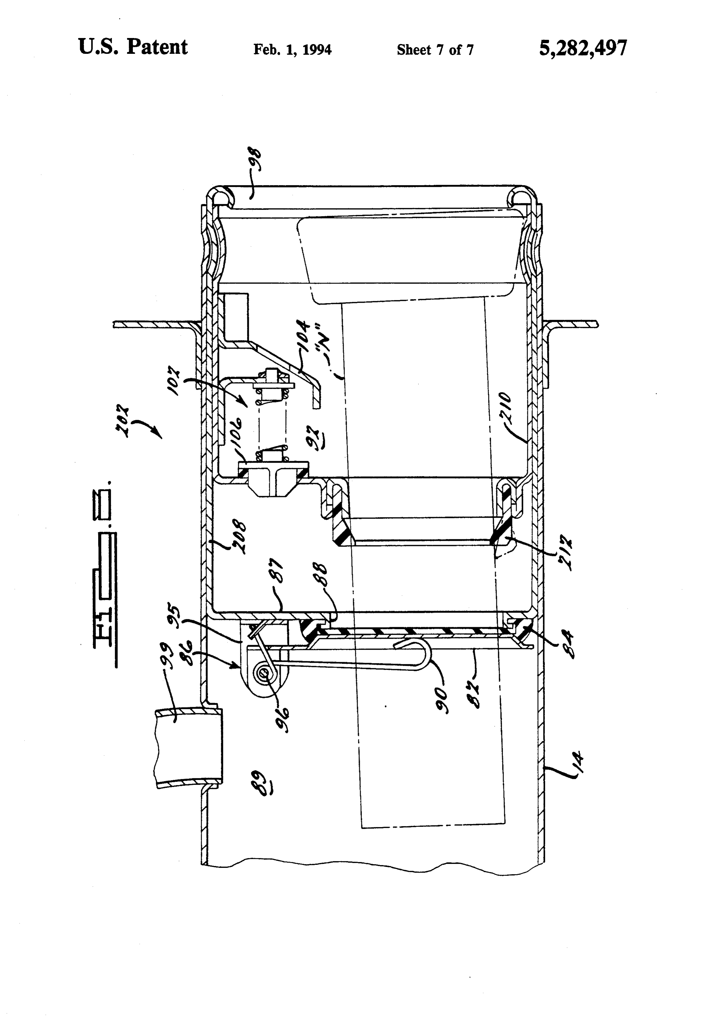
Page 10
FIG. 6 is a section view of a tank spud assembly 12. As best seen from FIGS. 2 and 3, control valve provided for interconnecting a second end of the fill assembly 22 includes a main housing 42, nozzle signal pipe to the fuel tank; fitting 44, a pressure relief valve assembly 46 which is FIG. 7 is a diagrammatic view of a motor vehicle fuel supported within a pressure relief port 48 formed in system incorporating a fuel and vapor control system nozzle signal 44, a canister fitting 50, a vacuum relief arranged according to a second preferred embodiment valve assembly 52 which is supported within a vacuum of the present invention; and relief port 54 formed in canister fitting 50, and valve FIG. 8 is a section view of a modified cap-less restric means for controlling the flow of fuel vapors from tor assembly incorporated into the fuel and vapor con vapor dome 34 into fittings 44 and 50, respectively. trol system of FIG. 7. 10 In general, control valve assembly 22 functions as
DETAILED DESCRIPTION OF THE
two independent "normally open' valve assemblies for
PREFERRED EMBOOMENTS controlling the flow of fuel vapors within vapor dome 34 between a first flow passage 56 and a nozzle signal
With particular reference to FIGS. 1 through 6, a port 58, and between a second flow passage 60 and a first preferred embodiment of a fuel vapor and control 15 canister port 62. More particularly, nozzle signal port system 10 (hereinafter referred to as control system 10) 58 is coupled to a first end of nozzle signal line 24. is disclosed. As is diagrammatically shown in FIG. 1, Pressure relief port 48 is fluidly connected to a first end control system 10 includes a fuel tank 12, a fill pipe 14, of a leak line (not shown) the second end of which is a tank spud assembly 16, a cap-less restrictor assembly preferably connected inside the fender area of the 18, a dirt cover 20, a control valve assembly 22 and a 20 motor vehicle for permitting limited fuel and vapor nozzle signal conduit or line 24. Control system 10 is leakage upon actuation of pressure relief valve assembly adapted to be operatively connected to a vapor recov 46. Pressure relief valve assembly 46 is a safety feature ery device 26 and an internal combustion engine 30 via which permits excessive pressure within fuel tank 12 to a vapor conduit or line 32. Vapor line 32 provides a be vented through relief port 48. More specifically, fluid communication path between the fuel vapor pres 25 pressure relief valve 46 is a normally closed valve appa ent in a vapor dome 34 of fuel tank 12 and vapor recov ratus which is opened in response to the tank pressure ery device 26 for eventual transfer to the fuel intake acting thereon when the pressure exceeds a predeter system of engine 30, Vapor dome 34 allows the fuel mined level.
stored in fuel tank 12 to expand due to temperature and Canister port 62 is adapted to be connected to a first volatility variations without causing an over-pressure 30 end of vapor line 32. The second end of vapor line 32 is condition therein. It is to be understood that the phrase connected to charcoal canister 26. Vacuum relief valve "fluid communication' is intended to indicate the trans assembly 52 is provided to permit fresh air to enter relief fer of at least one of the liquid fuel and the fuel vapor. port 54 for purging vapors from canister port 62 while In general, control system 10 is operable to transfer a preventing the escape of vapors therethrough to the substantial portion of the evaporative fuel vapors dis 35 atmosphere. It will be appreciated, that pressure relief placed by liquid fuel delivered to fill tank 12 and/or valve assembly 46 and vacuum relief valve assembly 52 generated during refueling to vapor recovery device 26 can be of any suitable type currently known in the art. for permitting substantially complete combustion in With particular reference now to FIG. 3, the valve engine 30. In addition, control system 10 includes means means of control valve assembly 22 includes roll over for permitting "running loss' vapors to be routed to /over-fill valve members 64 and 66, respectively, which vapor recovery device 26. Running loss vapors are are supported within housing 42 for movement between those fuel vapors generated by the fuel splashing around a "normally open' position and a "closed" position. within fuel tank 12 during normal operation of the More specifically, in the normally open position roll motor vehicle. In this manner, the pressure of the va over/over-fill valve member 64 permits fuel vapors pors within vapor dome 34 can be regulated during 45 stored in vapor dome 34 to flow from first flow passage operation of the motor vehicle. 56 to signal port 58 and, in the closed position valve Preferably, vapor recovery device 26 is a sealed can member 64 inhibits the flow of vapors therebetween. ister filled with activated charcoal that is normally Likewise, in the open position roll-over/over-fill valve vented to the atmosphere via vent 36. The large surface member 66 permits vapors stored in vapor dome 34 to area of the charcoal absorbs the hydrocarbons in the SO flow from second flow passage 60 to canister port 62 fuel vapors, while allowing the air to escape through while inhibiting flow therebetween when valve member vent 36. Furthermore, a purge line 40 provides a fluid 66 is in the closed position.
communication path between charcoal canister 26 and Valve members 64 and 66 are independently dis the intake manifold vacuum of internal combustion placed toward the closed position by the rising level of engine 30 and is selectively controlled by a flow control 55 liquid fuel within fuel tank 12 or upon excessive angular valve 38. When the flow control valve 38 is closed, movement of control valve assembly 22 (i.e. upon roll canister 26 absorbs the fuel vapors drawn from vapor over). In addition, biasing means, shown as first and dome 34. When flow control valve 38 is open, the ab second coil springs 65 and 67, are provided intermediate sorption process is reversed such that the manifold stationary retainers 69 and 71 for exerting a biasing vacuum draws fresh air in through canister vent 36 and force on valve members 64 and 66, respectively. past the charcoal, for releasing the absorbed hydrocar An annular o-ring seal member 68 is disposed be bons. This mixture of air and hydrocarbons is drawn tween main housing 42 and each of nozzle signal fitting through purge line 40 and into the intake manifold to be 44 and canister fitting 50 to form a fluid-tight sealed burnt along with a normally aspirated fuel mixture engagement therebetween. An annular tank seal mem within engine 30. 65 ber 70 surrounds the perimeter of main housing 42 for A portion of control valve assembly 22 is disposed providing a fluid-tight seal between control valve as within the fuel tank 12 to partially extend below a pre sembly 22 and fuel tank 12. Preferably, tank seal 70 determined maximum fuel level or "fill line' of fuel tank engages the curled surface of an aperture 72 formed in
Page 11
an upper surface of fuel tank 12 and is adapted to swell nozzle signal line 24. This "spray” signals the nozzle upon exposure to liquid fuel for securely affixing con shut-off mechanism to terminate the delivery of fuel trol valve assembly 22 to fuel tank 12. into fill pipe 14 in a known manner. With reference now to FIG. 4, cap-less restrictor FIG. 5 illustrates an alternative cap-less restrictor assembly 18 is shown to include a tubular restrictor 80, assembly 18A which is substantially identical to that a splash door 82, an annular door seal 84, and a mount shown in FIG. 4 with the addition of a pressure relief ing bracket 86. Restrictor 80 is concentrically mounted valve assembly 102 and a deflector shield 104. Pressure and fixedly secured within the open top or "mouth' end relief valve 102 includes a valve member 106 which is of fill pipe 14 and includes a radially inwardly extending movable between the normally closed position shown flange 87 defining a nozzle opening 88. Nozzle opening 10 and an open position with respect to an orifice (not 88 is sized to only permit an "unleaded' fuel nozzle "N' shown) formed through radial flange 87 of tubular re to be inserted therethrough into an interior chamber 89 strictor 18A. Deflector 106 is provided for shielding of fill pipe 14. Thus, a leaded fuel nozzle will be unable relief valve 102 upon insertion of nozzle "N" into cham to enter nozzle opening 88 for pivotably deflecting ber 92 for directing the nozzle toward nozzle opening splash door 82. In addition, splash door 82 is held in the 15 88. Pressure relief valve assembly 102 is adapted to "normally closed' position shown due to the biasing of permit the emission of residual fuel vapors from cham an elongated torsion spring 90 acting thereon such that ber 89 to relieve the pressure within fill pipe 14 when splash door 82 acts as a "backsplash' member causing the liquid fuel is being dispensed at a standard nozzle leaded fuel dispensed from a larger diameter "lead' fuel pressure and flow rate (about 8 gal/min.). nozzle inserted into exterior chamber 92 to splash back 20 With particular reference now to FIG. 6, tank spud and automatically shut-off the delivery of fuel from the assembly 16 is shown which is adapted to interconnect leaded nozzle. Thus, tubular restrictor 80 and splash a lower terminal end of fill pipe 14 with fuel tank 12 for door 82 coact to prevent the introduction of leaded permitting the vehicle operator to add fuel into fuel fuels into fuel tank 12. tank 12. Tank spud assembly 16 includes a tank spud Door 82 is preferably fabricated from a relatively 25 pipe 108, a movable valve member 110, and stationary rigid material and has a radially recessed or embossed retainer plate 112. In addition, spring biasing means, portion defining a generally frusto-conical surface 94 such as spring 114, is provided for normally biasing which is adapted to sealingly engage a raised portion of valve member 110 against a valve seat 115 formed on door seal 84. Preferably, door seal 84 is made from an tank spud pipe 108 so as to define a "normally closed" elastomeric material which is insensitive to the corro 30 position. Tank spud pipe 108 has a rolled nipple end 117 sive effects of the fuel. Bracket 86 is mounted within adapted to be received within fill pipe 14. Means are interior chamber 89 to a backside surface of restrictor provided for securely affixing spud pipe 108 to fill pipe flange 87 and includes spaced flanges 95 which pivota 14 to define a fluid-tight seal therebetween. Spud pipe bly support one end of splash door 82 therebetween. 108 is surrounded by a elastomeric seal member 116 More particularly, door 82 is pivotally mounted via an 35 which is adapted to engage a curled-in opening 118 elongated hinge pin 96 extending between flanges 95. extending through a side surface of fuel tank 12 for As noted, torsion spring 90 acts on a back side surface of lockingly sealing tank spud pipe 108 partially within door 82 for biasing door 82 into contact with door seal fuel tank 12. An annular valve seal 122 surrounds valve 84 to define the "normally closed' position shown in member 110 and is adapted to seat against valve seat FIG. 4. The second end of splash door 82 is unsup 40 115.
ported and is free to deflect out of the way when fuel Tank spud assembly 16 functions as a "normally pump nozzle "N' is inserted. Therefore, restrictor as closed" valve assembly for inhibiting over-filling of fuel sembly 18 acts as a normally closed valve assembly for tank 12 in response to a corresponding pressure increase restricting introduction of leaded fuels into fuel tank 12 within fuel tank 12. When the fuel level in fuel tank 12 and for inhibiting the evaporative loss of fuel vapors 45 is below the predetermined "fill line" level, valve mem from interior chamber 89 of fill pipe 14 upon removal of ber 110 is displaced from valve seat 115 for permitting unleaded nozzle "N" from nozzle opening 88. liquid fuel to enter fuel tank 12. However, when the fuel With continued reference to FIG. 4, the terminal end level within fuel tank 12 exceeds the maximum full of restrictor assembly 18 is shown to include an in level, valve members 64 and 66 are located in their wardly curled sealing lip 98 which is adapted to be 50 closed positions whereby an increase in the pressure enclosed by non-threaded dirt cover 20. Curled sealing within fuel tank 12 is generated upon continued refuel lip 96 is adapted to accept either a Stage I (i.e. standard) ing due to compression of the fuel vapors in vapor dome or Stage II unleaded nozzle to comply with all fuel 34. This increased pressure within fuel tank 12 causes filling regulations. In this manner, the use of an expen valve member 110 to move into sealed engagement with sive conventional fuel cap with its seal and integral 55 valve seat 115. Furthermore, valve member 110 also pressure and vacuum relief valving can be replaced acts as a roll-over valve for inhibiting leakage of liquid with dirt cover 20 since splash door 82 is maintained in from fuel tank 12 upon a roll-over accident. its normally closed position for sealing exterior cham When the vehicle operator desires to add fuel to fuel ber 92 and, in turn, the atmosphere from evaporative tank 12, dirt cover 20 is removed. Vapors trapped in fill fuel vapors located in interior chamber 89 of fill pipe 14. pipe 14 and signal line 24 which have not been directed In addition, a port 99, located within interior chamber to canister 26 are not allowed to escape to the atmo 89, is provided for fluidly interconnecting a second end sphere due to the sealing engagement of splash door 82 of nozzle signal line 24 to fill pipe 14. As such, fuel against door seal 84 for blocking nozzle opening 88. vapors confined within vapor dome 34 and signal line Therefore, until an "unleaded' nozzle "N' pushes 24 are likewise inhibited from evaporative release to the 65 splash door 82 open, vapors within fuel tank 12 are only atmosphere. Port 99 is operatively located such that as vented through charcoal canister 26. When splash door the fuel level in fuel tank 12 approaches the "fill line", 82 is opened upon insertion of nozzle "N" through the rushing vapors pick up and carry liquid fuel through nozzle opening 88, a minimal amount of residual fuel
Page 12
vapors is permitted to escape to exterior chamber 92 members 64 and 66 acts to compress their biasing means and, in turn, to the atmosphere. Upon actuation of the for exposing vacuum relief valve assembly 52 and pres fuel nozzle, fuel is delivered to fill pipe 14 and air is sure relief valve assembly 46 for venting any excessive drawn from exterior chamber 92 through nozzle open tank pressure generated during the roll-over occur ing 88 and into fill pipe 14. The rising fuel level in tank eCe.
12 acts to displace the vapors travelling through signal In accordance with an alternative embodiment of the line 24 which eventually escape through nozzle opening present invention, a fuel vapor and control system 200 is 88 to the atmosphere. Concurrently, the rising level of disclosed. Control system 200 is diagrammatically the liquid fuel tank 12 also causes roll over/over-fill shown in FIG. 7 and includes several of the components valve members 64 and 66 to each move upwardly O described here before. As such, like numbers are used to toward their respective valve seats. designate like or corresponding components. In gen According to the present invention, valve member eral, control system 200 incorporates a modified cap 66, associated with canister fitting 50, is positioned to less restrictor assembly 202 and a modified control seal against its valve seat to insure that liquid fuel does valve assembly 204, both of which are generally config not reach charcoal canister 26 through vapor line 32. 5 ured and arranged for substitution for their counterpart This sealing action occurs prior to valve member 64 components previously described. In general, modified closing off signal line 24 such that upon continued fill control valve assembly 204 is substantially identical to ing of fuel tank 12, the refueling vapors and vapor con control valve assembly 22 with the exception that the fined in vapor dome 34 are only directed through noz overall sizing of its nozzle signal fitting and its canister zle signal port 58 for picking-up and carrying the fuel 20 fitting is modified to accommodate interconnection of "spray" through signal line 24 to actuate the nozzle control valve assembly 204 to a larger capacity vapor shut-off mechanism in a known manner. As such, the recovery device 206. However, control valve assembly nozzle shut-off mechanism is adapted to be "triggered' 204 and vapor recovery device 206 both function in a when the desired fuel level within fuel tank 12 is ob substantially identical fashion to that described herebe tained. Thereafter, if the liquid fuel level in fuel tank 12 25 fore in reference to control valve assembly 22 and char continues to rise, due to failure of the nozzle's shut off coal canister 26, respectively. mechanism, valve member 64 will continue to rise With particular reference now to FIG. 8, the modi toward its sealed position. When valve member 64 has fied cap-less restrictor assembly 202 associated with blocked flow between first flow passage 56 and nozzle control system 200 is shown in greater detail. In gen signal port 58 of nozzle signal fitting 44, pressure within 30 eral, restrictor assembly 202 is a tubular dual-wall appa nozzle signal line 24 decreases substantially for main ratus concentrically secured within the "mouth' end of taining valve member 64 in the closed position for com filler pipe 14. An outer tubular wall 208 of dual-wall pletely sealing off nozzle signal port 58. Since both restrictor assembly 202 is substantially identical to re valve ports 58 and 62 are now closed, the pressure strictor assembly 18. More particularly, outer tubular within fuel tank 12 builds up relatively quickly which, 35 wall 208 is a restrictor having radial flange 87 from in turn, acts on spud valve member 110 for closing tank which splash door 82, annular door seal 84, mounting spud assembly 16. In this manner, the fuel control sys bracket 86 and torsion spring 90 are supported for defin tem 10 maintains vapor dome 34 within fuel tank 12 by ing the "normally closed' back-splash door assembly. preventing over-filling of fuel tank 12. Thereafter, liq An inner tubular wall member 210 supports an annular uid fuel will back-up in fill pipe 14 behind spud valve nozzle seal 212, a pressure relief valve assembly 102 and assembly 16 and escape around nozzle "N" so as to alert a vacuum relief valve (not shown). As previously de the vehicle operator to manually shut off the nozzle. scribed, splash door 82 and nozzle opening 88 are coac Once fuel tank 12 is full (i.e. to the "fill line" level tive to prevent the delivery of leaded fuel to fuel tank12 with the desired "vapor dome' 34 retained) and the as well as for sealing interior chamber 89 of fill pipe 14 nozzle has shut-off, hinged splash door 82 of restrictor 45 and signal line 24 from loss of evaporative emissions assembly 18 (or 18A) seals off fill pipe 14 as nozzle "N' upon withdrawal of nozzle "N" from nozzle opening is withdrawn therefrom for minimizing evaporative 88.
losses. With fuel tank 12 filled, fuel tank bleed orifices Located forward of back splash door 82, is elasto 130 allow running loss vapors to travel around members meric nozzle seal 212 which is adapted to resiliently and 64 and 66 for reducing the pressure within fuel tank 12. sealingly engage the exterior periphery of nozzle "N" Thereafter, once the pressure within fuel tank 12 is upon insertion therethrough prior to engagement with relieved, valve members 64 and 66 drop back to their back splash door 82. Once nozzle "N" is inserted "normally opened" position such that "running loss" through nozzle opening 88, the rushing liquid fuel dis fuel vapors are routed to canister 26 during normal pensed therefrom creates a vacuum behind nozzle seal vehicle operation. Fuel trapped in fill pipe 14 will even 55 212 in chamber 89. As such, the vacuum relief valve tually reach fuel tank 12, due to vibrations which open assembly permits air to be drawn into chamber 89 from spud valve assembly 16 for allowing fuel to drain into exterior chamber 92 during the refueling process while fuel tank 12 from fill pipe 14. preventing the escape of vapors therefrom. In this man The present invention is also adapted to prevent leak ner, premature triggering of the nozzle shut-off mecha age of fuel upon occurrence of a vehicle "roll-over' 60 nism due to the existence of a vacuum is eliminated. situation. More particularly, the upper portion of fill According to this second embodiment of the present pipe 14 is sealed by splash door 82 while the bottom of invention, refueling vapors displaced by the rising fuel fill pipe 14 is sealed by spud valve assembly 16. In addi in fuel tank 12 do not travel through nozzle signal line tion, prior to the vehicle rolling substantially about its 24 for escape to the atmosphere. Instead, the refueling axis, valve members 64 and 66 of control valve assembly 65 vapors are directed through control valve assembly 204 22 move to their closed positions for blocking off signal so as to be drawn directly into charcoal canister 206. As and canister ports 58 and 62, respectively. After the noted, the function of the larger charcoal canister 206 is vehicle is set back on its wheels, the weight of valve substantially identical to that previously described
Page 13
herein. In addition, due to the addition of nozzle seal munication path, and wherein said second valve means 212, liquid fuel backing up in fill pipe 14 following clo is a second valve assembly partially disposed within said sure of tank spud assembly 16 cannot escape around the fuel tank and having a second valve member movable nozzle "N". Therefore, pressure relief valve assembly between an open position for permitting flow of said 102 is operable to move valve member 106 to an open fuel vapors and liquid fuel through said second commu position for allowing the liquid fuel to escape so as to nication path and a closed position blocking the flow of alert the vehicle operator of the failure of the nozzle fuel vapors and liquid fuel through said second commu shut-off mechanism. nication path.
The foregoing discussion discloses and describes 3. The fuel filling system of claim 2 wherein said first merely exemplary embodiments of the present inven O valve member is displaced to its closed position prior to tion. One skilled in the art will readily recognize from said second valve member being displaced to its respec such discussion, and from the accompanying drawings tive closed position.
and claims, that various changes, modifications and 4. The fuel filling system of claim 3 wherein said first variations can be made therein without departing from and second valve members are adapted to move to their the spirit and scope of the invention as defined in the 15 respective closed positions upon excessive angular dis following claims. placement of said fuel tank to inhibit leakage of liquid What is claimed is: fuel therefrom.
1. A motor vehicle fuel filling system comprising: 5. The fuel filling system of claim 4 wherein said first a fuel tank; and second valve assemblies define a control valve a remotely located vapor capture device; 20 assembly partially disposed within said fuel tank such a first communication path for carrying fuel vapors that said first and second valve members are adapted to confined within said fuel tank to said vapor capture move toward their respective closed positions in re device; sponse to the rising level of liquid fuel in said fuel tank first valve means for permitting the flow of fuel va and excessive angular rotation of said fuel tank. pors through said first communication path when 25 6. The fuel filling system of claim 1 wherein said the level of liquid fuel stored within said fuel tank fourth valve means is a splash door assembly located is below a predetermined maximum level, said first between said fuel tank and said nozzle opening, said valve means inhibiting flow of vapors and liquid splash door assembly having biasing means for biasing a fuel through said first communication path when pivotably movable splash door toward a normally said fuel stored in said fuel tank equals or exceeds 30 closed position relative to a door seal member for inhib said maximum level; iting evaporative loss of fuel vapors from said fill pipe a fill pipe coupled to said fuel tank and operable for upon withdrawal of said fuel nozzle from said nozzle delivering liquid fuel to said fuel tank; opening, said splash door being movable to an open a restrictor device secured to a first end of said fill position upon insertion of said unleaded fuel nozzle pipe and having a nozzle opening sized to permit 35 through said nozzle opening for permitting delivery of insertion of an unleaded fuel nozzle therethrough; liquid fuel to said fuel tank.
a second communication path for carrying fuel va 7. The fuel filling system of claim 6 wherein said third pors and liquid from said fuel tank to said fill pipe valve means is a spud valve assembly having a spud for controlling actuation of a shut-off device asso valve member which is movable relative to a valve seat ciated with said unleaded fuel nozzle; between a normally closed position and an open posi second valve means for permitting the flow of fuel tion, said valve member being displaced toward said vapors and liquid fuel through said second commu open position for permitting delivery of liquid fuel to nication path when said fuel stored within said fuel said fuel tank when said level of said fuel therein is tank is below said predetermined maximum level, below said predetermined maximum level.
and said second valve means inhibiting flow 45 8. The fuel filling system of claim 7 wherein said spud through said second communication path when valve member is movable from said open position to said fuel equals or exceeds said maximum level; said closed position during refueling when the pressure third valve means operably installed between a sec within said fuel tank increases in response to closure of ond end of said fill pipe and said fuel tank for per said first and second valve members for maintaining a mitting liquid fuel to enter said fuel tank when said 50 predetermined vapor dome within said fuel tank, said first and second valve means permit flow through spud valve member biased to be maintain in said closed said first and second communication paths, respec position upon said excessive angular displacement of tively, and said third valve means being operable to said fuel tank to inhibit leakage therefrom into said fill inhibit delivery of fuel from said fill pipe to said pipe.
fuel tank in response to said first and second valve 55 9. The fuel filling system of claim 8 wherein said means blocking flow to said first and second com splash door assembly further comprises nozzle seal munication paths, respectively; and means located intermediate said first end of said fill pipe fourth valve means associated with said restrictor and said nozzle opening and which is adapted to resil device for inhibiting the emission of fuel vapors iently and sealingly engage said unleaded fuel nozzle for upon withdrawal of said unleaded fuel nozzle from inhibiting the escape of fuel vapors therethrough during said nozzle opening. a refueling operation.
2. The fuel filling system of claim 1 wherein said first 10. The fuel filling system of claim 9 further compris valve means is a first valve assembly partially disposed ing pressure relief means for relieving pressure within within said fuel tank and having a first valve member said fill pipe during said refueling operation with said movable between an open position for permitting the 65 unleaded nozzle in sealingly engagement with said noz flow of said fuel vapors through said first communica zle seal means, and vacuum relief means for introducing tion path and a closed position for blocking the flow of air into said fill pipe behind said nozzle seal means dur said fuel vapors and liquid fuel through said first con ing said refueling operation.
Page 14
11. The fuel filling system of claim 1 wherein said when said fuel tank is rotated through a predeter vapor capture device is ported to said first communica mined angular displacement to inhibit leakage of tion path, vented to atmosphere and operably con fuel from said fuel tank. trolled by a flow control means for storing fuel vapors 13. The fuel filling system of claim 12 wherein said and selectively delivering said fuel vapors to a fuel 5 first valve member is displaced to its closed position intake system of an internal combustion engine. prior to said second valve member being displaced to its 12. A motor vehicle fuel delivery system comprising: respective closed position.
a fuel tank having a vapor dome portion in which fuel 14. The fuel filling system of claim 13 wherein said vapors are confined; spud valve member is movable from said open position a vapor capture device remotely located from said 10 to said closed position during refueling in response to fuel tank; the pressure within said fuel tank increasing following a vapor conduit fluidly interconnecting said vapor closure of said first and second valve members for main capture device to said vapor dome portion of said taining a predetermined vapor dome within said fuel fuel tank above a predetermined maximum full tank, said spud valve member biased to be maintain in level; 15 said closed position upon said excessive angular dis a fill pipe having a first end connected to said fuel placement of said fuel tank to inhibit leakage from said tank for delivering fuel to said fuel tank, said fill fuel tank into said fill pipe.
pipe having a second end adapted to receive a fuel 15. The fuel filling system of claim 14 wherein said pump nozzle therein; splash door assembly further comprises nozzle seal a cap-less restrictor assembly supported within said 20 means located intermediate said second end of said fill second end of said fill pipe and forming a nozzle pipe and said nozzle opening and which is adapted to opening adapted to permit insertion of said fuel resiliently and sealingly engage said unleaded fuel noz nozzle therethrough, said restrictor assembly in zle for inhibiting the escape of fuel vapors during refuel cluding a splash door assembly operable for inhibit ling.
ing the evaporative loss of fuel vapors through said 25 16. The fuel filling system of claim 15 further com nozzle opening following withdrawal of said fuel prising pressure relief means for relieving pressure nozzle, said splash door assembly having a splash within said fill pipe during refueling operation with said door which is movable relative to a door seal mem unleaded nozzle sealingly engaging said nozzle seal ber surrounding said nozzle opening between a means, and vacuum relief means for introducing air into normally closed position inhibiting evaporative 30 said fill pipe behind said nozzle seal means during re vapor loss and an open position for permitting said fueling operation.
fuel nozzle pump to pass therethrough; 17. The fuel filling system of claim 12 wherein said a nozzle signal conduit fluidly interconnecting said vapor capture device is ported to said first communica vapor dome portion of said fuel tank to a portion of tion path, vented to atmosphere and operably con said filler pipe located behind said splash door 35 trolled by flow control means for storing fuel vapors assembly, said nozzle signal conduit adapted to and selectively delivering said fuel vapors to a fuel permit a spray of liquid fuel and vapor to travel intake system of an internal combustion engine. therethrough for actuating a shut-off mechanism 18. A fuel and vapor control system for controlling associated with said fuel pump nozzle when the the release of fuel vapors from a vehicle fuel tank com level of fuel within said fuel tank is at said predeter prising:
mined maximum full level; a vapor capture device in fluid communication with control valve assembly partially disposed within said fuel tank;
said fuel tank to extend between said vapor dome first valve means provided for permitting and inhibit and said liquid fuel, said control valve assembly ing flow of fuel vapors from within said fuel tank to including a first over-fill/roll-over valve provided 45 said vapor capture device; for controlling the flow of fuel vapor from said a fill pipe having a first end interconnected to said vapor dome through said vapor conduit, and a fuel tank for delivering fuel thereto and second end second roll-over/over-fill valve for controlling being sized to receive a fuel pump nozzle therein; flow of vapor and liquid fuel through said nozzle signal path means fluidly interconnecting said fuel signal conduit, said first and second over-fill/roll SO tank to said second end of said fill pipe; over valves independently movable between open second valve means provided for permitting and positions permitting flow when the liquid fuel level inhibiting flow through said signal path means so as in said fuel tank is below said maximum level and to control actuation of a nozzle shut-off mecha closed positions inhibiting flow when said fuel nism;
level equals or exceeds said maximum level; and 55 third valve means associated with said first end of a spud valve assembly provided for operatively inter said fill pipe for regulating the delivery of liquid connecting a second end of said fill pipe to said fuel fuel to said fuel tank in response to actuation of said tank, said spud valve assembly having a spud valve first and second valve means; and adapted for movement in response to the operating fourth valve means associated with said second end position of said first and second over-fill/roll-over 60 of said fill pipe for inhibiting the emission of evapo valves, wherein said spud valve inhibits delivery of rative fuel vapors upon withdrawal of said nozzle additional fuel to said fuel tank from said fill pipe therefrom.
when said first and second valve members are lo 19. The fuel and vapor control system of claim 18 cated in their closed positions, and said spud valve wherein said first and second valve means define a con permitting delivery of fuel to said fuel tank when trol valve assembly extending partially into said fuel said first and second valve members are located in tank, said first valve means adapted to permit fuel va their open positions, said first and second valve pors to flow through a vapor line to said vapor capture members are displaced to said closed positions device when the level of liquid fuel in said fuel tank is
Page 15
below a predetermined maximum level, said second a fill pipe interconnected to said fuel tank for deliver valve means adapted to permit fuel vapors and liquid ing fuel dispensed from a fuel pump nozzle to said fuel to flow to said fill pipe through said signal path fuel tank; - means when said level is below said predetermined a conduit providing a fluid communication passage maximum level. between said fuel tank and a portion of said fill 20. The fuel and vapor control system of claim 19 plpe;
wherein said first and second valve means are normally second valve means for controlling the actuation of a open valve assemblies each having a valve member nozzle shut-off mechanism in response to flow movable between a normally open position and a closed 10 third valvesaid through means conduit;
for controlling the delivery of fuel position, each of said first and second valve members to said fuel tank; and being moved to said closed position in response to said fourth valve means for inhibiting the release of fuel level of liquid fuel within said fuel tank equalling or vapors upon withdrawal of said fuel pump nozzle exceeding said predetermined maximum level. from said fill pipe.
21. The fuel and vapor control system of claim 20 5 26. The fuel delivery and vapor control system of wherein each of said first and second valve members claim 25 wherein said first valve means is adapted to move to said closed position when said fuel tank is permit fuel vapors to flow through a vapor line to said angularly displaced for inhibiting leakage of fuel from vapor capture device when the level of liquid fuel in said fuel tank. w said fuel tank is below a predetermined maximum level, 22. The fuel and vapor control system of claim 20 20 and said second valve means is adapted to permit fuel wherein said third valve means is a normally closed vapors and liquid fuel to flow into said fill pipe through spud valve assembly disposed between said second end said conduit when said liquid fuel level is below said of said fill pipe and said fuel tank, said spud valve assem predetermined maximum level. bly having a spud valve member movable from a nor 25 claim 26 whereindelivery 27. The fuel and vapor control system of said first and second valve means are mally closed position toward an open position upon delivery of liquid fuel from said fill pipe when said level normally open valve assemblies each having a valve of fuel in said fuel tank is below said predetermined amember movable between a normally open position and closed position, each of said first and second valve maximum level, and wherein said spud valve member members moves to said closed position for inhibiting delivery of 30 sponse to being said moved to said closed position in re level of liquid fuel within said fuel tank fuel to said fuel tank in response to each of said first and exceeding said predetermined maximum level. second valve members being displaced to their respec 28. The fuel delivery and vapor control system of tive closed position. claim 27 wherein each of said first and second valve 23. The fuel and vapor control system of claim 19 members move to its respective closed position when wherein said fourth valve means is a cap-less restrictor 35 said fuel tank is angularly displaced for inhibiting leak assembly supported within said second end of said fill age of fuel from said fuel tank.
pipe and forming a nozzle opening sized to permit re 29. The fuel delivery and vapor control system of ceipt of an unleaded fuel nozzle therethrough, said cap claim 26 wherein said third valve means is a spud valve less restrictor assembly including a normally closed assembly disposed between said fill pipe and said fuel door assembly having a splash door which is pivotably tank, said spud valve assembly having a spud valve movable from a normally closed position for inhibiting member movable from a normally closed position release of evaporative fuel vapors to the atmosphere toward an open position upon delivery of liquid fuel and a second position for permitting the delivery of from said fill pipe when said level of fuel in said fuel unleaded fuel from said nozzle into said fill pipe. tank is below said predetermined maximum level, and 24. The fuel and vapor control system of claim 23 45 wherein said spud valve member moves to said closed further comprising nozzle seal means located intermedi position
for inhibiting delivery of fuel to said fuel tank response to each of said first and second valve mem ate said second end of said fill pipe and said nozzle bers being displaced to their respective closed position. opening for sealingly engaging said unleaded nozzle 30. The fuel delivery and vapor control system of prior to insertion of said nozzle through said nozzle 50 claim 25 wherein said fourth valve means is a restrictor opening of said restrictor.
25. A fuel delivery and vapor control system for a to form a nozzle opening thatdistal assembly supported within a end of said fill pipe is sized to permit receipt motor vehicle comprising: of an unleaded fuel nozzle, said restrictor assembly a fuel tank; including a splash door which is pivotably movable a vapor capture device in fluid communication with 55 from a normally closed position for inhibiting release of said fuel tank; fuel vapors to the atmosphere and an opened position first valve means for controlling the flow of fuel for permitting the delivery of fuel from said nozzle into vapors from said fuel tank to said vapor capture said fill pipe.
device;
Provenance
- Collection
- Cited prior art
- Original PDF
- patentimages.storage.googleapis.com →
- Filed
- 1992-10-23
- Pages
- 15
- Method
- pdftotext (the PDF's own text layer) + pdftoppm 300dpi page scans
- Source
- Google Patents bibliographic record
- Granted
- 1994-02-01
- Inventors
- Allen Allison
- Transcribed from
- patentimages.storage.googleapis.com →