patent · US3908606
Internal combustion engine
30 September 1975
Page 1 — bibliographic record
United States Patent 19 11 3,908,606 Toyoda et al. (45) Sept. 30, 1975 54 INTERNAL COMBUSTION ENGINE 2,225,647 7/1937 Liekendael..................... 1231122 G 2,2354Ol 3/1941 Gier...................................... 48/212 75 Inventors: Eiji Toyoda, Toyota; Masaaki 2578,475 12/1951 Hirsch et al. ... 123/1 A Noguchi, Nagoya, Yukiyasu Tanaka; 2,613,144 l/1950 Carnahan............................ 123/142 Bunda, Tsuchio, both of Okazaki; 3,171,395 2/1962 Bartholomew...................... 123/127 Masaharu Sumiyoshi, Toyota, all of 3,439,658 7/1967 Simonet........... ... 123/127 Japan 3.682, 142 8, 1972Newkirk... ... 23/1 A 3,682,605 8/1972 Wada........ ... 48,212 73) Assignee: Toyota Jidosha Kogyo Kabushiki 3,828,736 8/1974 Koch................................... 1231 A Kaisha, Japan OTHER PUBLICATIONS
Cook, Def. Pub. of Serial No. 216231, filed Jan. 7, 21 Appl. No.: 430,650 1972, T903,020.
3Ol Foreign Application Priority Data Prinary Evanliner-Wendell E. Burns
Assistant Evanniner-David D. Reynolds
Attorney, Agent, or Firn-Oblon, Fisher, Spivak,
McClelland & Maier
5 l l Int. Cl........................................... F02B 43/08 57 ABSTRACT
1231122 R DIG. 12, 142, 119 E; 48.7212 An internal combustion engine constructed such that a part of the hydrocarbon fuel supplied can be re 56 References Cited formed into the mixture of decomposition and oxida UNITED STATES PATENTS tion products by a fuel reforming means, which is then 177,767 7/1929 Diaz...... ... i23/3 introduced into the cylinders.
22O1,965 5/1940 Cook ...................................... 123/3 42 Claims, 13 Drawing Figures
FISE
SIS
HSI N. (NIE
KSYNZ
Page 2
Drawing sheet — no readable text.
Page 3
Drawing sheet — no readable text.
Page 4
Drawing sheet — no readable text.
Page 5
Drawing sheet — no readable text.
Page 6
Drawing sheet — no readable text.
Page 7
INTERNAL COMBUSTION ENGINE apparent to those skilled in the art as the disclosure is BACKGROUND OF THE INVENTION made in the following description of a preferred em bodiment of the invention, as illustrated in the accom 1. Field of the Invention panying drawings, in which:
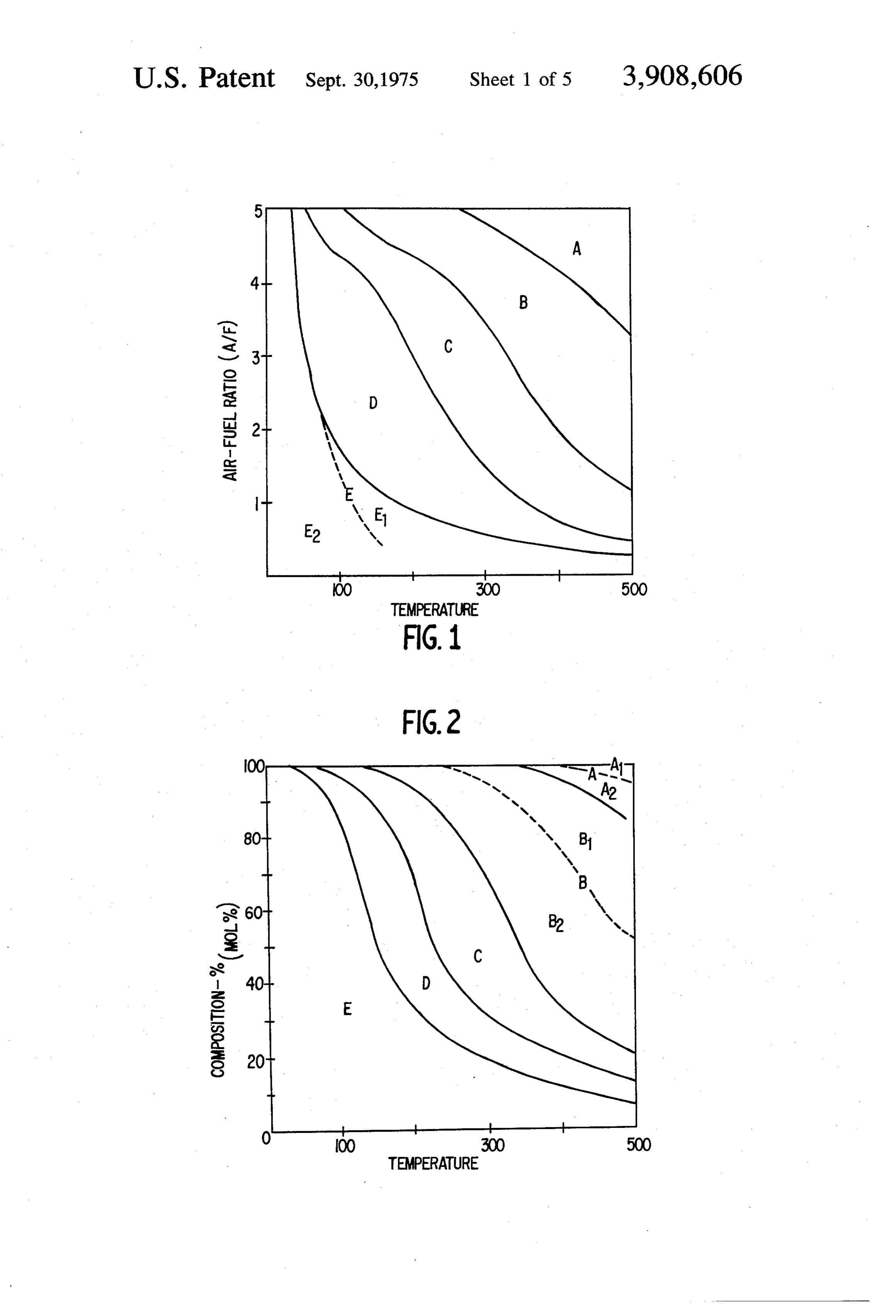
The present invention relates to an internal combus FIG. 1 is a schematic diagram showing the relation tion engine and more particularly to an internal com ship between the mixture ratio of air and hydrocarbon bustion engine which reduces the emission of harmful, fuel and the temperature in a series of decomposition elements in the exhaust gas thereof. and oxidation reactions;
2. Description of the Prior Art FIG. 2 shows the relationship between the decompo Conventional internal combustion engines have not 10 sition and oxidation products of n-hexane and the tem been constructed such that the fuel used can be im perature;
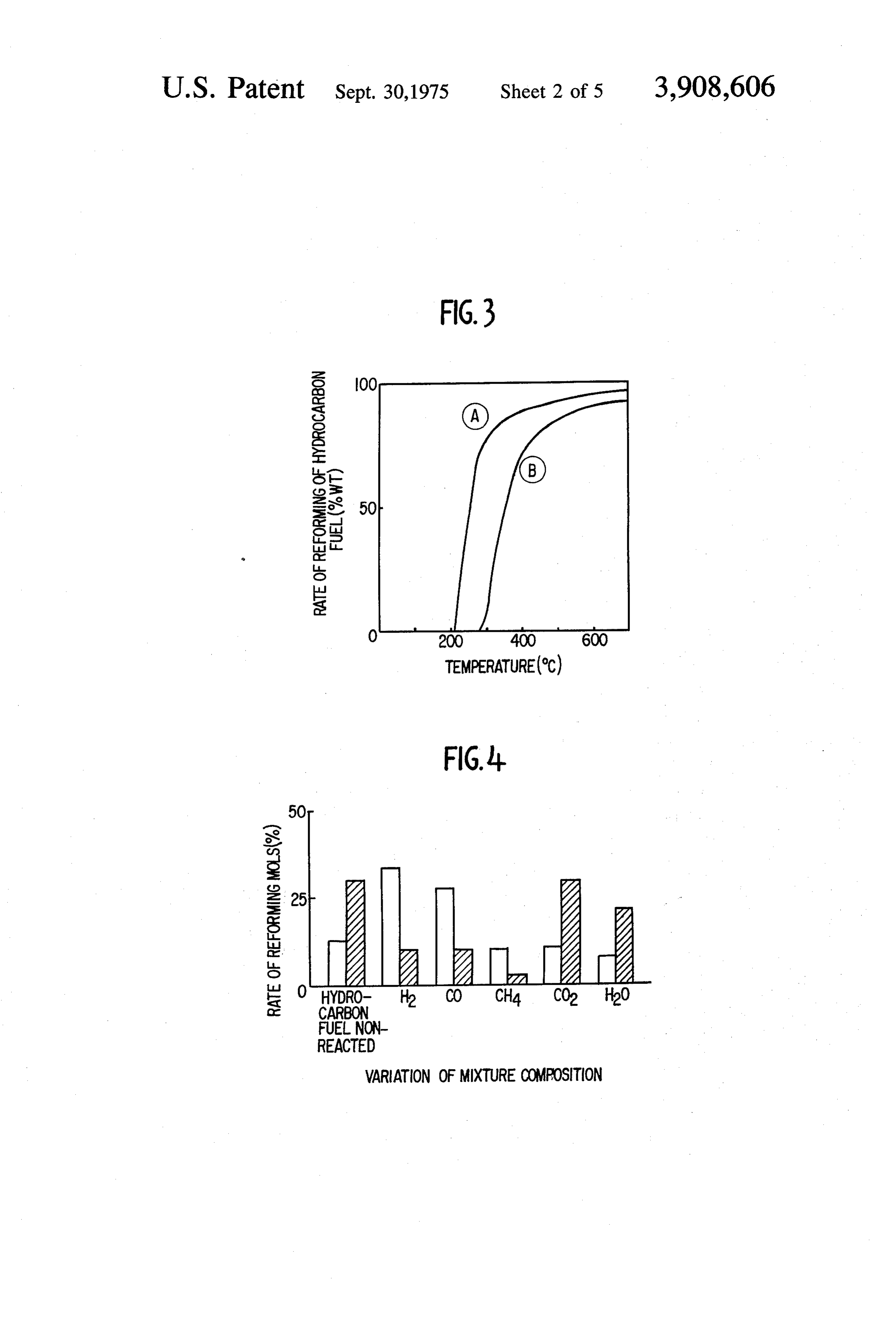
proved before being supplied to the cylinders. With the FIG. 3 shows the relationship between the reforming conventional internal combustion engines in use, re rate of hydrocarbon fuel and the reaction temperature search efforts have been primarily directed to the elimi rise with the effect of a catalyst; nation of harmful elements from the exhaust gas or to 5 FIG. 4 illustrates an example of the variations of mix the perfection of combustion of fuel, but very little at ture compositions of the reaction products of an air tention has been directed to improvement of the fuel to fuel ratio of 3 and a reaction temperature of 400°C; be used. FIG. 5 illustrates curves for the reaction rate in the
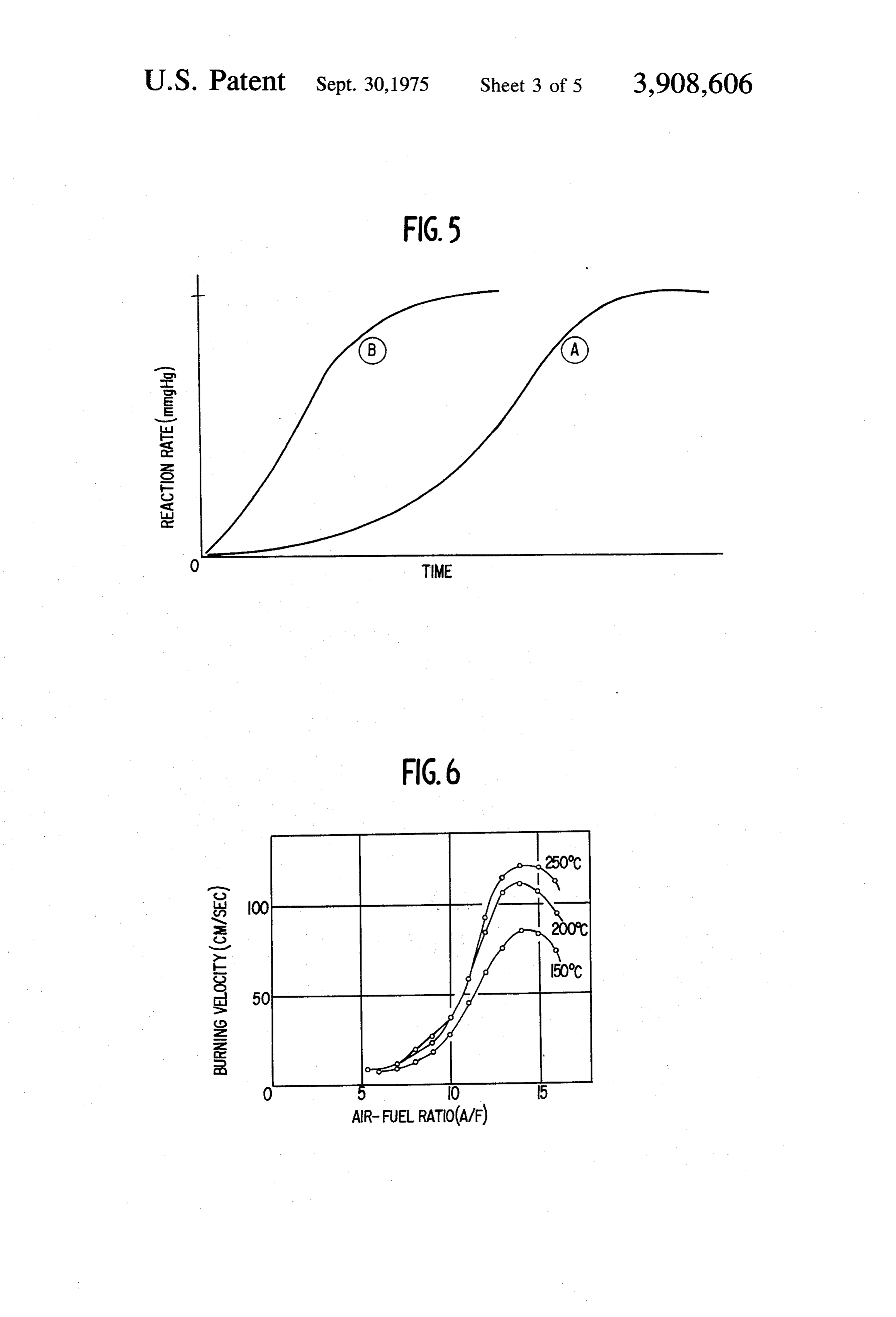
oxidation process of gaseous hydrocarbons;
FIG. 6 shows a burning velocity as to the gases of re
It is accordingly an object of the present invention to formed mixtures of hydrocarbon fuel and air at each provide an internal combustion engine in which effi air-fuel ratio and at the reforming temperatures of cient combustion of the fuel and purification of the ex 150°C, 200°C and 250°C, respectively; haust gas is attained. FIG. 7 is a cross-sectional view of an engine as a pre
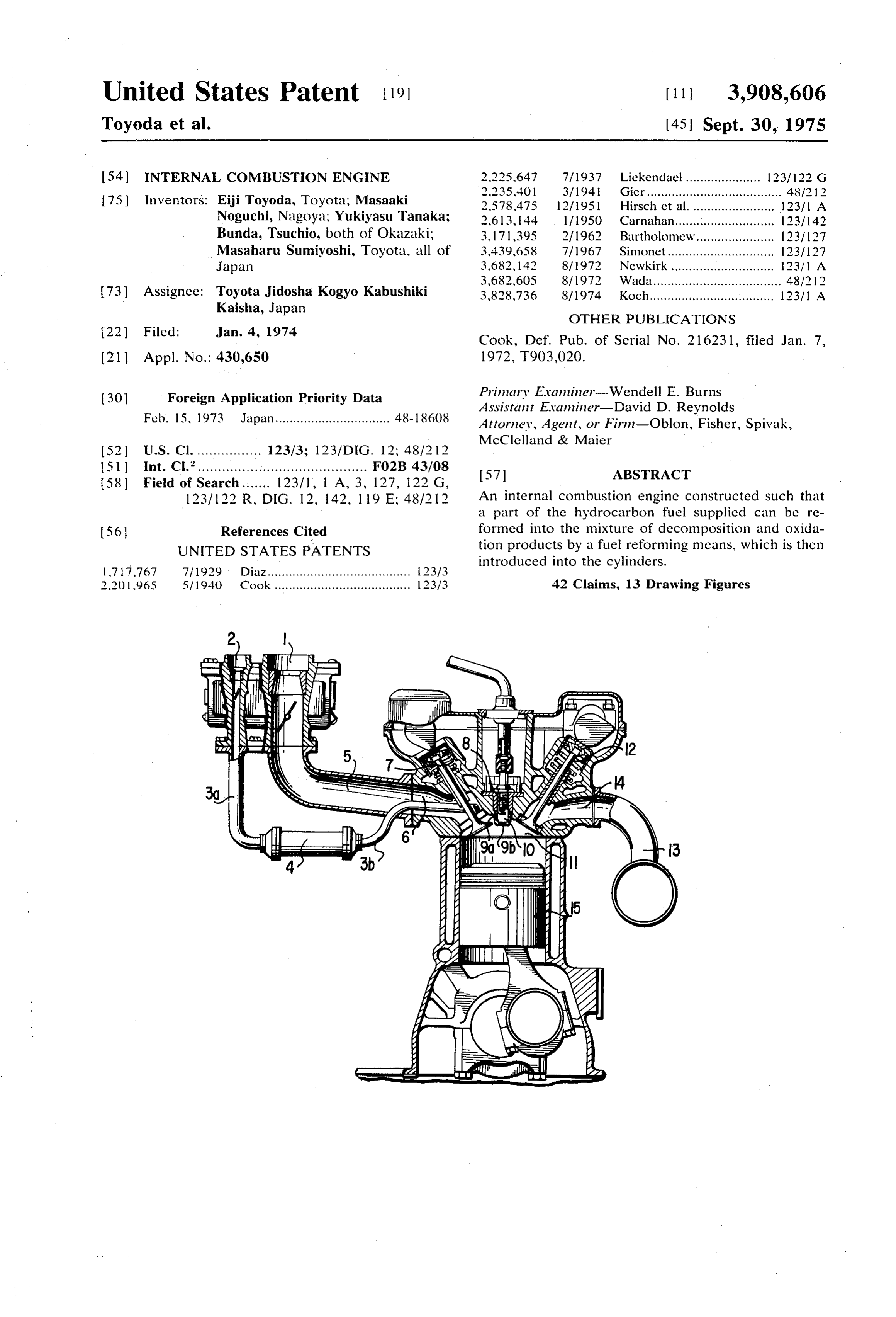
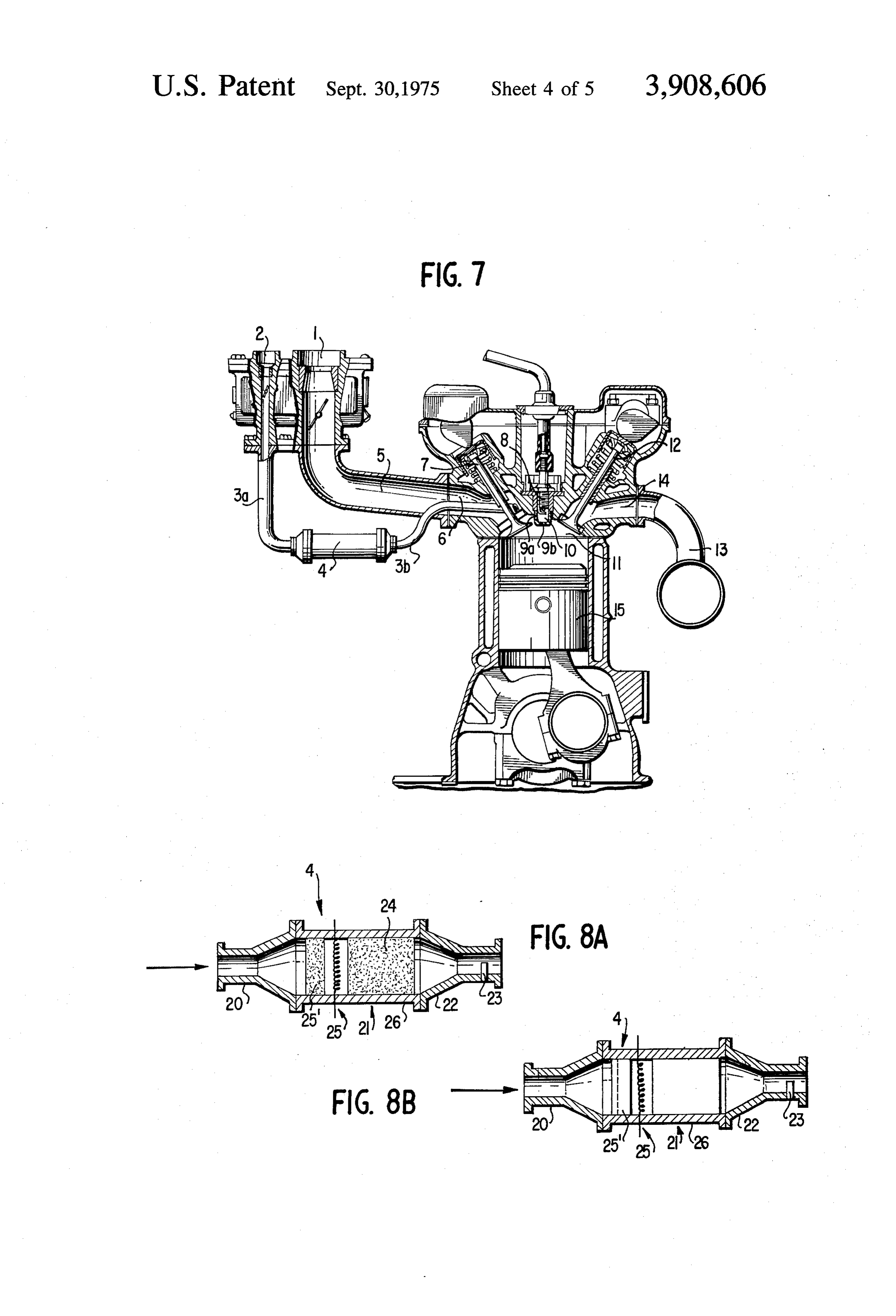
It is still a further object of the present invention to ferred embodiment of the present invention; provide an internal combustion engine which is con FIGS. 8A and 8B respectively show a fuel-reforming structed such that a part of the hydrocarbon fuel is means adopted in the embodiment of the present in treated in the presence of oxygen to obtain a mixture of decomposition and oxidation products including var vention; and
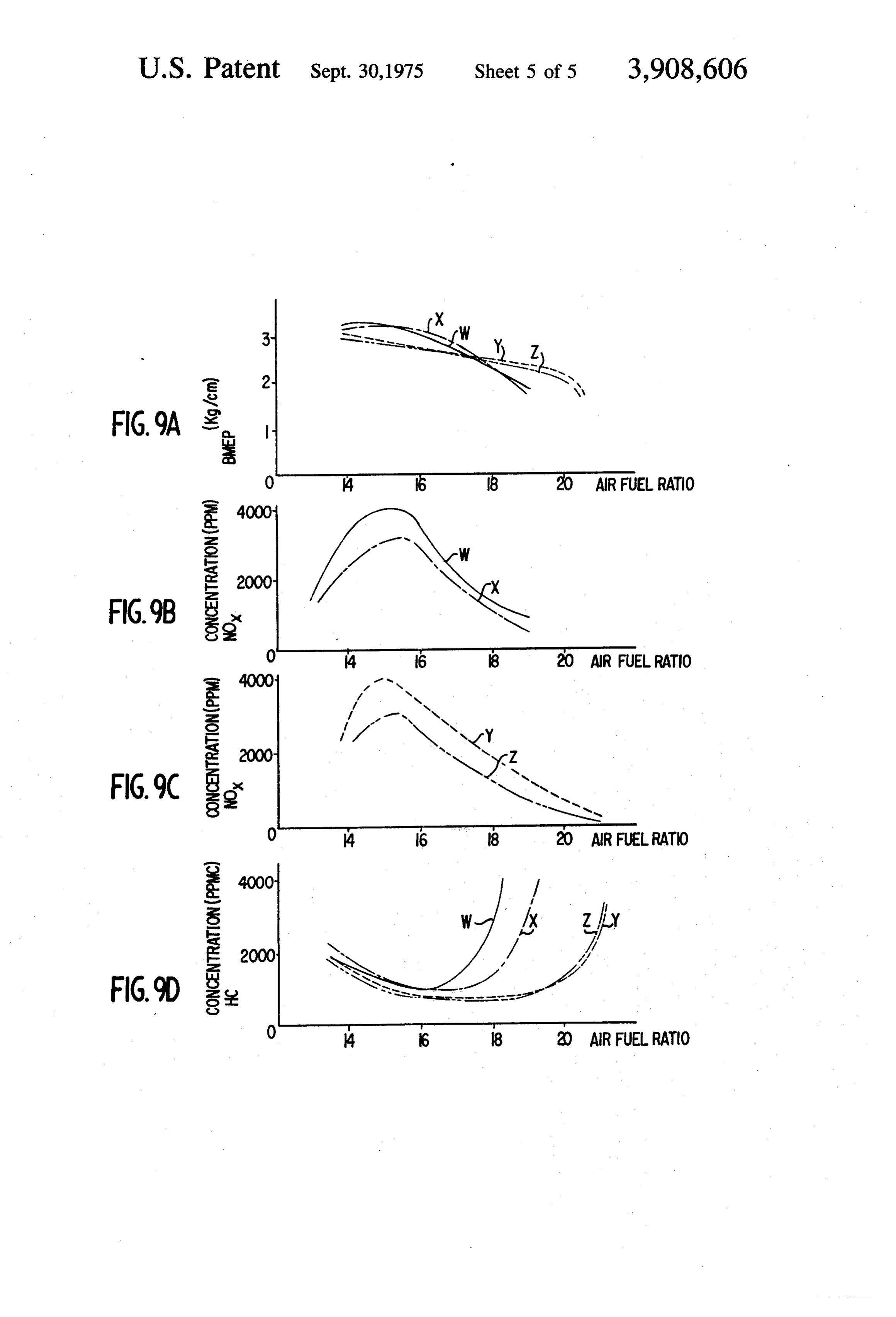
FIG. 9A-D are diagrams showing the relationship be
ious reaction products and wherein this mixture is sup tween the air-fuel ratio and the break mean effective plied to the cylinders. pressure or the emission amount of NOx and HC in the Briefly, in accordance with one embodiment of this case of operating the internal combustion engine with invention, these and other objects are attained by pro the reforming or non-reforming treated fuel. viding an internal combustion engine constructed such that a part of the hydrocarbon fuel supplied can be re 35 DESCRIPTION OF THE PREFERRED formed into the mixture of decomposition and oxida EMBODIMENT tion products by a fuel reforming means, which is then The present invention relates to an internal combus introduced into the cylinders. tion engine wherein a part of the hydrocarbon fuel is The improved mixture of decomposition and oxida treated in the presence of oxygen or air, thereby ob tion products of the present invention includes chemi 40 taining a mixture of decomposition and oxidation prod cal species, such as aldehydes and ketones, lower ali ucts with phatic hydrocarbons with 1-5 carbon atoms; hydrogen; ture is thenvarious compositions, and wherein the mix supplied to the cylinders.
carbon monoxide; carbon dioxide; alkylbenzene deriv atives; organic carboxylic acid, and the like. The feed 45 tures in the presence offuel
When a hydrocarbon is treated at high tempera containing the product mixture in the cylinders influ (or air), the oxidation reaction inamounts excessive general, of oxygen proceeds ences the following:
Firstly, the aldehydes and ketones and their interme substantially perfectly and carbon dioxide and water diate in the process of oxidation are highly effective for areThethe primary products in this region. improvement and control of the combustion process; 50 ventionreformingrefers to treatment proposed in the present in a treatment which takes place under secondly, the components present in the mixture of decomposition and oxidation products such as lower considerably mitigated conditions as compared with aliphatic hydrocarbons produced by chemical bond the above, that is, in the presence of less oxygen and at relatively low temperatures.
rupture, evaporated hydrocarbons of fuel, carbon mon oxide and hydrogen, together with the components 55 cover The conditions for the above reforming treatment mentioned above which exert the first effect, are useful the following ranges: the region where partial ox for increasing the burning velocity and improving the idation of hydrocarbons occurs and production of car combustion process itself, notably for improving the bon monoxide and hydrogen are more pronounced; the ignition and combustion process when they exist in the region of a more mitigated treatment where lower hy vicinity of the ignition source or the flame surface; and 60 drocarbons with 1 to 5 carbon atoms are produced as thirdly, the hydrogen in the mixture of decomposi a result of the chemical bond rupture, oxygen addition tion and oxidation products contributes to reduction products of these lower hydrocarbons, and aldehydes and decomposition of nitrogen oxides generated in the and ketones which are oxygenated compounds pro combustion process, together with carbon monoxide duced by introducing oxygen to hydrocarbon mole and others. 65 cules are produced; and the region of a still more miti gated treatment where a mainly gaseous mixture with
BRIEF DESCRIPTION OF THE DRAWINGS a composition similar to the volatile components of the The objects and features of the invention will become original hydrocarbon fuel is produced.
Page 8
FIG. 1 schematically illustrates the positions of typical curves for reforming at an air-fuel ratio of 3 boundaries of each region as mentioned above con with and without a catalyst, respectively, and FIG. 4 in cerning the ratio of air and hydrocarbon fuel (for in dicates an example of the variation of mixture composi stance, gasoline) and the temperature. In FIG. 1, A, B, tions of products at an air-fuel ratio of 3 and reaction C, D, E, E and E2 represent the reaction regions; A 5 temperature of 400°C, where the white column and di being one of perfect oxidation, B one of partial oxida agonally hatched column indicate each of the compo tion, C one of intermolecular oxidation, D one of ther nents obtained by reforming treatment with and with mal decomposition and E one where no reaction oc out a catalyst, respectively.
curs. In A the major components are CO2, H2O; in B, As these figures show, for both curves (A) and (B) the CO, H2; in C, aldehydes and ketones; in D, lower hy 10 reforming rate of hydrocarbon fuel therefore increases drocarbons with 1 to 5 carbon atoms; in E1, a mixture rapidly with a temperature rise over a range of of gaseous hydrocarbons; and in E2, a mixture of liquid 150-500°C, the starting temperature shown in curve(A) hydrocarbons. is lower than curve (B) the rate shown in curve (A) is The scope of reforming treatments in this invention higher than curve?B) and a mixture of chemical species includes in a series of decomposition and oxidation re 15 which contribute to combustion, i.e., H., CO, CH and actions taking place under the treatment of hydrocar others can be selectively obtained in favor of catalysts. bon fuel in the presence of oxygen, the region of de The mixture of decomposition and oxidation prod composition and oxidation in which hydrocarbons with ucts of the hydrocarbon fuel takes part in the combus 1 to 5 carbon atoms are produced by chemical bond tion mechanism exhibiting the following effects: rupture of fuel hydrocarbons and addition of oxygen to 20 Firstly, the aldehydes and ketones in these products them and as the oxidation products thereof aldehydes of decomposition and oxidation and the intermediate and ketones are formed; the region of partial oxidation products of oxidation thereof are extremely effective in which carbon monoxide and hydrogen are formed; for improvement and control of combustion; and the region of gasification in which fuel hydrocar secondly, the lower aliphatic hydrocarbons produced bons are evaporated. 25 by chemical bond rupture, gasified hydrocarbons, car The basic range of reforming conditions for hydro bon monoxide and hydrogen, together with the prod carbon fuel according to the present invention are a ucts mentioned above which exert the first effect, asso relatively low temperature and low oxygen concentra ciate with increasing the burning velocity and improv tion, i.e., 150 to 500C and a weight ratio of air to fuel 30 ing combustion itself. Particularly, when they are pres hydrocarbon of 1 to 5. Further, the reforming condi ent in the vicinity of the ignition source and the flame tions must be such that a flow rate matching the opera burning surface, the effect is remarkable; and tion of the engine can be assured; with such conditions thirdly, the hydrogen present in the products of de being secured through adequate function and structure composition and oxidation contributes to reduction of the fuel reforming means. One method available for 35 and decomposition of nitrogen oxides generated in the this purpose is to mitigate the reforming conditions combustion process together with carbon monoxide through proper selection of the catalyst which is used and others.
to promote catalytically the oxidation which is the main The first effect which is found particularly significant reaction. In this case, provided that the selection of the is hereinafter elaborated. According to “Combustion catalyst and other important factors such as the tem Flames and Explosions of Gases' by Bernard Lews and perature, the air (oxygen concentration), and the space 40 Guenther von Elbe et al. the flame-propagation speed velocity of reactants over the catalyst bed are proper, and the burning velocity at the interface between flame a mixture of decomposition and oxidation products and combustible medium which affect the traveling re which contribute to improvement of the combustion action zone through the combustible medium are con mechanism in the cylinders can be selectively obtained. sidered to depend on the chain reaction involved by The mixture of decomposition and oxidation prod 5 burning; and the rate of this chain reaction is deter ucts thus yielded in the above-mentioned scope and mined by the concentration of chain carriers developed range of reforming conditions contains: aldehydes and in the process.
ketones, lower aliphatic hydrocarbons with 1 to 5 car In the products of decomposition and oxidation bon atoms, hydrogen, carbon monoxide, carbon diox 50 yielded from the fuel-reforming means, lower hydro ide, alkylbenzene derivatives, organic carboxylic acid; carbons with 1 to 5 carbon atoms which are formed as and, hydrocarbons yet to react, water and the residual the result of chemical bond rupture and aldehydes and components of the air used as the oxidizing agent are ketones which are products of oxidation thereof are contained. clearly detected. Introduced into the cylinders, these FIG. 2 illustrates the formation of a mixture of de 55 oxidation products are subjected in the combustion composition and oxidation products in one example of process to further oxidation as expressed by the for the reforming treatment in which the material is n mula (1), thereby yielding radical-peroxide as an inter hexane and the air-fuel ratio (A/F) is set at 3. in FIG. mediate substance and then OH, H and O radicals are 2, the major products of reaction are: products of per formed to act as chain carriers, thus promoting the fect oxidation in A, H2O in A, CO2 in A2, products of 60 chain reaction of the combustion. partial oxidation in B, H, in B1, CO in B, aldehydes and R-CHOH-O-D R-CO(OOH) - R-COO--OH . . . ketones which are hydrocarbon compounds containing oxygen in C, hydrocarbons with 1-5 carbon atoms (1) which are lower hydrocarbon compounds in D, and hy drocarbons yet to react, i.e., n-hexane in E. 65 Further explanation is to be made in reference to FIG. 3 indicates the relationship between the reform FIG. 5, which illustrates typical kinetic curves for the ing rate of hydrocarbon fuel and reaction temperature oxidation of gaseous hydrocarbons with time, where(a) rise with the effects of a catalyst, where,(A)(B) indicate is a curve showing the pressure rise versus time accom
Page 9
S 6 panying the oxidation process of the hydrocarbon-air in spark plug 8 and communicates via the orifices 9a, mixture and (B) is a curve showing the similar pressure 9b with the combustion chamber 11. The main intake rise versus time when a small fraction of aldehyde is manifold is shown at 5, the exhaust valve at 12, the ex contained. haust manifold at 13, exhaust port at 14 and the piston It is apparent from FIG. 5 that addition of aldehydes, at 15.
which is one of the components contributing to the re FIGS. 8 (A) and (B) respectively show the structure forming of hydrocarbon fuel, strongly accelerates the of the fuel-reforming means according to the present reaction rate and promotes the burning velocity. invention. The fuel-reforming means 4 includes the Namely, the supply of aldehyde with carbonyl radical inlet 20, the reforming part 21 and the outlet 22. The to the cylinders improves the burning velocity on the reforming part 21 includes a cylinder 26, a catalyst bed burning surface. 24 of alumina, platinum or the like, and an electric FIG. 6 indicates the burning velocity with respect to heater 25 connected to a battery (not shown). A back the gases obtained by reforming a mixture of air and fire-preventing element 25' is arranged just before the hydrocarbon fuel at each air-fuel ratio and prereacting electric heater 25 for the purpose of preventing back temperatures. It is clear from FIG. 6 that the burning 15 fire into the 3a side of the suction pipe. velocity of air-hydrocarbon fuel mixture is rapidly pro FIG. 8(A) shows the back-fire-preventing element moted by seeding of the flame surface with chemical 25 consisting of catalysts. The reference numeral 23 species from the reforming treatment at a relatively low indicates a thermometer provided at the outlet 22. temperature. Shown in FIG. 8(B) are the inlet 20, the reforming The present invention provides an internal combus 20 part 21 and the outlet 22, the reforming part being tion engine with various merits which are given by an formed as a cylinder, the reforming part houses the improved mechanism of combustion in which a part of electric heater 25 connected to the battery and does the hydrocarbon fuel supplied to the engine is reform not include a catalyst bed. FIG. 8(B) represents the treated under the above-mentioned conditions and case of reforming a part of the fuel by heating of the then the mixture of decomposition and oxidation prod 25 heater 25.
ucts is distributed to the cylinders. In the embodiment with the above construction of In this case, only a part of hydrocarbon fuel is reform the present invention, the fuel supplied to the auxiliary treated for supply to the engine. This is because a rela carburetor 2 can easily be ignited near the ignition plug tively small amount of the mixture suffices for ensuring and 12 - 38 percent of the total fuel suffices to provide and improving the ignition and combustion in the cylin the mixture of decomposition and oxidation products ders. The reforming treatment of all fuel supplied to the which is necessary for subsequent combustion and con engine would involve various drawbacks such as a de trol. This 12-38 percent of the fuel is adjusted to a rel crease in the volumetric efficiency, a loss of calorific atively rich mixture in the carburetor 2 which comes value inherent in the fuel, difficulty in control of the 35 via the auxiliary suction pipe 3a into reforming means air-fuel ratio and difficulty in treating the fuel at the 4. The rich mixture which has come into the reforming start or stop of the engine. Partial reforming treatment means begins to be reformed through heating by the of the supplied fuel has an advantage of raising the electric heater 25 and the reformation is maintained by compression ratio if necessary, thereby improving the the catalyst bed 24 whose temperature attains the spec rate of fuel consumption by 10 - 15 percent. Also, the 40 ified level until a reformed mixture of decomposition partial reforming treatment of the supplied fuel makes and oxidation products with the above-mentioned com it possible to ignite and burn a lean mixture which will position is obtained. The fuel thus reformed is in the not be done in the conventional engine equipped with suction stroke sent to the trap chamber 10 via the auxil a carburetor; thereby the harmful elements in the ex iary suction pipe 3b which opens in the vicinity of the haust gas can be reduced. Moreover, the reforming intake valve 7 and through the orifice 9a bored in the treated fuel contains lower molecule hydrocarbons and 45 trap chamber 10. As the tip of the auxiliary suction other chemical species produced by decomposition and pipe 3b opens in the direction of the trap chamber 10 oxidation compared to the original hydrocarbon fuel. upstream of the intake valve 7, a considerable portion Therefore, when they exist in the vicinity of the ignition of the mixture of decomposition and oxidation prod source or flame surface, it becomes relatively easy to SO ucts goes into the trap chamber 10 through the orifice burn a light oil which is usually difficult to burn. Thus, 9a.
the engine of the present invention is fit for a wide vari The remaining portion of the mixture flows out to the ety of fuels. top of the combustion chamber 11 and at the end of the The construction, function and effect of a four-cycle compression stroke one part of this portion back flows reciprocating engine as an embodiment of the present 55 into the trap chamber 10 through the orifices 9a, 9b of invention is hereinafter described in reference to the the trap chamber 10. The other part remains near the attached drawings. orifices 9a, 9b at the top of the combustion chamber Referring now to FIG. 7, there is shown a main car 11. Meanwhile, the relatively lean mixture which has buretor 1, an auxiliary carburetor 2 and a fuel been sucked into the main carburetor 1 is in the suction reforming means 4, one end of which communicates 60 stroke supplied to the cylinders via the main intake via an auxiliary suction pipe 3a with the auxiliary car manifold 5 and the intake valve 7. The relatively rich buretor 2 and the other end of which communicates mixture containing the mixture of decomposition and with an auxiliary suction pipe 3b. The auxiliary suction oxidation products which is now present in the trap pipe 3b is installed within the intake port 6 and the tip chamber 10 is then easily ignited by the spark plug 8 thereof is located upstream of the intake valve 7, where 65 and the combustion is started. As the result of combus it opens in the direction of a trap chamber 10 which tion being started in the trap chamber 10, a flame jet captures a part of the blend of decomposition and oxi spurts into the mixture through the orifices 9a, 9b and dation products. The trap chamber 10 includes a built through this flame ignition, the lean mixture which oc
Page 10
cupies the greater part of the combustion chamber 11 Obviously, numerous modifications and variations of and the cylinders is reliably burned. Thus, the lean mix the present invention are possible in light of the above ture as a whole can be burned and the amount of harm teachings. It is therefore to be understood that within ful elements in the exhaust gas can be reduced. In this the scope of the appended claims the invention may be connection, when reforming the fuel, it is further desir practiced otherwise than as specifically described ous to utilize the catalyst reaction. herein.
In the illustrated embodiment of tie present inven What is claimed as new and desired to be secured by tion, an auxiliary suction pipe and a trap chamber are Letters Patent of the United States is: effective means for adopting a partial reforming treat 1. A method for reducing emission of harmful ele ment of the supplied fuel, but the present invention is O ments in the exhaust of an internal combustion engine, not confined to use of such an auxiliary suction pipe comprising the steps of:
and such a trap chamber. introducing a first quantity of fuel and a first quantity The proportion of the part of fuel supplied to the aux of air into a reformer: - iliary carburetor in the above is set at 12 to 38 percent, reforming said first quantity of fuel into a first mix which is found one of the most effective ratios for re 15 ture containing decomposition and oxidation prod ducing the harmful elements in the exhaust gas in the ucts of said first quantity of fuel; present embodiment using the auxiliary suction pipe feeding said first mixture to a combustion chamber of and the trap chamber; and this ratio can vary with an said engine;
internal combustion engine of different construction feeding a second quantity of fuel and a second quan
tity of air to said combustion chamber, wherein
In the case of a rotary piston engine, the above said second quantity of fuel and said second quan mentioned effects will be attained by sucking and hold tity of air have not passed through said reformer; ing the mixture of decomposition and oxidation prod and ucts in a belt fashion along the center line of the width 25 burning said first mixture and said second quantity of of the rotor housing where the spark plug is located and fuel in said combustion chamber. thus the difficulty of combustion in the conventional 2. A method according to claim 1, wherein said first rotary piston engine will be eliminated for better per mixture, said second quantity of fuel and said second formance and exhaust gas. quantity of air are mixed prior to ignition in said com FIGS. 9A-D illustrate examples of improvement ass bustion chamber.
to the performance of the engine and the harmful com 3. A method according to claim 1, wherein said sec ponents emitted therefrom in the case of using the re ond quantity of fuel and said second quantity of air formed fuel. from a lean mixture in said combustion chamber, and For this purpose, the experiments were conducted wherein said first mixture is introduced essentially sep for the engine installed with a trap chamber and for a 35 arately from said lean mixture.
conventional engine using the reformed fuel. 4. A method according to claim 3, wherein said first More specifically, FIGS. 9A-D are diagrams showing comparison of characteristics among the cases of: (W) mixture is introduced adjacent an ignition means in said combustion chamber.
operating the conventional internal combustion engine 5. A method according to claim 3, wherein at least a with the non-reform treated fuel, (X) operating the 40 portion of said first mixture is introduced into a trap conventional internal combustion engine with the re chamber enclosing an ignition plug in said combustion form treated fuel, (Y) operating the internal combus chamber.
tion engine installed with a trap chamber by the non 6. A method according to claim 1, wherein said de reform treated fuel and (Z) operating the internal com bustion engine installed with a trap chamber by the re 45 composition and oxidation products include carbon
form treated fuel.
In more detail, FIG. 9A shows the relationship be 7. A method according to claim 1, wherein said de tween the air-fuel ratio and the break mean effective composition and oxidation products include aldehydes pressure (B.M.E.P.). As is evident from this diagram, and8. ketones.
A method according to claim 1, wherein said de the engines are of little difference in the break mean 50 composition and oxidation products include lower ali effective pressure, i.e., driving torque, regardless of the phatic hydrocarbons having from 1 to 5 carbon atoms. reform treatment of the fuel.
FIGS. 9B-C respectively show the relationship be 9. A method according to claim 1, wherein said first tween the air-fuel and the emission amount of NOx as mixture also includes a vaporized non-reformed fuel. 10. A method according to claim 1, wherein said re to the conventional internal combustion engine and the 55 forming internal combustion engine installed with the trap is carried out in the presence of a catalyst. chamber. From these, it is apparent that the emission 1. A method according to claim 1, wherein the air amount of NOx lowers substantially, when both of the fuel ratio of said first quantity of fuel and said first engines are operated by the reform treated fuel. More quantity of air is between 1 and 5, and wherein said re over, the emission amount of HC, which is given in 60 forming is carried out at temperatures between 150 and 5OOC.
FIG. 9D, indicates that there is little difference be tween the reforming-and the non-reforming fuels. 12. A method according to claim 1, wherein said first However, in the case of a conventional internal com quantity of fuel is 12 to 38 percent by weight of the sum bustion engine, the region generating the maximum of quantities of said first and second quantities of fuel. amount of hydrocarbons shifts to the right-direction in 65 13. A method according to claim 4, wherein said first this figure by employing the reformed fuel, which mixture is fed mainly to the top of said combustion means that the combustible critical range of the air-fuel chamber and wherein said ignition means is located in ratio expanded. said top of said combustion chamber.
Page 11
14. A method according to claim 3, wherein said lean 25. The method of claim 17, wherein said decompo mixture is fed into said combustion chamber through sition and oxidation products include aldehydes and an intake port and said first mixture is fed into said ketones.
combustion chamber through an auxiliary suction con 26. The method of claim 17, wherein said decompo duit which opens upstream of and in the vicinity of an 5 sition and oxidation products include lower aliphatic intake valve disposed in said intake port. hydrocarbons having from 1 to 5 carbon atoms. 15. A method according to claim 5, wherein said trap 27. The method of claim 17, wherein a portion of chamber has at least one aperture, whereby a portion said hydrocarbon fuel introduced into said reforming chamber is vaporized without being reformed and of said first mixture is introduced into said trap cham 10 wherein ber through said aperture to be ignited in said trap into saidsaid vaporized non-reformed fuel is introduced combustion chamber with said reformed fuel.
chamber such that a flame spurts into said lean mixture 28. The method of claim 17, wherein said reforming through said aperture. is conducted in the presence of a catalyst. 16. A method according to claim 1, wherein: 29. The method of claim 17, wherein the air-fuel said first quantity of fuel and said first quantity of air 15 ratio in said reforming chamber is between 1 and 5 and are mixed to form a rich air-fuel mixture in an aux wherein said reforming is conducted at temperatures iliary carburetor prior to introduction into said re between 15 O' and 500°C.
former; 30. The method of claim 17, wherein at least a por said second quantity of fuel and said quantity of air tion of said reformed fuel is fed into a trap chamber in are mixed in a main carburetor to form a lean air said combustion chamber and wherein said reformed fuel mixture prior to being fed to said combustion fuel in said trap chamber is ignited so as to produce a chamber through a main intake manifold and an flame which spurts into the remaining portion of fuel in intake port, said manifold being connected to said said combustion chamber.
main carburetor at one end thereof and to said in 31. An internal combustion engine, comprising: take port at the other end thereof; and 25 a combustion chamber;
said first mixture is fed through an auxiliary intake a piston disposed in said combustion chamber; conduit which is connected to said reformer at one a power take-off mechanism operatively connected end thereof and being open at the other end to said piston and cooperating therewith for pro thereof upstream of and in the vicinity of intake ducing and transmitting power produced in said valve disposed in said intake port. 30 combustion chamber;
17. A method of reducing emission of harmful ele an exhaust system connected to said combustion ments in the exhaust of an internal combustion engine chamber;
having a combustion chamber comprising the steps of: a first supply system connected to said combustion introducing a hydrocarbon fuel and air into a reform 35 chamber for supplying a lean air-fuel mixture ing chamber; thereto;
reforming said fuel so as to produce a reformed fuel means for reforming fuel and air into a first mixture comprising decomposition and oxidation products; comprising decomposition and oxidation products introducing air, said reformed fuel and a non of said fuel, reformed fuel into said combustion chamber 40 a second supply system connected to said means for wherein the predominant amount of the total quan reforming for supplying said fuel and air to said tity of fuel introduced into said combustion cham means for reforming at a rich air-fuel ratio; and ber has not been passed through said reforming an intake system connected at one end thereof to said chamber.
means for reforming and operatively connected at the other end thereof to said combustion chamber 18. The method of claim 17, wherein said fuel intro 45 for supplying said first mixture to said combustion duced into said reforming chamber is reformed at tem chamber.
peratures of 150 to 500°C. 32. An engine according to claim 31, further com 19. The method of claim 17, wherein said non prising ignition means disposed in said combustion reformed fuel is mixed with said reformed fuel prior to chamber, and wherein said other end of said intake sys ignition in said combustion chamber. 50 tem is disposed such that a considerable portion of said 20. The method of claim 19, wherein said second first mixture is fed to the vicinity of said ignition means. mentioned air is mixed with said non-reformed fuel 33. An engine according to claim 31, wherein said prior to being mixed with said reformed fuel. second supply system is adjusted to keep said rich air 21. The method of claim 17, wherein at least a por fuel ratio between l and 5.
tion of said reformed fuel is introduced essentially Sep 55 34. An engine according to claim 31, wherein said arately from said non-reformed fuel into said combus means for reforming is adapted to carry out said re tion chamber. forming at temperatures between 150 and 500°C. 22. The method of claim 17, wherein at least a por 35. An engine according to claim 31, wherein said tion of said reformed fuel is introduced adjacent an ig 60 first supply system comprises a first carburetor and said nition means in said combustion chamber. second supply system comprises a second carburetor 23. The method of claim 17, wherein the quantity of connected to said means for reforming. fuel introduced to said reformer is 12 to 38 percent of 36. An engine according to claim 34, wherein said the total quantity of fuel introduced into said combus combustion chamber is defined by a cylinder and a cyl tion chamber. 65 inder head and wherein said piston is a reciprocating 24. The method of claim 17, wherein said decompo piston.
sition and oxidation products include carbon monoxide 37. An engine according to claim 35, wherrein said and hydrogen. first supply system further comprises an intake mani
Page 12
fold connected to said first carburetor, an intake port prising a fuel tank connected to said first and second connected to said intake manifold and communicating carburetors, and wherein said fuel is gasoline and said with said combustion chamber, and wherein an intake fuel is 12 to 38 percent by weight of the total fuel intro valve is disposed in said intake port and said intake sys duced into said combustion chamber. tem comprises a conduit connected to said means for 40. An engine according to claim 31, wherein said reforming at one end thereof, the other end of said con means for reforming includes a catalyst thereby said re duit opening into said intake port upstream of and in forming being conducted in the presence of said cata the vicinity of said intake valve. lyst.
38. An engine according to claim 32, further com 41. An engine according to claim 32, wherein said prising a trap chamber disposed in said combustion O means for reforming includes a catalyst thereby said re chamber enclosing said ignition means and having at forming being conducted in the presence of said cata least one aperture defined therein, said trap chamber lyst.
being capable of trapping said first mixture which en 42. An engine according to claim 31, wherein said ters into said trap chamber through said aperture means for reforming comprises a heating element dis whereby said first mixture is ignited in said trap cham 15 posed therein for heating said fuel, and a backfire trap ber which produces a flame to spurt through said aper disposed therein for preventing backfiring into said sec ture. ond supply system.
39. An engine according to claim 34, further com
Provenance
- Collection
- Cited prior art
- Original PDF
- patentimages.storage.googleapis.com →
- Filed
- 1974-01-04
- Pages
- 12
- Method
- pdftotext (the PDF's own text layer) + pdftoppm 300dpi page scans
- Source
- Google Patents bibliographic record
- Granted
- 1975-09-30
- Inventors
- Eiji Toyoda; Masaaki Noguchi; Yukiyasu Tanaka; Tsuchio Bunda; Masaharu Sumiyoshi; Toyota Motor Corp
- Transcribed from
- patentimages.storage.googleapis.com →