patent · US4203426
Solar energy converter carousel mounted rack
20 May 1980
Page 1 — bibliographic record
United States Patent (19) (11) 4,203,426 Matlock et al. 45) May 20, 1980 (54) SOLAR ENERGY CONVERTER CAROUSEL 4,030,890 6/1977 Diggs ................................... 126/27 MOUNTED RACK 4,109,638 8/1978 Matlock et al. ...................... 126/271 4,148,301 4/1979 Cluff..................................... 126/271 76 Inventors: William C. Matlock; Patricia Primary Examiner-James C. Yeung Matlock, both of 510 S. 52nd St., Attorney, Agent, or Firm-Warren F. B. Lindsley
21) Appl. No.: 933,097 57 ABSTRACT 22) Filed: Aug. 11, 1978 A solar energy collector and converter, carousel mounted rack comprising a plurality of elongated re (51) Int. C.’................................................. F24J 3/02 flectors mounted for arcuate movement on a platform 52) U.S. C. ..................................... 126/425; 126/438 and mounted for further arcuate movement each (58) Field of Search ............... 126/270,271, 425, 438, around a heating tube arranged in the linear focus of the 126/439; 237/1 A; 350/283, 282,288, 299 reflectors, the carousel and reflectors each being linked (56) References Cited to tracking mechanisms which cause the reflectors to be trained toward the location of the sun so that they re
3,924,604 12/1975 Anderson ............................. 126/270 4,000,734 1/1977 Matlock et al. ...................... 126/271 5 Claims, 10 Drawing Figures
Page 2
Drawing sheet — no readable text.
Page 3
Drawing sheet — no readable text.
Page 4
SOLAR ENERGY CONVERTER CAROUSEL
relative position to the source of heat will remain con
Stant.
MOUNTED RACK While such prior art inventions do suggest workable approaches for the realization of the important objec
BACKGROUND OF THE INVENTION 5 tives involved, the particular implementations de The rapid expansion of the world's population cou scribed in the prior art has general fallen short of what pled with the accelerated technological development of is required in a low-cost and practical system. large sectors of the world has produced a dramatic SUMMARY OF THE INVENTION increase in the demand for energy in all forms including fuels and electricity for heating, lighting, transporta In accordance with the invention claimed, an im tion, and manufacturing processes. The construction of which proved solar energy collector and converter is provided hydroelectric facilities and the development of fossil is compact and inexpensive by virtue of its uniquely designed reflectors and its sun-tracking mech fuel resources has continued at a rapid rate, but it be anism.
comes increasingly evident for a number of reasons that these efforts are inadequate to keep pace with the de 15 an Itimproved is, therefore, one object of this invention to provide solar energy collector carousel.
mands of the growing population.
Another
In the face of these growing demands and limited pact and inexpensive object of this invention is to provide a com resources, there is one source of energy which is readily mounted solar energy collecting rack on a movable supporting available to every country in the world in virtually ing maximum energy collection throughout platform for achiev unlimited quantities. This virtually untapped source is virtue of its effective yet inexpensive solarthetracking day by solar energy.
The interest in this almost boundless resource and in mechanism and converter moving mechanisms. its development and harnessing for use in homes and improved A further object of this invention is to provide an factories is rising as other resources dwindle. Its desir 25 on rack mounted solar energy collector mounted a rotating ability is further enhanced by the fact that solar energy adjusting the direction platform for vertically and rotationally may be converted to practical use without the hazard of to track the position of the of the reflectors as appropriate environmental contamination. sun throughout the daylight hours.
PRIOR ART Further objects and advantages of the invention will 30 become apparent as the following description proceeds
Until recently, the development of solar energy col and the features of novelty which characterize this lectors has been associated for the most part with pro invention will be pointed out with particularity in the grams involving military and space applications while only limited attention has been given to broad consumer claimstion.
annexed to and forming a part of this specifica use. As a result, there is a great potential for improve 35 ments in existing collection devices that will result in BRIEF DESCRIPTION OF THE DRAWING reduced manufacturing costs and improved thermal The present invention may be more readily described efficiencies.
by reference to the accompanying drawing in which:
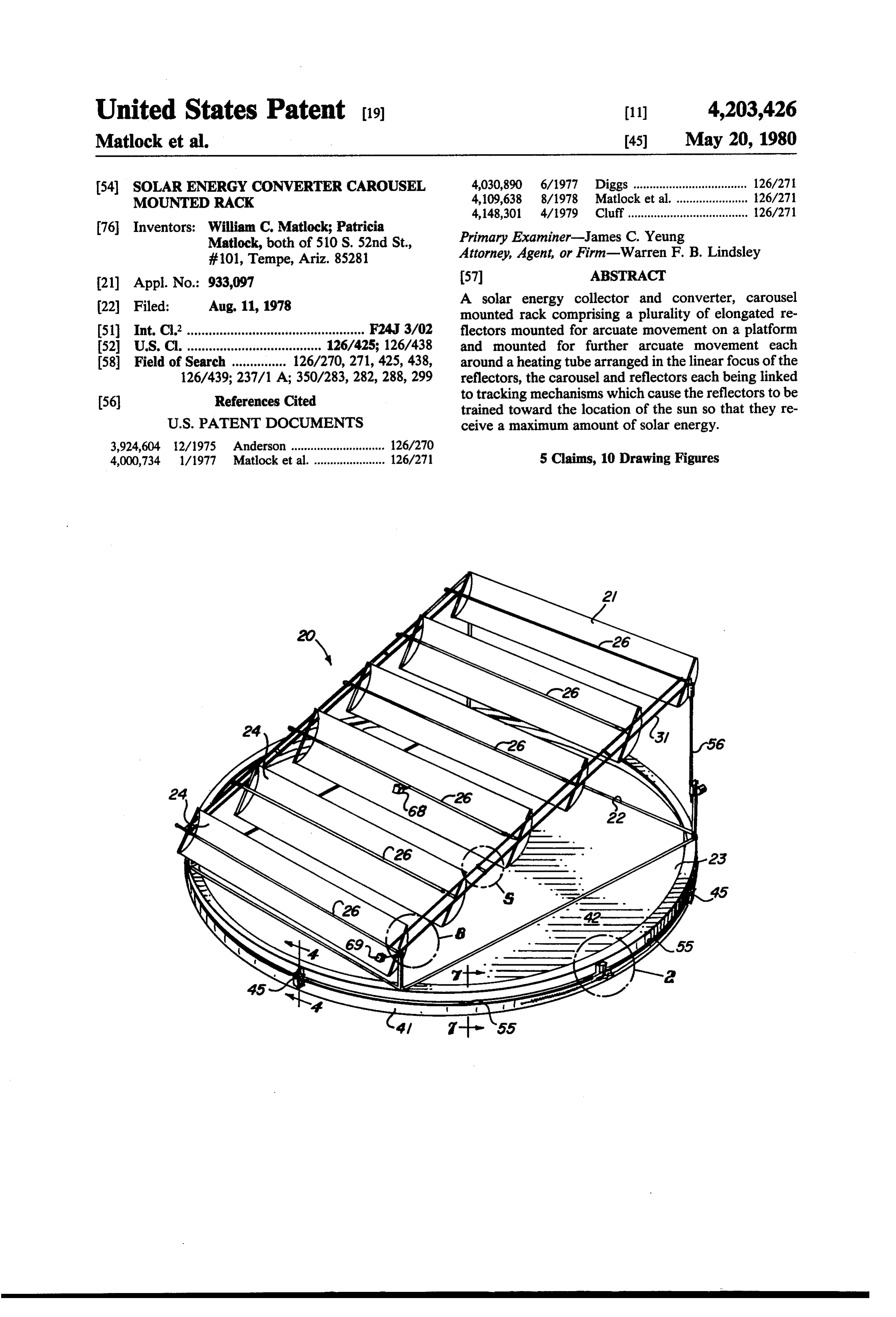
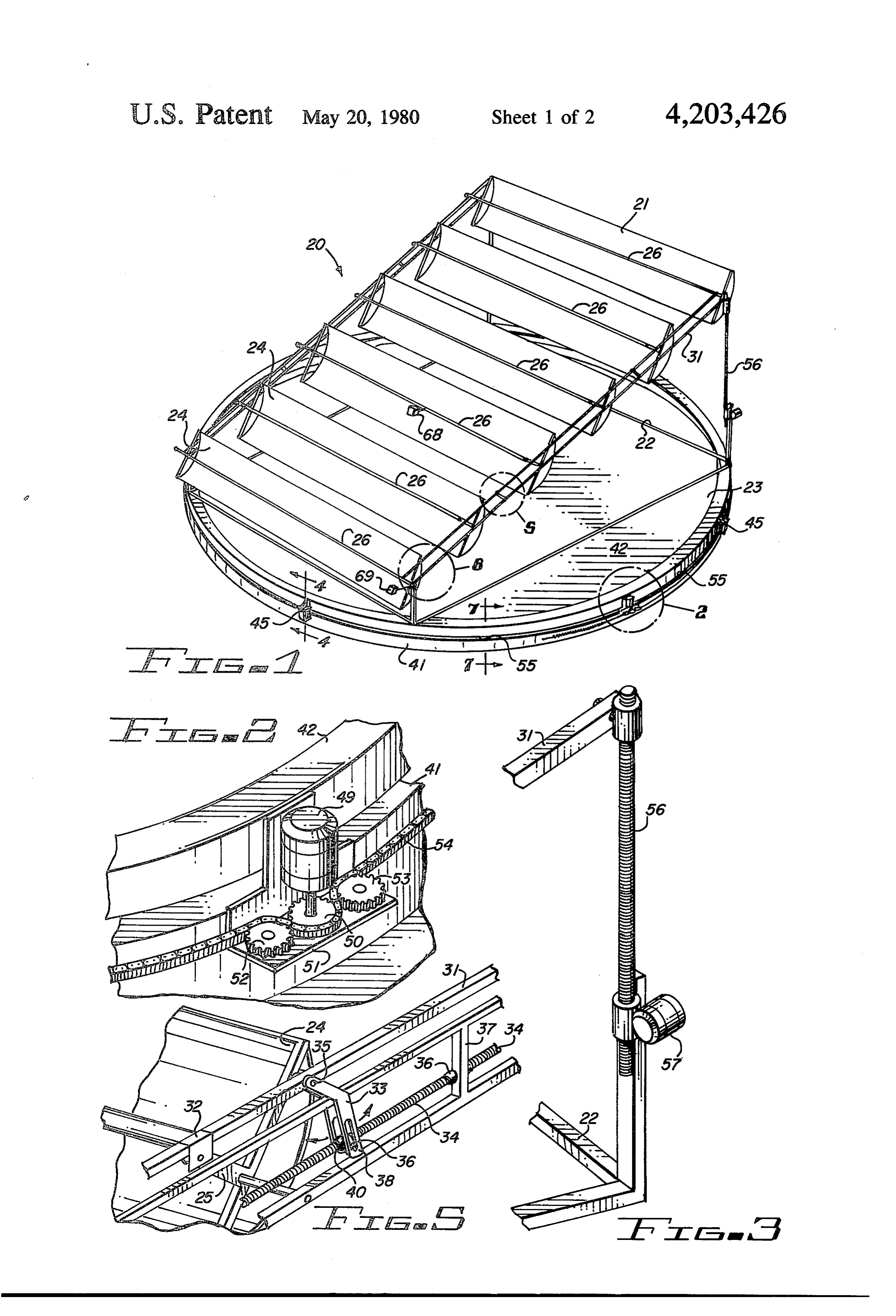
One such device known as a flat plate collector is FIG. 1 is a perspective view of a solar energy rack made of metal and glass with one or more layers of glass 40 mounted collector positioned on an arcuate movable laid over a blackened metal plate. Air spaces are pro carousel employing means for tracking the position of vided between the layers of glass and air or water passes the sun;
through tubes under the metal plate to remove the col FIG. 2 is a close-up view of a portion of the carousel lected thermal energy. The layers of glass in coopera moving tion with the blackened metal plate act as a heat trap, 45 FIG. 3means of FIG. 1 identified as area 2; is an enlarged partial view of FIG. 1 showing letting in the sun's rays but keeping most of the heat one of the rack elevating means;
from escaping again.
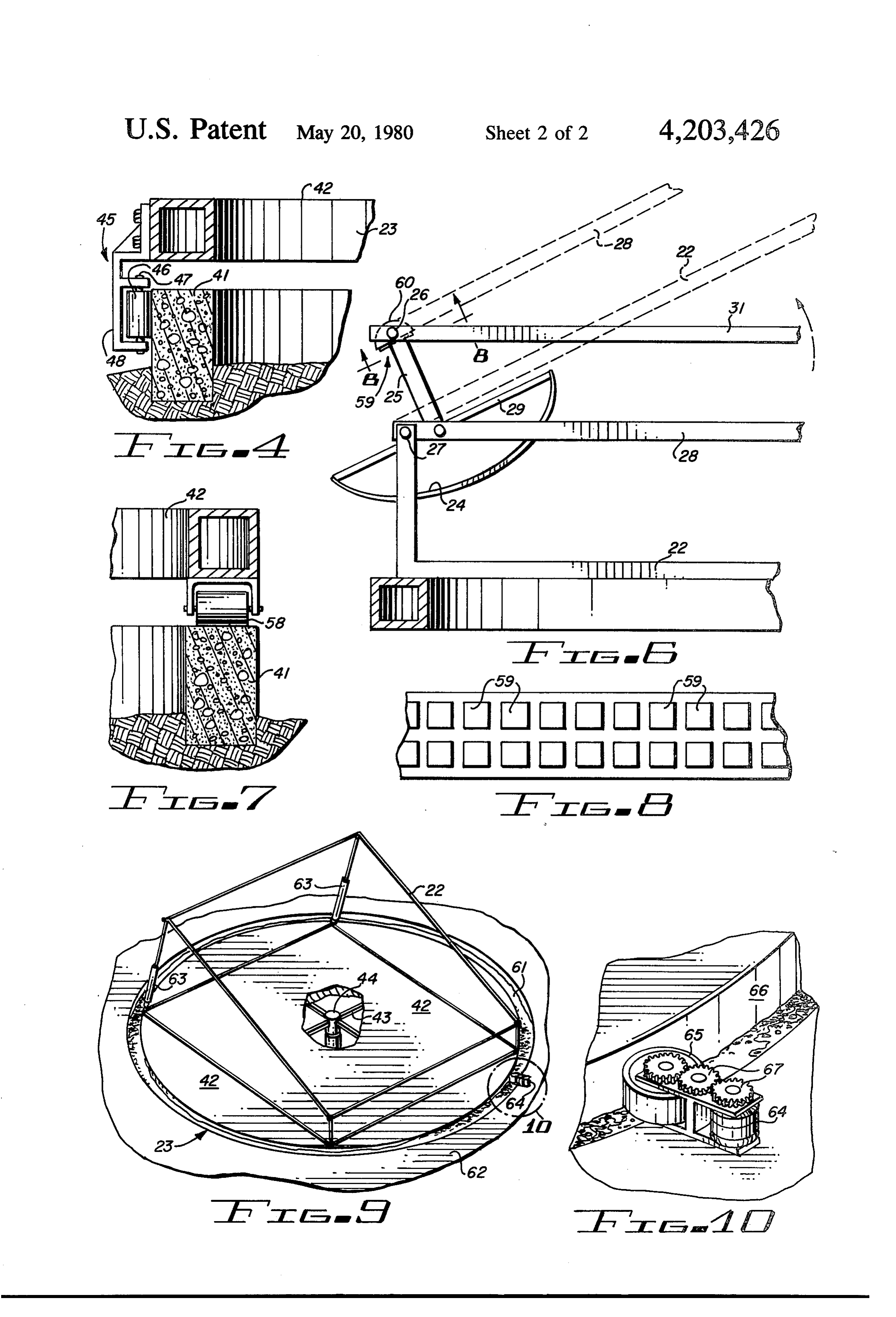
A major disadvantage of the flat plate collector is that lineFIG. 4-4;
4 is a cross-sectional view of FIG. 1 taken along it must be very large in order to collect sufficient en FIG. 5 is a close-up view of the portion of FIG. 1 ergy, the large size resulting in part from the fact that 50 identified as area 5;
except for brief periods during the day its surface is not FIG. 6 is a close-up view of FIG. 1 identified as area perpendicular to the rays of the sun. 6;
A second disadvantage is that the flat plate collector FIG. 7 is a cross-sectional view of FIG. taken along does nor permit the concentration of solar energy at a line 7-7;
localized point as needed for the most effective heating 55 FIG. 8 is a cross-sectional view of FIG. 6 taken along of the water and the conversion of water to steam such the line 8-8 showing an arrangement of photovoltaic as required in certain solar-to-electrical conversion pro cells;
CeSSS.
FIG. 9 is a diagrammatic view of a modification of
Parabolic reflectors have been utilized in the past the structure shown in FIG. 1 and showing the carousel along with sun-tracking mechanisms is connection with rotating means; and various schemes for the collection, conversion and utili FIG. 10 is a close-up view of FIG. 9 identified as area zation of solar energy. Such equipment is described in 0.
At best, the prior art heat exchangers have been ex DESCRIPTION OF THE PREFERRED tremely efficient even to the point where it is necessary 65 EMBODIMENT to incorporate thereinto an elaborate system of gears Referring more particularly to the drawing by char and racks or other means to shift or otherwise change acters of reference, FIGS. 1-6 disclose a solar energy the positions of the exchange or collector unit so that its collection and conversion apparatus 20 utilizing an
Page 5
array 21 of pivoting reflectors rotatably supported on a such as the carousel type structure 23 which rides on a rack 22, the total structure being supported on and concrete ring 41, shown in FIGS. 1, 2 and 4. movable with a carousel type structure 23. The carousel type structure comprises a platform 42 The array 21, a portion of which is shown in FIGS. 1, as shown in FIGS. 1, 4 and 9 employing a flat circular 5 and 6, comprises a multiplicity of trough shaped re 5 member 42 supported by radial members 43 arranged flectors 24 each pivotally mounted at both ends to rack like spokes of a wheel extending outwardly from a hub. 22. An arm 25 extending perpendicularly from each end The platform 42 may be fabricated from any suitable of each reflector 24 provides a support for a solar en material.
ergy collector pipe 26 which runs parallel with the O A number of roller or wheels assemblies 45 are at length of each reflector 24 coincident with its focal 1 tached to the underside of platform 42 and positioned point so that the reflected rays of the sun are concen for alignment with the concrete ring 41 shown in FIGS. trated on pipe 26. 1 and 4. Each wheel assemble 45, as shown more clearly The pivotal mounting of reflectors 24 on the rack 22, in FIG. 4, comprises, for example, a rubber tire roller 46 as shown in FIGS. 1, 5 and 6, is accomplished by means with an axle 47 supported by an inverted U-shaped of pivot pins 27 which pass through the top horizontal 5 bracket 48. The bracket 48 is welded or bolted to plat members 28 of the rack and through the ends of the form 42. Each wheel assembly 45 is oriented such that reflector frames 29 at the base of the support arms 25 as its of axle 47 is aligned with the adjacent radical member shown. Parallel rows of reflectors 24 are coupled to 43 platform 42 so that as platform 42 is rotated about gether by the parallel collector pipes 26 and by trans 20 its center hub 44 the platform follows smoothly along verse coupler bars 31 which are placed at intervals the flat topped concrete ring 41.
along the lengths of the rows of reflectors. The coupler form The mechanical drive system for the rotation of plat bars 31 are pivotally attached to each of the collector lowspeed 42 on ring 41, as shown in FIG. 2, comprises a pipes 26 by means of U-shaped brackets 32. By virtue of mounted tomotor 49 with a drive sprocket 50 directly the motor shaft, a bracket 51 which carries the coupling thus afforded by pipes 26 and bars 31 25 two idler sprockets 52 and 53 and a roller chain 54. reflectors 23 are caused to rotate in unison as the cou pler bars 31 are moved horizontally. Chain 54, as shown in FIG. 2, is of the type com
The drive mechanism for the provision of such hori an example employed in chain-and-sprocket combinations, zontal motion of the coupler bars includes a rocker arm . of which is the ordinary bicycle chain. Bracket 33 and a jackscrew 34 actuated by a suitable motor 3O part being utilized 51 has an L-shaped cross-section, the upper means (not shown). Reference is made in copending and the perpendicular to mount motor 49 to platform 42 application Ser. No. 784,581, now U.S. Pat. No. mount the idler sprockets lower portion being utilized to 4,109,638 for more details of this type of structure. 52 and 53. As shown in F.G. 2, motor 49 is mounted with its
The rocker arm 33 comprises two identical arms, shaft directed vertically downward so that the drive each fashioned from flat metal stock in the general 35 sprocket 50 lies in a horizontal plane. Idler sprockets 52 shape of a boomerang. The two arms are placed on and 53 have opposite sides of the rack 22 and are each pivotally zontal lower their axles secured vertically to the hori attached to bars 31 by means of a pivot pin 34. The one on each side of of sections the bracket 51 and are positioned drive sprocket 50 coplanar lower portions or arms 33 have longitudinal slots 36 therewith.
traversing most of their lengths and function in a well Chain 54 may be coupled by means of the two springs known manner obvious from the drawing. in the manner shown and described in copending appli Jackscrew 34 is aligned parallel with coupler bar 31 cation and it passes horizontally through free rotation bearings 41, eachSer. No. 784,581, U.S. Pat. No. 4,109,638 to ring end of the chain being attached to a first end of 37 installed in the centers of vertical support members one of the springs and the other end of each of the 38 of rack 22. Jackscrew 34 also passes between the 45 springs being attached to a steel ring which is anchored lower slotted portions of arms 33 to which it is coupled to the vertical outer surface of concrete ring 41. When by means of pins 39 which extend through slots 36 and attached in this manner, chain 54 extends horizontally are welded to a nut 40 which is positioned between the along approximately 240 of the periphery of ring 41. arms 33 and is threadedly engaged with jackscrew 34 so The vertical position of chain 54 which is just below the that as jackscrew 34 is rotated, nut 46 moves by virtue top surface of ring 41, and in line with the sprockets 51, of the engagement of slots 33 by pins 39. A pivoting 52 and 53, may be held at a number of points by means motion of arm 33 is thus effected which in turn effects of guides 55 which are secured to the surface of ring 41. the pivotal motion of reflector 24 about its pivot pin 27. In the complete assembly as shown in F.G. 1, rack 22 Jackscrew 34 may have at one end a wheel gear (not is shown as being supportable in a number of various shown) which engages a screw (shown in application 55 positions laterally of the flat surface of platform 42 by Ser. No. 784,581) in the manner of a worm gear so that threaded rods 56 each of which may be movable in the rotational drive of the screw by a motor produces a unison by one or more screw motors 57. By this mecha corresponding rotation of jackscrew 34. nism, the elevation of the reflectors of their array for The boomerang configuration of arm 33 has utility in relatively small units, i.e. six by ten foot arrays and the affording a slight tilt to the direction of the reflectors in like, may be set according to the latitude of the country the center of its pivotal range at which point a vertical in which it is mounted. For larger units, the threaded orientation of the lower part of arm 33 is most desirable. rods may be replaced with stationary bracings. The vertical orientation, of course, permits equal travel The nearly 240 degrees of rotation thus afforded is of jackscrew 34 in both directions, and the tilt of the adequate to permit array 21 to track the daily path of upper arm corresponds to the average elevation of the 65 the sun across the horizon from sunrise to sunset, and S. the simultaneous control of the elevation of the reflec The rotational tracking capability of system 20 is tors as described earlier in connection with the opera provided by mounting array 21 on a rotating platform tion of the tracking motor for rotating the reflectors
Page 6
permitting a complete and total tracking capability in accomplished by such simple mechanisms thus far de accordance with a primary object of this invention. scribed, requiring only slight and intermittent attention The fluid flow through pipes 26 may follow the sys by the senser without the use of elaborate clockwork or tems described in U.S. Pat. No. 4,000,734 or copending costly mechanisms such as are ordinarily used to focus application Ser. No. 784,581, U.S. Pat. No. 4,109,638 sun rays in astronomical instruments or solar engines. and such systems are incorporated herein by reference Reference is made to U.S. Pat. No. 4,000,734 for thereto. more detail of this focusing means and of the particular FIG. 7 illustrates a further modification of the struc structural details of the light sensor 68. ture shown in FIGS. 1-6 wherein rollers 58 mounted on The disclosed unique arrangement of the azimuth and the bottom surface of platform 42 are arranged to roll 10 altitude tracking of the reflectors is made possible over the top of the surface of ring 41. through the ease of azimuth tracking by the floating FIGS. 6 and 8 illustrate that a plurality of photovol solar collector.
taic cells 59 may be mounted either on the surface of A light sensor 69, shown in FIG. 1 is provided for pipe 26 facing the reflectors 24 or on the shield 60 that purpose. This sensor senses the suns rays and acti which extends along and surrounds at least a part of 15 pipes 26. Shields 60 are provided for restricting heat vates motor 49 for operation in one of two directions radiation from pipes 26. The use of photovoltaic cells 59 the sun's raysorandreverse) (i.e. forward rotates depending on the position of the platform accordingly.
converts solar rays directly into electrical energy in the With the exception of the control circuits which well known manner.
FIGS. 9 and 10 illustrate a further modification of the 20 control the tracking motor 49 and the low speed motor mounting of platform 42 of the carousel type structure solar 64 which rotates platform 42, a complete and effective 23 wherein platform 42 is mounted on water 61 within with the energy system has been described in accordance a confined pool 62. In this instance the threaded rod 56 stated objects of the invention. and screw motor 57 may be replaced by telescoping have Although but a few embodiments of the invention hydraulic or spring biased member 63. 25 been illustrated and described, it will be apparent The platform 42 is rotated by a suitable motor 64 to those skilled in the art that various changes and modi mounted on either the platform or pool side wall but fications may be made therein without departing from shown in FIGS. 9 and 10 as being pool mounted. This the spirit of the invention or from the scope of the ap pended claims.
motor drives a rubber wheel or tire 65 which friction ally engages the peripheral sides 66 of platform 42 for 30 What 1. An is claimed is:
exchange means comprising:
arcuate movement thereof through suitable reduction a rack, gears 67.
One of the basic problems inherent in maximizing the said rack being mounted on a substantially horizontal efficiency of any solar collector is that of tracking the platform having an arcuate configuration, sun. This is particularly true of focusing collectors. This 35 said platform being positioned for rotatable move problem of tracking the sun is greatly reduced, how ment through an arcuate path, ever, when the collectors are mounted on a floating at least a pair of juxtapositioned reflectors mounted platform as disclosed herein. Only a small amount of on said rack in a parallel arrangement, force is needed whether the raft or platform is floated in each of said reflectors comprises a trough having a a confined pool or on open water. 40 parabolic reflecting surface, The orientation of the reflecting troughs shown in means for pivotally mounting each of said reflectors FIG, 1 preferably lie in a parallel series arrangement in a parallel arrangement on said rack, forming a planar configuration, whose plane is at right a fluid bearing tube extending longitudinally of each angles to the plane of the meridian and preferably, of said reflectors on said rack and approximately though not necessarily, parallel to the earth's axis. The 45 disposed with the axis of a portion of said tube in longer axes of the reflecting troughs are approximately the focal zone of an associated reflector. horizontal, and at right angles to the plane of the merid a first electric means for moving said reflectors on ian. The reflecting troughs are rotatable about the axes said rack in unison through a similar arc partially of the portions of the fluid flow line pipe 26 of the around the portion of the tube associated with each troughs and the several troughs are connected by a link 50 of the reflectors for maintaining said reflectors whereby all such reflecting troughs of a series may be with the axis of their curvature approximately in a rotated simultaneously through an angle of 60, more or plane containing the sun's center, less. The screw shown or equivalent means, is adapted a second electric means mounted on said support for for this purpose. This linkage is so adjusted that the sensing the position of the sun for moving said reflecting troughs are oriented similarly with respect to 55 platform to orient and maintain said rack and re the sun at all times, whatever be the angle of setting by flectors with their axes of curvature of their reflec the linkage. A light senser 68 is provided to sense the tive surfaces approximately in a plane containing position of the sun and energize the motor for moving the sun's center.
the reflectors about a common axis if not properly ori said second electric means comprising an electric ented to timely align the reflecting troughs toward the motor for driving said platform sequentially back S. and forth around an arcuate track, By these means all the reflector elements may be said second electric means sensing the position of the properly oriented continually so that the axes of their sun and tracking the sun in an azimuth mode, parabolic cross-sectional curves shall all lie in planes whereby the reflection of the sun's rays are concen including the center of the sun. Under these circum 65 trated by said reflectors in a line image along said stances the rays of the sun will continually focus upon portions of said tubes, and the heater tubes independently of the altitude of the sun means for selectively varying the angular position of above the horizon. In such a manner the orientation is said rack to said platform.
Page 7
2. The heat exchange means set forth in claim 1 said indexing means comprises an electric motor and wherein: a sprocket driven by said motor the teeth of which said second electric means for sensing the position of are intermeshed with said chain for movement the sun comprises a drive means mounted around at thereof, least a part of the periphery of said platform, and 4. The improved heat exchange means set forth in claim 3 in further combination with:
indexing means for causing said drive means to move means connected to said motor for reversing the said platform through an arcuate path depending direction of rotation thereof. on the position of the sun. 5. The exchange means set forth in claim 1 wherein: 3. The heat exchange means set forth in claim 2 10 said portion of said fluid bearing tube extends outside wherein: of the periphery of the associated reflector. said drive means comprises a link chain, and
Provenance
- Collection
- Cited prior art
- Original PDF
- patentimages.storage.googleapis.com →
- Filed
- 1978-08-11
- Pages
- 7
- Method
- pdftotext (the PDF's own text layer) + pdftoppm 300dpi page scans
- Source
- Google Patents bibliographic record
- Granted
- 1980-05-20
- Inventors
- William C. Matlock; Patricia Matlock
- Transcribed from
- patentimages.storage.googleapis.com →