patent · US3925235
Production of luminescence
9 December 1975
Page 1 — bibliographic record
United States Patent (19) (1) 3,925,235 Lee (45) Dec. 9, 1975
54 PRODUCTION OF LUMNESCENCE
(75) Inventor: Vin-Jang Lee, Columbia, Mo. Primary Examiner-Stephen J. Lechert, Jr. Attorney, Agent, or Firm-Koenig, Senniger, Powers 73) Assignee: The Curators of the University of and Leavitt
Missouri, Columbia, Mo.
22 Filed: Oct. 30, 1972 57 ABSTRACT A method and apparatus for continuous production of (21) Appl. No.: 302,359 luminescence. A steady state heterogeneous charge transfer chemical reaction is carried out on the sur 52 U.S. Cl................ 252/188.3 CL; 252/301.4 R: face of a solid state catalyst such as an oxide semicon 252/301.4 F 252/30.6 F ductor, at temperatures substantially below the tem perature of incandescence of the catalytic material.
5l Int. Cl.’............................................ C09K 3100 Chemical energy is directly converted to light energy 58) Field of Search............ 252/188.3 R, 188.3 CL, to provide continuous luminescence, which may be 252/301.4 R, 301.4 F, 301.6 F used at a position spaced from the solid state catalyst region where the luminescence is produced, e.g., for 56) References Cited lasing, process monitoring, characterization of the ac UNITED STATES PATENTS tivity and active sites of a catalyst, etc. 3,493.889 2f197O Henkel ..................... 252, 1883 CL 3 Clains, 2 Drawing Figures
Page 2
Drawing sheet — no readable text.
Page 3
Drawing sheet — no readable text.
Page 4
steady state heterogeneous exothermic charge transfer
PRODUCTION OF LUMNESCENCE chemical reaction on the surface of a Solid state cata
BACKGROUND OF THE INVENTION
lyst at temperatures substantially below the natural ra diation temperature, or temperature of incandescence,
The present invention relates to providing a continu 5 of the catalyst material. Chemical energy is converted ous source of luminescence by a direct conversion of directly into light energy. It is to be understood that by chemical energy to light energy, and more particularly the term light energy as used herein, is meant radiant to methods and apparatus for producing such lumines energy not limited solely to visible light. This lumines cence by charge transfer chemical reactions on the sur 10 cence is utilized at a position spaced from the Solid face of solid state catalysts. state catalyst region where the luminescence is pro Luminescence has been generated in several ways, duced.
such as by electroluminescence and chemical lumines GENERAL DESCRIPTION OF THE INVENTION cence or chemiluminescence. In the former, light emis sion results from the conversion of electric energy into 15 Typical exothermic chemical reactions which are radiant energy, by the combination of electrons and useful in the practice of this invention include the oxi holes in semiconductors. The mechanisms of the elec dation of CO and H, and the decomposition of NaO. tronic transition are either direct interband transition Exemplary solid state catalysts which may be used are or indirect via trapping centers with energy levels in the NiO, ZnO, TiO, Tho, CdC), CuO, MgO and GaAs, energy gap of the semiconductor in accordance with which will be noted, include both semiconductors and the known art of producing visible light from semicon 20 insulators.
ductors as described, for example, in Science, Vol. 159, The heterogeneous exothermic charge transfer reac page 1419 (1968). Luminescence in a solid, especially tions employed in the practice of this invention may be in the bulk in contrast to the interface regions of a p-n described or depicted by two exemplary general mech junction, can also be generated by electrons and holes 25 anisms. The first mechanism may be depicted by the which are localized at nearest neighbor donor-acceptor following exemplary steps and involves the injection of centers, as described, for example, in Physics Today, electrons and holes into the conduction and valence February, 1968, page 43. In chemiluminescence light bands of semiconducting catalysts:
emission is a result of the direct conversion of the A -- (S.C.) = A + p (Valence band) ( ) chemical energy into radiant energy by electronic tran 30 D + (S.C.) = D* + n (Conduction band)
sition from a higher energy state to a lower energy state n - p =hw (4) in atoms and for molecules all in a homogeneous phase.
Transient luminescence generated by the adsorption of where A and D denote respectively any acceptor and gases or vapors on solids has also been observed, as re donor species (molecules, atoms or ions); p represents viewed in, for example, Zietschrift fur Anorganische holes in the valence band of the semiconductor (repre und Allgemeine Chemie, Band 377, page 113 (1970). sented by S.C.); n represents electrons in the conduc In addition to the many uses and applications of such tion band of the same semiconductor; and hu and huv' luminescence as light sources, both electro- and chemi represents respectively the photons emitted during the luminescence have been lased, i.e., the luminescence being amplified by stimulated emission of the radiation, 40 electron-hole the ionic recombination in the semiconductor and reaction on the surface of the catalyst.
the energy "pump' for the former including an exter Thus, from the above described mechanism, it is evi nal d.c. power source, while in the latter the energy dent that the luminescence "pump' is one or a series of chemical reactions involv (1) - (4) involves injectionproduced of via the reactions electrons and of holes.
ing intermolecular energy transfer. In the electrically However, this injection differs markedly from that uti pumped laser, e.g., the well known injection laser 45 lized in producing electroluminescence and/or laser which is constituted by a forward biased p-n junction laser, the light energy output may be modulated by an where the holes and electrons are the result of connect electric field, but the electric energy which is the en ing negative and positive electrodes to an external elec trical power supply and not due to the action of chemi ergy source must be provided by an external power cal agent or reactants A and D. supply. The above-noted chemical laser has the advan SO Light emission is a result of steps (3) and (4). The tage of direct conversion of chemical to light energy light emitted from (3) has the quantum energy of but is not susceptible to modulation by an electric field.
SUMMARY OF THE INVENTION
Among the several objects of this invention is the provision of apparatus and methods for continuously 55 producing luminescence by the direct conversion of Where EA, E are the filled energy levels of the accep chemical into light energy; the provision of such meth tors and donors, e is the electric charge, e is the dielec ods and apparatus which may be utilized for industrial tric constant at the surface and r is the distance be process monitoring and for analytical purposes for de tween the A and D* adions. The light emitted from tecting active sites on solid state catalysts; and such 60 step (4) satisfies the relationship hus Eg, where Eg is methods and apparatus for continuously producting lu the energy gap of the semiconducting catalyst, and h is minescence which may be adapted for use in lasers Planck's constant.
which may be modulated and do not require the use of Another luminescence mechanism is by the following external electrical power supplies for energy pumping, steps.
Other objects and features will be in part apparent and 65 A -- S - S -- A
in part pointed out hereinafter. A -- D = AD - hy' (7) Briefly, and in accordance with this invention, lumi S -- S = S -- S - hy (8) nescence is continuously produced by carrying out a
Page 5
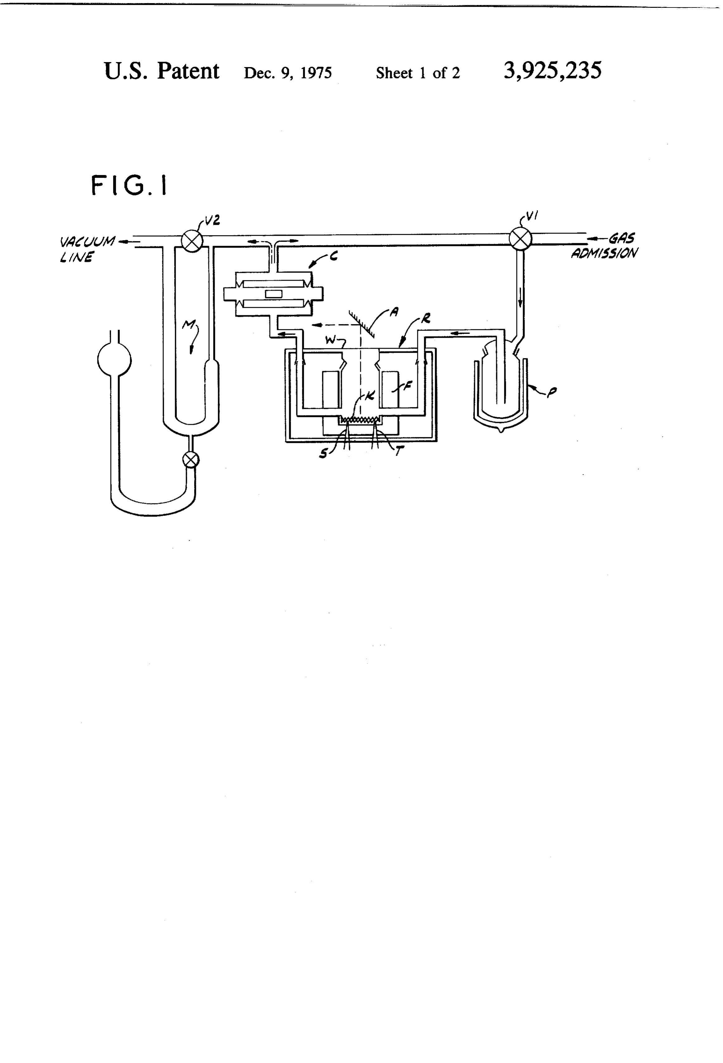
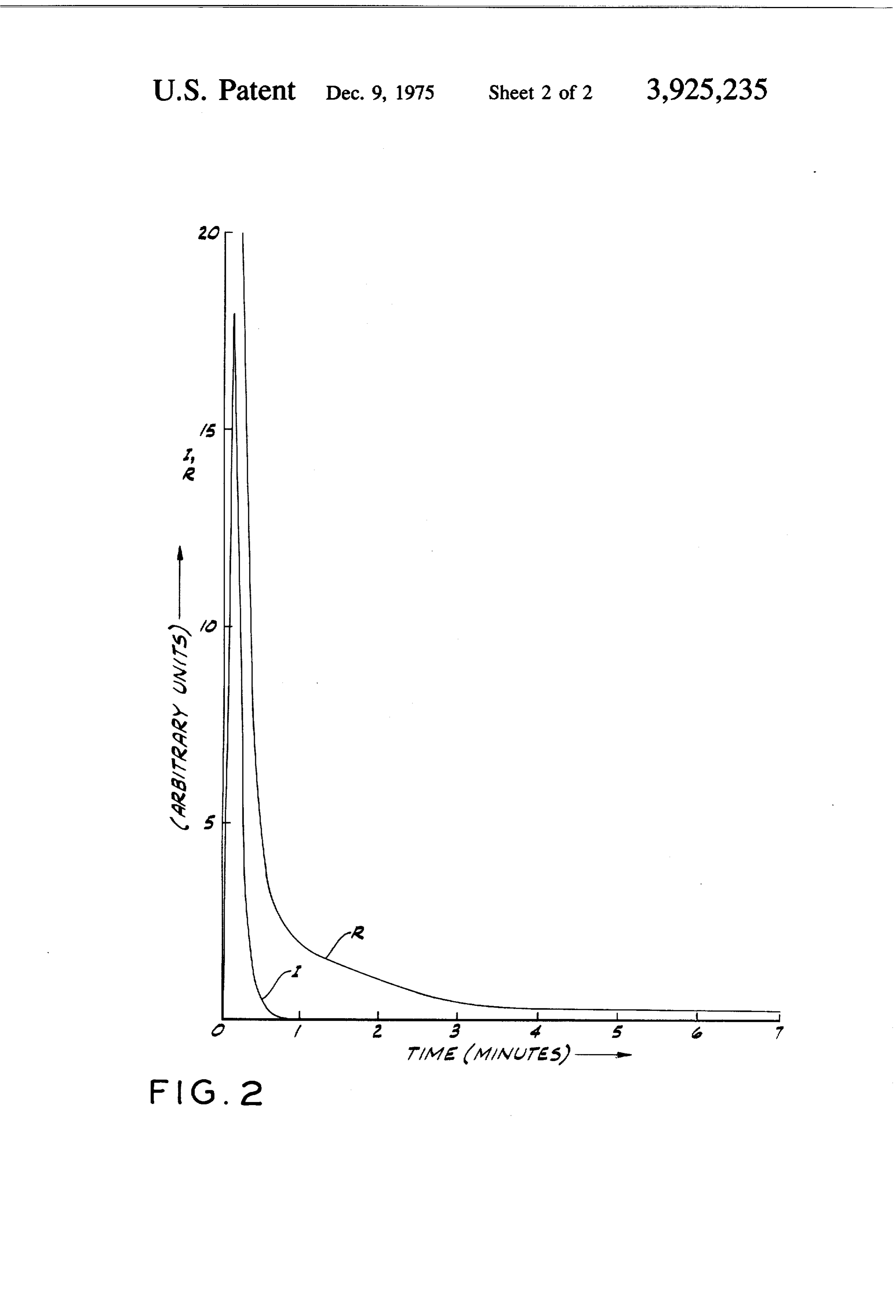
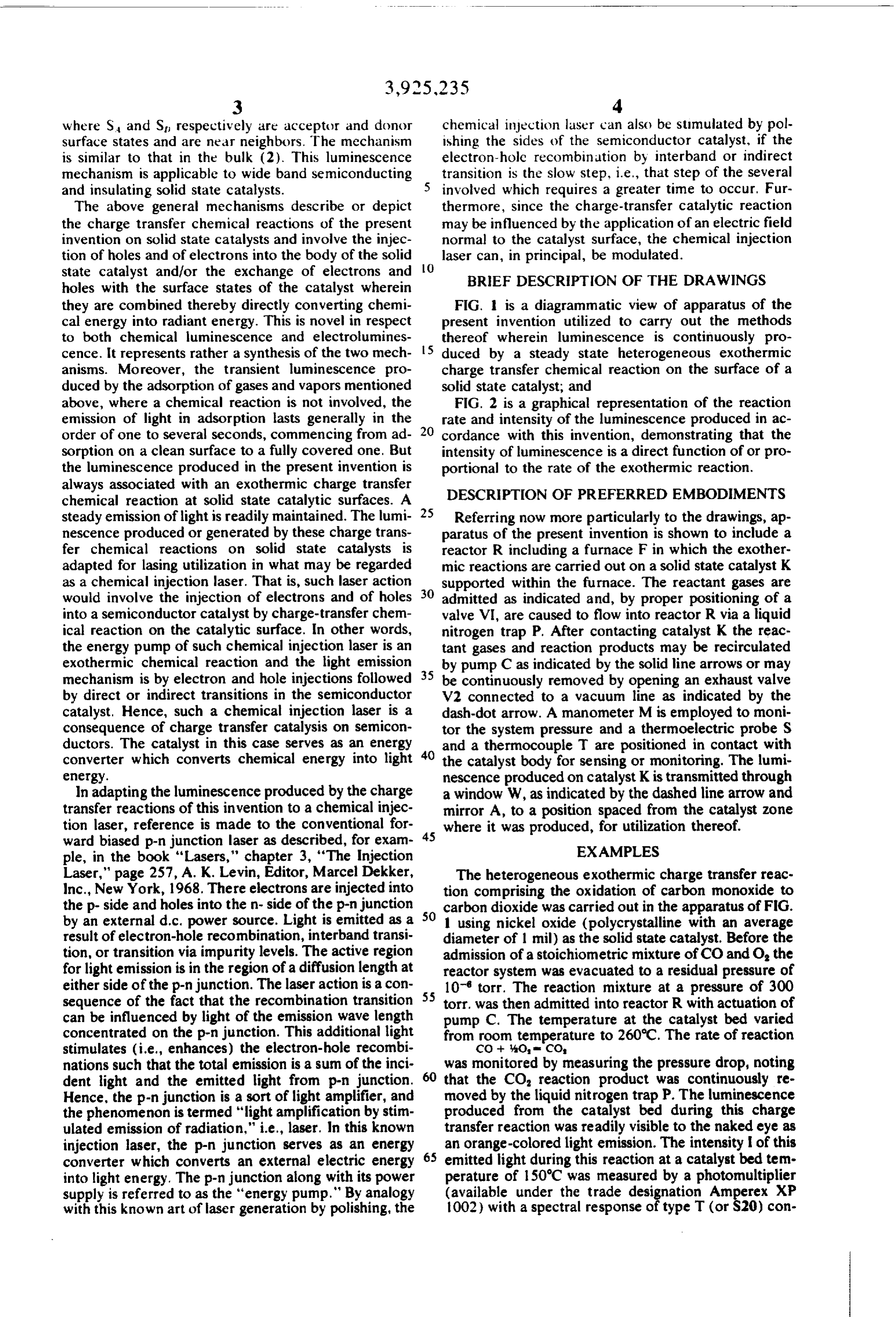
where S and St respectively are acceptor and donor chemical injection laser can also be stimulated by pol surface states and are near neighbors. The mechanism ishing the sides of the semiconductor catalyst, if the is similar to that in the bulk (2). This luminescence electron-hole recombination by interband or indirect mechanism is applicable to wide band semiconducting 5 transition is the slow step, i.e., that step of the several and insulating solid state catalysts. involved which requires a greater time to occur. Fur The above general mechanisms describe or depict thermore, since the charge-transfer catalytic reaction the charge transfer chemical reactions of the present may be influenced by the application of an electric field invention on solid state catalysts and involve the injec normal to the catalyst surface, the chemical injection tion of holes and of electrons into the body of the solid 10 laser can, in principal, be modulated. state catalyst and/or the exchange of electrons and BRIEF DESCRIPTION OF THE DRAWINGS holes with the surface states of the catalyst wherein they are combined thereby directly converting chemi FIG. 1 is a diagrammatic view of apparatus of the cal energy into radiant energy. This is novel in respect present invention utilized to carry out the methods to both chemical luminescence and electrolumines thereof wherein luminescence is continuously pro cence. It represents rather a synthesis of the two mech 5 duced by a steady state heterogeneous exothermic anisms. Moreover, the transient luminescence pro charge transfer chemical reaction on the surface of a duced by the adsorption of gases and vapors mentioned solid state catalyst; and above, where a chemical reaction is not involved, the FIG. 2 is a graphical representation of the reaction emission of light in adsorption lasts generally in the rate and intensity of the luminescence produced in ac order of one to several seconds, commencing from ad 20 cordance with this invention, demonstrating that the sorption on a clean surface to a fully covered one. But intensity of luminescence is a direct function of or pro the luminescence produced in the present invention is portional to the rate of the exothermic reaction. always associated with an exothermic charge transfer chemical reaction at solid state catalytic surfaces. A 25 DESCRIPTION OF PREFERRED EMBODIMENTS steady emission of light is readily maintained. The lumi Referring now more particularly to the drawings, ap nescence produced or generated by these charge trans paratus of the present invention is shown to include a fer chemical reactions on solid state catalysts is reactor R including a furnace F in which the exother adapted for lasing utilization in what may be regarded mic reactions are carried out on a solid state catalyst K as a chemical injection laser. That is, such laser action supported within the furnace. The reactant gases are would involve the injection of electrons and of holes 30 admitted as indicated and, by proper positioning of a into a semiconductor catalyst by charge-transfer chem valve VI, are caused to flow into reactor R via a liquid ical reaction on the catalytic surface. In other words, nitrogen trap P. After contacting catalyst K the reac the energy pump of such chemical injection laser is an tant gases and reaction products may be recirculated exothermic chemical reaction and the light emission by pump C as indicated by the solid line arrows or may mechanism is by electron and hole injections followed 35 be continuously removed by opening an exhaust valve by direct or indirect transitions in the semiconductor V2 connected to a vacuum line as indicated by the catalyst, Hence, such a chemical injection laser is a dash-dot arrow. A manometer M is employed to moni consequence of charge transfer catalysis on semicon tor the system pressure and a thermoelectric probe S ductors. The catalyst in this case serves as an energy 40 and a thermocouple T are positioned in contact with converter which converts chemical energy into light the catalyst body for sensing or monitoring. The lumi energy. nescence produced on catalyst K is transmitted through ln adapting the luminescence produced by the charge a window W, as indicated by the dashed line arrow and transfer reactions of this invention to a chemical injec mirror A, to a position spaced from the catalyst zone tion laser, reference is made to the conventional for 45 where it was produced, for utilization thereof. ward biased p-n junction laser as described, for exam EXAMPLES ple, in the book "Lasers," chapter 3, "The Injection
Laser," page 257, A. K. Levin, Editor, Marcel Dekker, The heterogeneous exothermic charge transfer reac Inc., New York, 1968. There electrons are injected into tion comprising the oxidation of carbon monoxide to the p-side and holes into the n-side of the p-n junction SO carbon dioxide was carried out in the apparatus of FIG. by an external d.c. power source. Light is emitted as a 1 using nickel oxide (polycrystalline with an average result of electron-hole recombination, interband transi diameter of 1 mil) as the solid state catalyst. Before the tion, or transition via impurity levels. The active region admission of a stoichiometric mixture of CO and O, the for light emission is in the region of a diffusion length at reactor system was evacuated to a residual pressure of either side of the p-n junction. The laser action is a con 10 torr. The reaction mixture at a pressure of 300 sequence of the fact that the recombination transition 55 torr. was then admitted into reactor R with actuation of can be influenced by light of the emission wave length pump C. The temperature at the catalyst bed varied concentrated on the p-n junction. This additional light from room temperature to 260C. The rate of reaction stimulates (i.e., enhances) the electron-hole recombi CO + 40, a CO nations such that the total emission is a sum of the inci was monitored by measuring the pressure drop, noting dent light and the emitted light from p-n junction. 60 that the CO, reaction product was continuously re Hence, the p-n junction is a sort of light amplifier, and moved by the liquid nitrogen trap P. The luminescence the phenomenon is termed "light amplification by stim produced from the catalyst bed during this charge ulated emission of radiation," i.e., laser. In this known transfer reaction was readily visible to the naked eye as injection laser, the p-n junction serves as an energy 65 an orange-colored light emission. The intensity of this converter which converts an external electric energy emitted light during this reaction at a catalyst bed tem into light energy. The p-n junction along with its power perature of 150°C was measured by a photomultiplier supply is referred to as the "energy pump." By analogy (available under the trade designation Amperex XP with this known art of laser generation by polishing, the 1002) with a spectral response of type T (or S20) con
Page 6
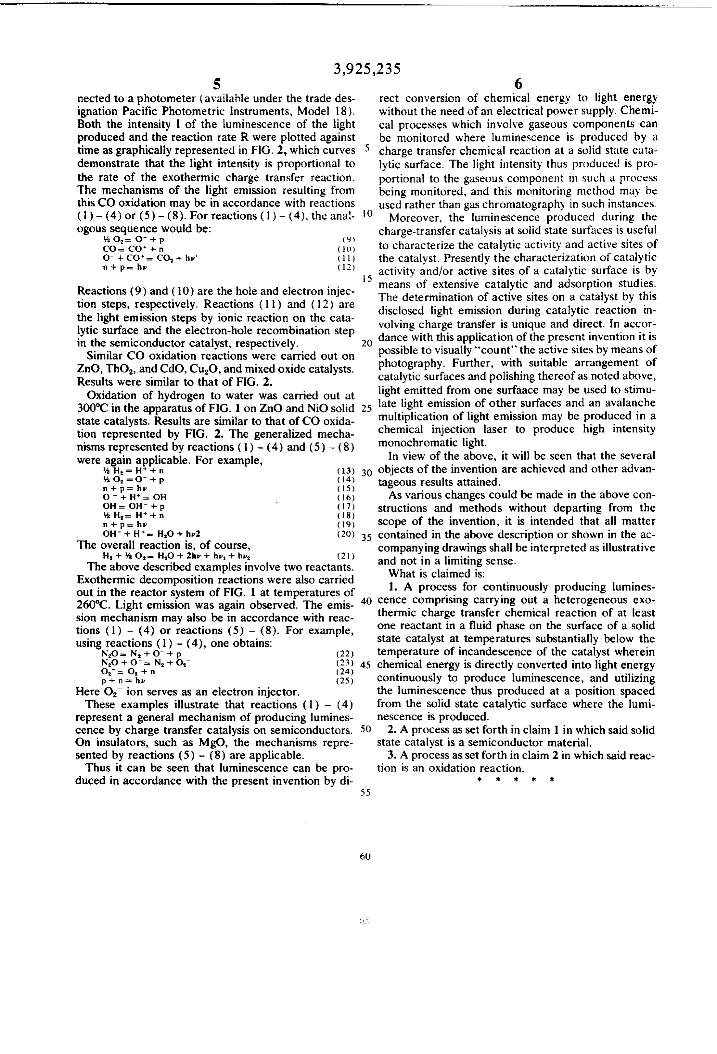
S 6 nected to a photometer (available under the trade des rect conversion of chemical energy to light energy ignation Pacific Photometric instruments, Model 18). without the need of an electrical power supply. Chemi Both the intensity l of the luminescence of the light cal processes which involve gaseous components can produced and the reaction rate R were plotted against be monitored where luminescence is produced by a time as graphically represented in FG. 2, which curves charge transfer chemical reaction at a solid state cata demonstrate that the light intensity is proportional to lytic surface. The light intensity thus produced is pro the rate of the exothermic charge transfer reaction. portional to the gaseous component in such a process The mechanisms of the light emission resulting from being monitored, and this monitoring method may be this CO oxidation may be in accordance with reactions O used rather than gas chromatography in such instances (1) - (4) or (5) - (8). For reactions (1) - (4), the ana Moreover, the luminescence produced during the ogous sequence would be: charge-transfer catalysis at solid state surfaces is useful
CO CO -- { } to characterize the catalytic activity and active sites of
the catalyst. Presently the characterization of catalytic 5 activity and/or active sites of a catalytic surface is by
Reactions (9) and (10) are the hole and electron injec The means of extensive catalytic and adsorption studies. tion steps, respectively. Reactions (ll) and (12) are disclosed determination of active sites on a catalyst by this the light emission steps by ionic reaction on the cata volving charge light emission during catalytic reaction in transfer is unique and direct. In accor lytic surface and the electron-hole recombination step dance with this application in the semiconductor catalyst, respectively. of the present invention it is Similar CO oxidation reactions were carried out on possible to visually "count" the active sites by means of ZnO, Tho, and CdC), CuO, and mixed oxide catalysts, photography. Further, with suitable arrangement of catalytic surfaces and polishing thereofas noted above,
Results were similar to that of FIG. 2.
Oxidation of hydrogen to water was carried out at light late emitted from one surfaace may be used to stimu light emission of other surfaces and an avalanche 300°C in the apparatus of FIG. 1 on ZnO and NiO solid 25 state catalysts. Results are similar to that of CO oxida multiplication chemical of light emission may be produced in a injection laser to produce high intensity tion represented by FIG. 2. The generalized mecha nisms represented by reactions ( ) - (4) and (5) - (8) monochromatic light.
were again applicable. For example, In view of the above, it will be seen that the several H = H* - n (3) 30 objects of the invention are achieved and other advan %. O, = O + p. (14) tageous results attained.
O - H OH (16) As various changes could be made in the above con OH = OH + p. (17) structions and methods without departing from the
n+p = hy (19) scope of the invention, it is intended that all matter OH + H* - HO -- hv2 (2)) 35 contained in the above description or shown in the ac The overall reaction is, of course, companying drawings shall be interpreted as illustrative H -- 4: O HO + 2h - hv - hv, (2) and not in a limiting sense.
The above described examples involve two reactants. What is claimed is:
Exothermic decomposition reactions were also carried 1. A process for continuously producing lumines out in the reactor system of FIG. 1 at temperatures of 40 cence 260C. Light emission was again observed. The emis thermiccomprising charge carrying out a heterogeneous exo transfer chemical reaction of at least sion mechanism may also be in accordance with reac tions (1) - (4) or reactions (5) - (8). For example, one reactant in a fluid phase on the surface of a solid state catalyst at temperatures substantially below the using reactions (1) - (4), one obtains: temperature of incandescence of the catalyst wherein
NO -- O - N + (), (23) 45 chemical energy is directly converted into light energy
p + n = hv (25) continuously to produce luminescence, and utilizing Here O, ion serves as an electron injector. the luminescence thus produced at a position spaced These examples illustrate that reactions (1) - (4) from the solid state catalytic surface where the lumi represent a general mechanism of producing lumines nescence is produced.
cence by charge transfer catalysis on semiconductors. SO 2. A process as set forth in claim 1 in which said solid On insulators, such as MgO, the mechanisms repre state catalyst is a semiconductor material. sented by reactions (5) - (8) are applicable. 3. A process as set forth in claim 2 in which said reac Thus it can be seen that luminescence can be pro tion is an oxidation reaction.
duced in accordance with the present invention by di k k k
Provenance
- Collection
- Cited prior art
- Original PDF
- patentimages.storage.googleapis.com →
- Filed
- 1972-10-30
- Pages
- 6
- Method
- pdftotext (the PDF's own text layer) + pdftoppm 300dpi page scans
- Source
- Google Patents bibliographic record
- Granted
- 1975-12-09
- Inventors
- Vin-Jang Lee; University of Missouri Columbia
- Transcribed from
- patentimages.storage.googleapis.com →