patent · US20120067551A1
Thermal energy storage using supercritical fluids
22 March 2012
Page 1 — bibliographic record
(19) United States (12) Patent Application Publication (10) Pub. No.: US 2012/0067551A1
GANAPATH (43) Pub. Date: Mar. 22, 2012 (54) THERMAL ENERGY STORAGE USING Publication Classification SUPERCRITICAL FLUIDS (51) Int. Cl.
(75) Inventor: GANI. B. GANAPATHI, La (52) U.S. Cl. ................................................... 165/10421 Crescenta, CA (US) (57) ABSTRACT
A thermal energy storage system is described employing (73) Assignee: salternalist of Technology, latent heat storage of a Supercritical fluid instead of typical asadena, (US) phase change materials. Two fundamental thermodynamic concepts are invoked. First, by using the latent heat of liquid/ (21) Appl. No.: 13/237,875 vapor phase change, high energy density storage is feasible. Second, by operating the thermal energy storage system at a higher pressure, the Saturation temperature is increased to (22) Filed: Sep. 20, 2011 operate at molten salt temperatures and above. Beyond the two-phase regime, Supercritical operation permits capturing
Related U.S. Application Data and utilizing heat taking advantage of latent and sensible heat, both in the two-phase regime as well as in Supercritical (60) Provisional application No. 61/384,635, filed on Sep. regime while at the same time, reducing the required Volume 20, 2010. by taking advantage of the high compressibilities.
Page 2
Drawing sheet — no readable text.
Page 3
Drawing sheet — no readable text.
Page 4
Drawing sheet — no readable text.
Page 5
Drawing sheet — no readable text.
Page 6
Drawing sheet — no readable text.
Page 7
Drawing sheet — no readable text.
Page 8
Drawing sheet — no readable text.
Page 9
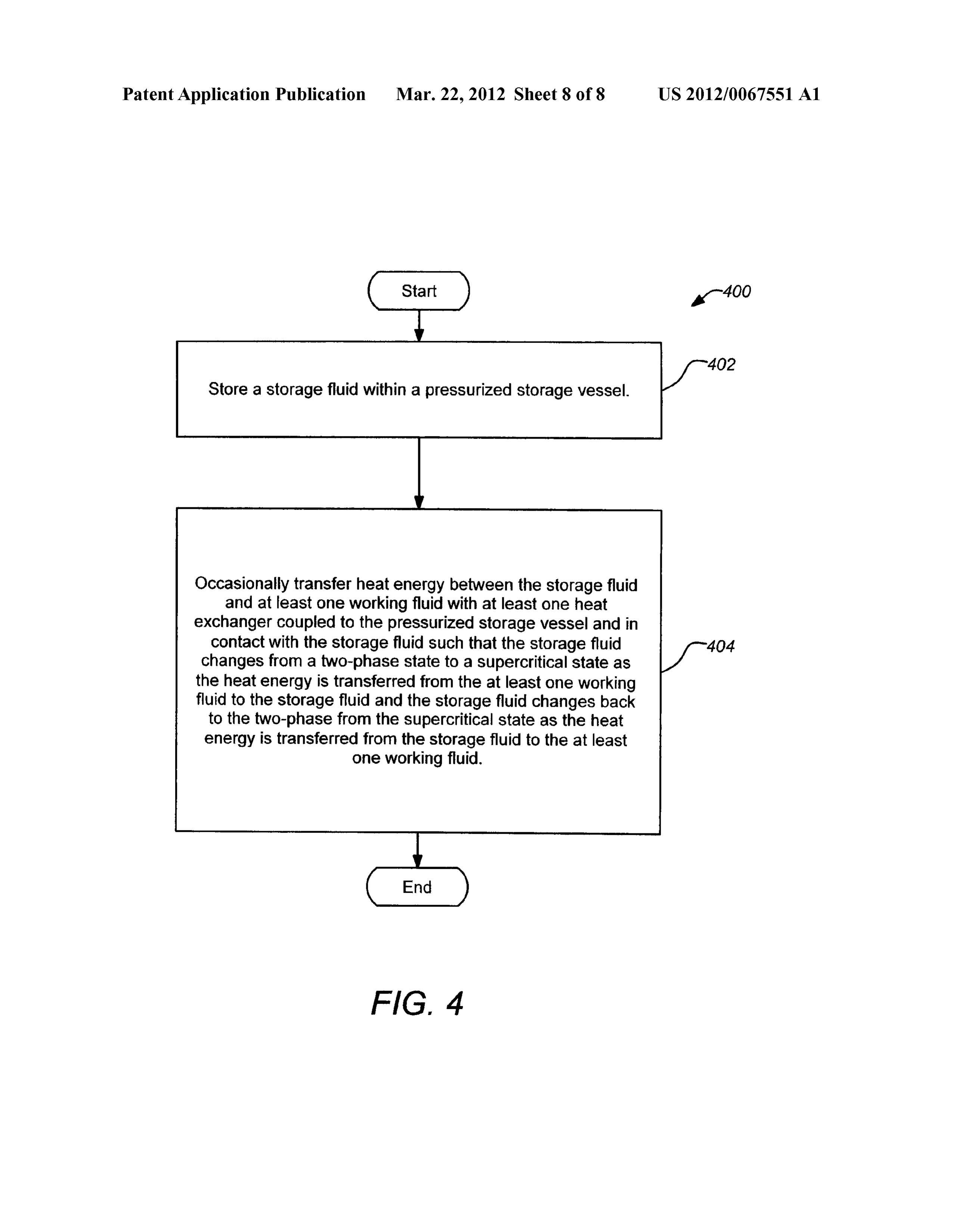
Patent Application Publication Mar. 22, 2012 Sheet 8 of 8 US 2012/0067551A1 Store a storage fluid within a pressurized storage vessel. Occasionally transfer heatenergy between the storage fluid and at least one working fluid with at least one heat exchanger coupled to the pressurized storage vessel and in contact with the storage fluid such that the storage fluid changes from a two-phase state to a supercritical state as the heatenergy is transferred from the at least one working fluid to the storage fluid and the storage fluid changes back to the two-phase from the supercritical state as the heat energy is transferred from the storage fluid to the at least one working fluid.
FIG. 4
Page 10
US 2012/0067551A1 Mar. 22, 2012
THERMAL ENERGY STORAGE USING herein. In terms of cost, cost of the storage material itself, heat SUPERCRITICAL FLUIDS exchanger for charging and discharging the system and the cost for the space and the enclosure for the thermal energy
CROSS-REFERENCE TO RELATED storage are the important factors.
APPLICATIONS
0010. In general, there are three mechanism types for ther 0001. This application claims the benefit under 35 U.S.C. mal energy storage. These mechanisms can be broadly clas S119(e) of the following U.S. provisional patent application, sified as under sensible heat storage, latent heat storage and which is incorporated by reference herein: chemical energy storage. Storage and removal of energy 0002 U.S. Provisional Patent Application No. 61/384, using sensible heat storage involves merely a temperature 635, filed Sept. 20, 2010, and entitled “Thermal Energy Stor change of the storage medium in either Solid, liquid or gasous age with Supercritical Fluids', by Ganapathi (Attorney form. Storage and removal of energy using latent heat Storage Docket CIT-5441-P2). involves a state change of the storage medium, e.g. liquid to
STATEMENT OF GOVERNMENT RIGHTS
gas. Storage and removal of energy using chemical energy storage involves a chemical change in the storage medium, 0003. The invention described herein was made in the e.g. burning hydrogen. Some different specific energy storage performance of work under a NASA contract, and is subject systems that have been studied include two-tank direct, two to the provisions of Public Law 96-517 (35 USC 202) in tank indirect, single-tank thermocline, and thermal energy which the Contractor has elected to retain title. storage media. See http://www.nrel.qov/csp/trouqhnet/ther mal energy storage.html.
BACKGROUND OF THE INVENTION 0011. One example two-tank direct system used mineral 0004. 1. Field of the Invention oil (Caloria) heat transfer fluid which was also used to store 0005. This invention relates to thermal energy storage sys energy for later use (hence the term “direct”). It was first tems. Particularly, this invention relates to thermal energy demonstrated in the Luz trough plant, SEGS and operated storage systems using Supercritical fluids as the storage between 1985 and 1999 to dispatch solar power to meet medium. Southern California Edison (SCE) winter evening peak 0006 2. Description of the Related Art demand period needs. The fluid was later replaced with Ther 0007 Solar thermal power (also referred to as Concen minol VP-1, which is a higher temperature fluid (but unfor trated Solar Power CSPI) is currently viewed as one of the tunately, a higher vapor pressure fluid as well). The operating most cost effective options to convert Solar radiation into temperature of these systems is limited to less than approxi electricity. Example systems employing Solar thermal power mately 370° C.
have been operationally proven in California since the mid 0012 Another demonstrated energy storage system is the 1980s. In 1984, the first solar electric generating systems two-tank indirect system. The term “indirect,” refers to the (SEGS) plant was installed in southern California by Luz fact that the storage fluid is different from the HTF. The heat International, Inc. The most recently commissioned plant was from the HTF is transferred to one of the tanks which is then in 2008, a 64 MW plant, called the Nevada Solar One. Pur transferred to the power generation system when needed by chase agreements for nearly 1 GW of solar thermal from the discharging the fluid into another tank through the use of heat Nevada Solar One have been completed, or are in the final exchangers. Molten salt eutectic mixtures of NaNO and stages, in the Southwest U.S. KNO are used for the storage medium. Due to its develop 0008. One advantage of parabolic trough solar power ment maturity, this system is currently favored over the other plants is their potential for storing Solar thermal energy for options even though the costs of the storage fluid are very use during non-Solar periods and to dispatch the energy when high. The most advanced implementation of its type is the it is most needed. As a result, thermal energy storage (TES) Andasol 1 plant in Spain, with a storage capacity of 1 GWh allows parabolic trough Solar power plants to achieve higher (under 7.5 hr full load operation). annual capacity factors—from approximately 25% without 0013 In a single-tank thermocline system, a single tank thermal storage up to 70% or more with it. Other related stores both the hot fluid as well as the cold fluid, operating on advantages include the capability of buffering during tran the principle that a hot fluid is lighter than cold and will sient weather conditions, improved dispatchability or time remain at the top of the tank. Sandia National Laboratories shifting, more even distribution of electricity production and has demonstrated a 2.5 MWh packed-bed thermocline system capability to achieve full load operation of the steam cycle at with molten salt fluid and quartzite rock and sand for filler high efficiency. material. The cost of Such a system depends on the storage 0009. Thermal energy storage systems are broadly rated fluid cost. The system has to be well designed to maintain the on the following technical requirements. High energy density thermocline Zone (the Zone between the hot and cold fluids) of the storage material (per-unit mass or per-unit volume) and so that it does not expand to fill the entire tank, at which point good heat transfer between heat transfer fluid (HTF) and the the system is no longer operational. storage medium are primary rating factors. In addition, 0014. One other tested form of thermal energy storage mechanical and chemical stability of storage material and employs a thermal energy storage (TES) medium. Solid TES chemical compatibility between HTF, heat exchanger and/or media Such as concrete, castable ceramic materials are being storage medium are important considerations. Complete considered as potential TES candidates. This option is prima reversibility for a large number of charging/discharging rily driven by the low cost of the solid media itself as well as cycles, low thermal losses, and ease of control are also con other advantages, such as long life. In this case, an HTF siderations. See e.g., Herrmann et al., “Overview on Thermal passes through an array of pipes embedded in the Solid Storage Systems.” FLABEG Solar Int. GmbH, Dave Kearney medium to transfer the thermal energy to and from the (Kearney & Assoc), which is incorporated by reference medium during plant operations. The German Aerospace
Page 11
US 2012/0067551A1 Mar. 22, 2012
Center (DLR) and Ciemat have performed initial testing of feasible. Second, by operating the thermal energy storage castable ceramic and high-temperature concrete in a thermal system at a higher pressure, the Saturation temperature is energy Storage System. increased to operate at molten salt temperatures and above. 00.15 All the technologies described above rely on sen Beyond the two-phase regime, Supercritical operation per sible heatenergy. In contrast, phase change materials (PCMs) mits capturing and utilizing heat taking advantage of latent rely on the latent heat energy and can therefore store very and sensible heat, both in the two-phase regime as well as in large amounts of heat. The DOE had studied the possibility of Supercritical regime while at the same time, reducing the using PCM for heat storage in the 1980's, but did not pursue required Volume by taking advantage of the high compress it further primarily due to the complexities of the required ibilities.
system and the operational uncertainty over lifetime of the
PCMs. Work performed by Luz International Ltd. on the use 0020. A typical embodiment of the invention comprises a of low temperature salts such as NaNO, KNO, and KOH thermal energy storage apparatus, including a pressurized indicated that the performance of the materials degrade after storage vessel, a storage fluid within the pressurized storage a moderate number of freeze-melt cycles. Additionally, the vessel, and at least one heat exchanger coupled to the pres heat transfer characteristics for PCMs have two major prob Surized storage vessel and in contact with the storage fluid to lems. They have relatively poor thermal conductance across occasionally transfer heat energy between the storage fluid regions of solid PCM compared to convective heat transfer in and at least one working fluid. The storage fluid changes from the heat transfer fluid (HTF). In addition, there is a "pinch a two-phase state to a Supercritical state as the heat energy is point problem which refers to the relatively small tempera transferred from the at least one working fluid to the storage ture differences between the PCM and the charging or dis fluid and changes back to the two-phase from the Supercritical charging HTF which occurs in the heat exchanger where the state as the heatenergy is transferred from the storage fluid to PCM is just dropping below or rising above the phase change the at least one working fluid. The storage fluid in a dis temperature. At these points, large heat transfer areas are charged State (when Substantially all heat energy has been needed for the transfer of heat due to the small temperature extracted to perform work) is in a two-phase state comprising differences. liquid and vapor. In its charged State (heat storage mode), the 0016. More recently, the DOE has reinitiated funding for storage fluid has been converted to a Supercritical state where TES and HTF and has funded several proposals, representing the energy is stored as heat at a pressures and temperatures approximately S68M in 2008, to look at alternate technolo above the fluid critical point.
gies as well as address many of the problems with prior 0021. In some embodiments, at least one of the heat approaches. However, the proposed technologies were either exchangers is disposed within the pressurized storage vessel. sensible heat-based approaches or very advanced technolo The working fluid may comprise a heat Source working fluid gies, where it is not clear whether Such technologies will Such that the heat exchanger within the pressurized storage deliver adequate low-cost energy storage. vessel receives the heat source working fluid to transfer the 0017. The U.S. Department of Energy (DOE) has identi heat energy from the heat source working fluid to the storage fied improved thermal energy storage (TES) as the most criti fluid. In one example, the heat source working fluid may be cal technology development needed to allow solar thermal coupled to a solar thermal plant. Similarly, the working fluid power to replace non-renewable power generation sources may comprise a heat sink working fluid Such the heat (e.g. coal and gas). The DOE estimates that the cost of TES exchanger within the pressurized storage vessel receives the must be around $20/kWh or better to make a significant heat sink working fluid to transfer the heat energy from the impact on power production with CSP by bringing the cost storage fluid to the heat sink working fluid. For example, the down from current 11-13:/kWh to approximately 7:/kWh by heat sink working fluid may be coupled to a steam generator 2015 with 6 hours of storage for intermediate power markets generating electrical power.
and to approximately 5:/kWh by 2020 with 16 hours of 0022. A number of suitable storage fluids have been iden storage for baseload power markets. The currently favored tified. For example, the storage fluid may comprise glycerol, thermal storage option is two-stage indirect storage with mol pthalic anhydride, benzoic acid, 3.4Xylenol, or iodobenzene. ten salts (eutectic mixtures of NaNO, and KNO) for which In addition, the storage fluid may comprise a polyaromatic the fluid costs alone range from S27-S54/kWh. hydrocarbon (PAH) such as naphthalene, methylnaphlene, 0018. In view of the foregoing, there is a need in the art for dimethylnapthalene, or biphenyl. In addition, ionic fluids improved apparatuses and methods for energy storage. There present another class of suitable working fluids. Glycerol and is particularly a need for Such apparatuses and methods using naphthalene are currently identified as strong options. Supercritical fluids. In addition, Such suitable systems and methods are needed that are capable of achieving the DOE 0023. A typical method embodiment of the invention com cost goal of S20/kWh. In addition, such systems and methods prises storing a storage fluid within a pressurized storage are needed to address many of the issues faced by the current vessel, and occasionally transferring heat energy between the baseline approach of a two-tank molten salt storage. These storage fluid and at least one working fluid with at least one and other needs are met by embodiments of the present inven heat exchanger coupled to the pressurized storage vessel and tion as detailed hereafter. in contact with the storage fluid such that the storage fluid changes from a two-phase State to a Supercritical state as the
SUMMARY OF THE INVENTION heat energy is transferred from the at least one working fluid to the storage fluid and the storage fluid changes back to the 0019. A thermal energy storage system is described two-phase from the Supercritical state as the heat energy is employing latent heat storage of a Supercritical fluid instead transferred from the storage fluid to the at least one working of typical phase change materials. Two fundamental thermo fluid. This method embodiment of the invention may be fur dynamic concepts are invoked. First, by using the latent heat ther modified consistent with the apparatus embodiments of liquid/vapor phase change, high energy density storage is described herein.
Page 12
US 2012/0067551A1 Mar. 22, 2012
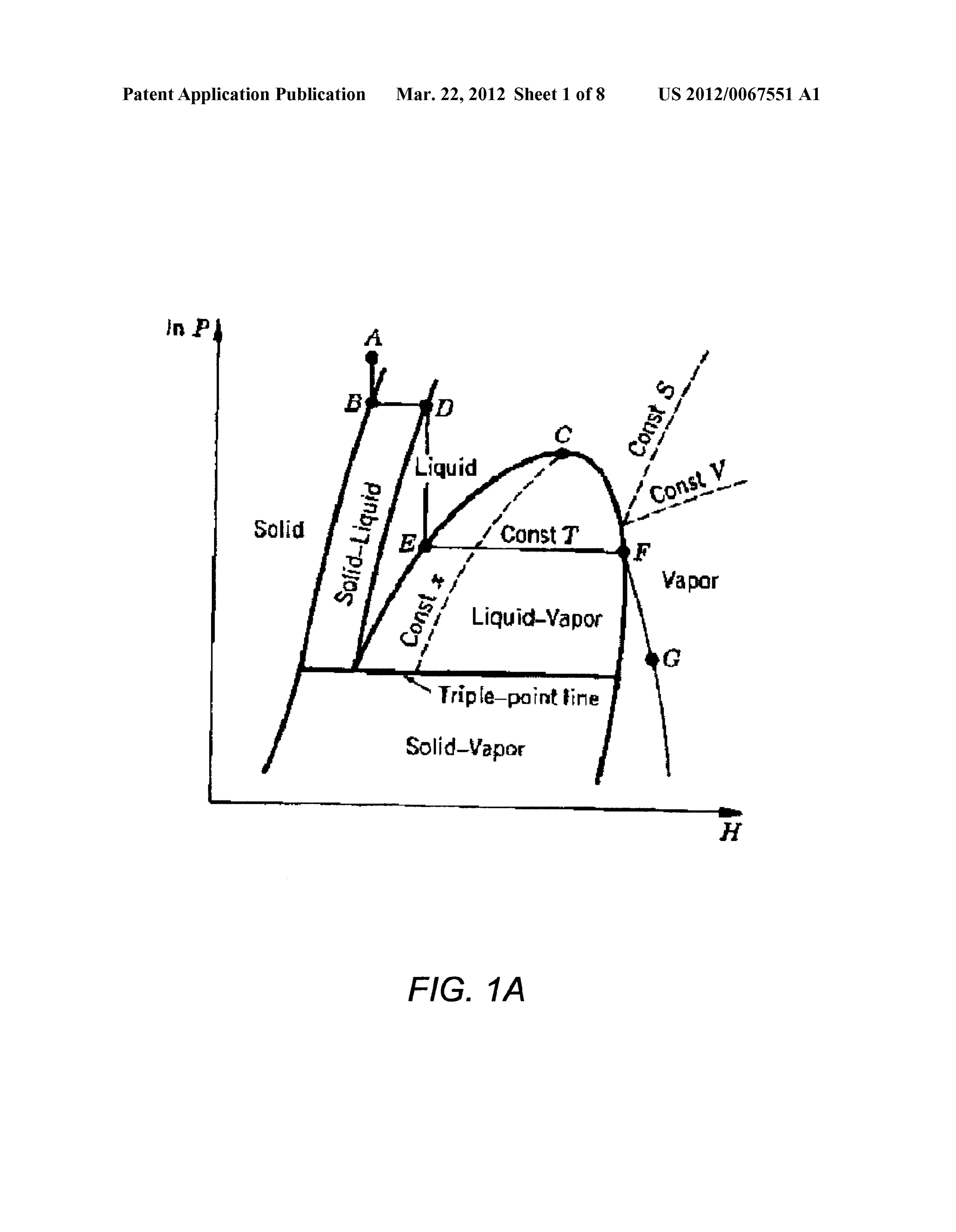
0024. Another typical embodiment of the invention may 0037. As previously mentioned, a thermal energy storage comprise a thermal energy storage apparatus, including a system may be described where a storage fluid remains in a pressurized storage vessel means for storing a storage fluid Supercritical state within a closed system comprising a pres means for storing heatenergy, and at least one heat exchanger Surized storage vessel. The thermal energy storage system means for occasionally transferring the heat energy between operates at a higher pressure to increase the Saturation tem the storage fluid means and at least one working fluid means perature. Heat exchangers may be disposed within the closed for transferring the heat energy, the at least one heat pressurized storage vessel Such that a heat source working exchanger means coupled to the pressurized storage vessel fluid (e.g. from a Solar thermal plant) delivers heatenergy and means and in contact with the storage fluid means. The Stor a heat sink working fluid (e.g. from a steam generator) age fluid means changes from a two-phase state to a Super removes heat energy. The principle of the invention may be critical state as the heat energy is transferred from the at least illustrated with a discussion of the phase change of supercriti one working fluid to the storage fluid and changes back to the cal fluids hereafter.
two-phase from the Supercritical state as the heat energy is transferred from the storage fluid to the at least one working 0038 2. Phase Change of Supercritical Fluids fluid. This embodiment of the invention may be further modi 0039 FIG. 1 is an exemplary phase diagram of a pure fied consistent with the apparatus or method embodiments component. The "tie-line' EF represents the two-phase described herein. regime. By adding heat into the liquid at E, the enthalpy of the liquid/vapor system increases until it is all vapor at F. During
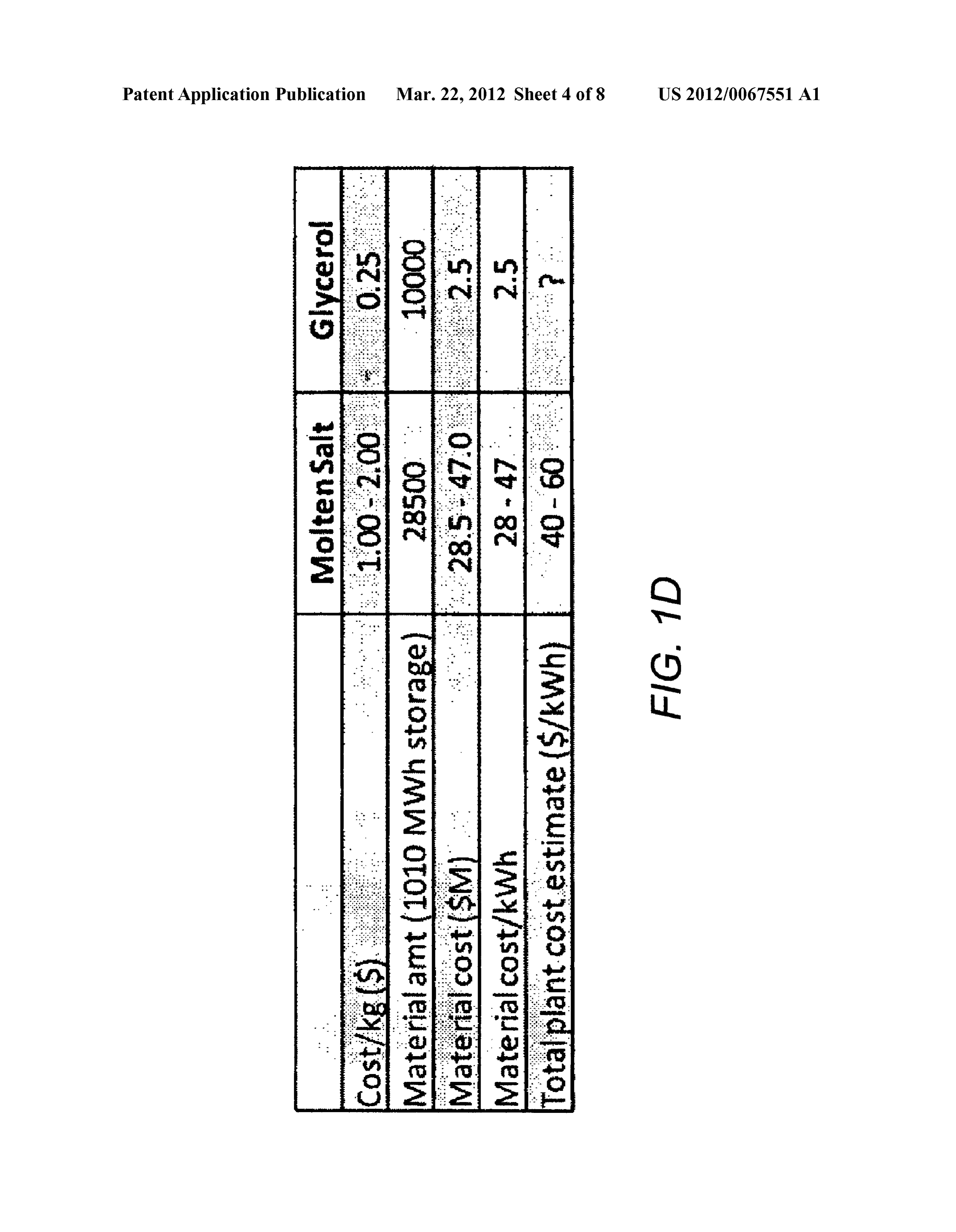
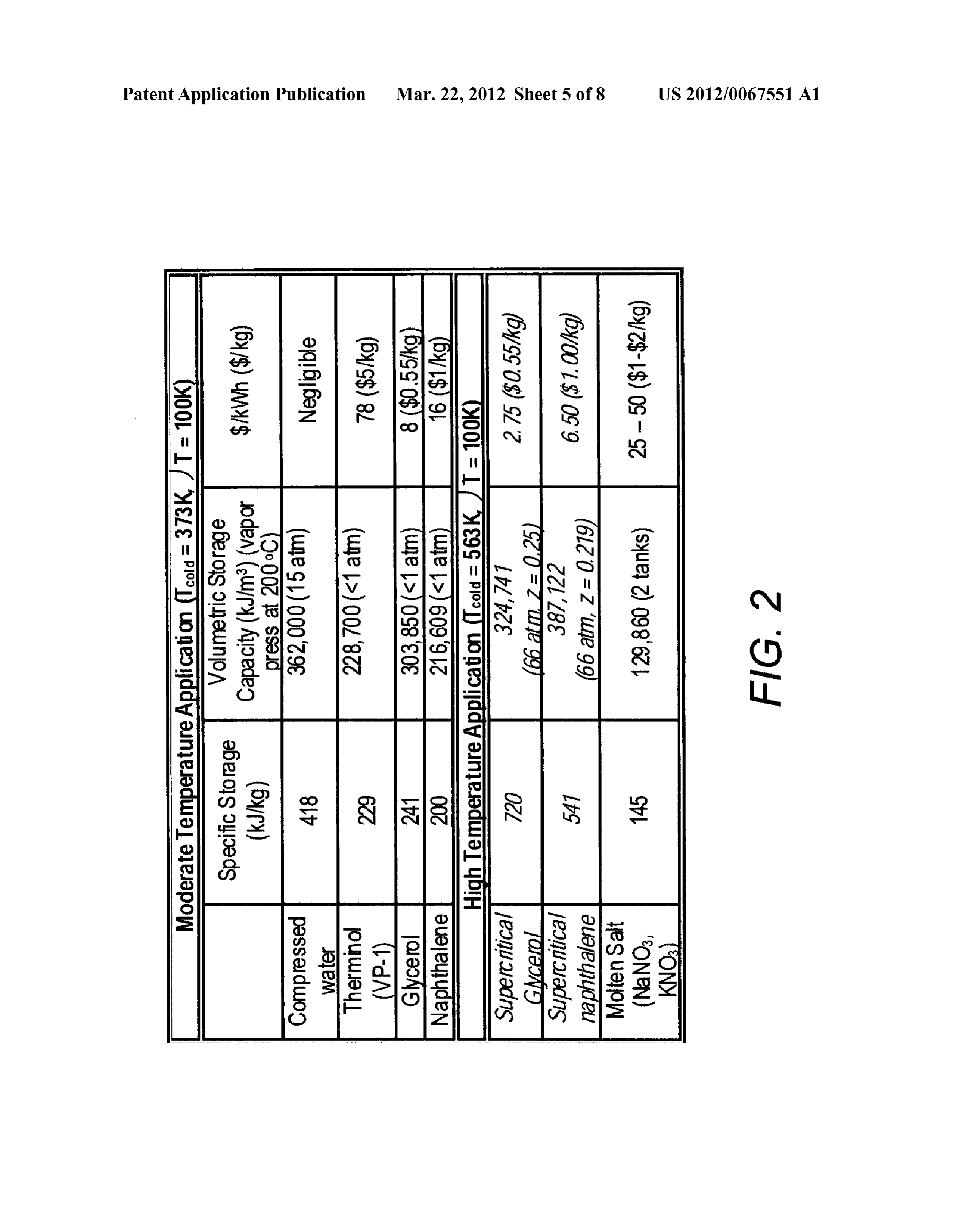
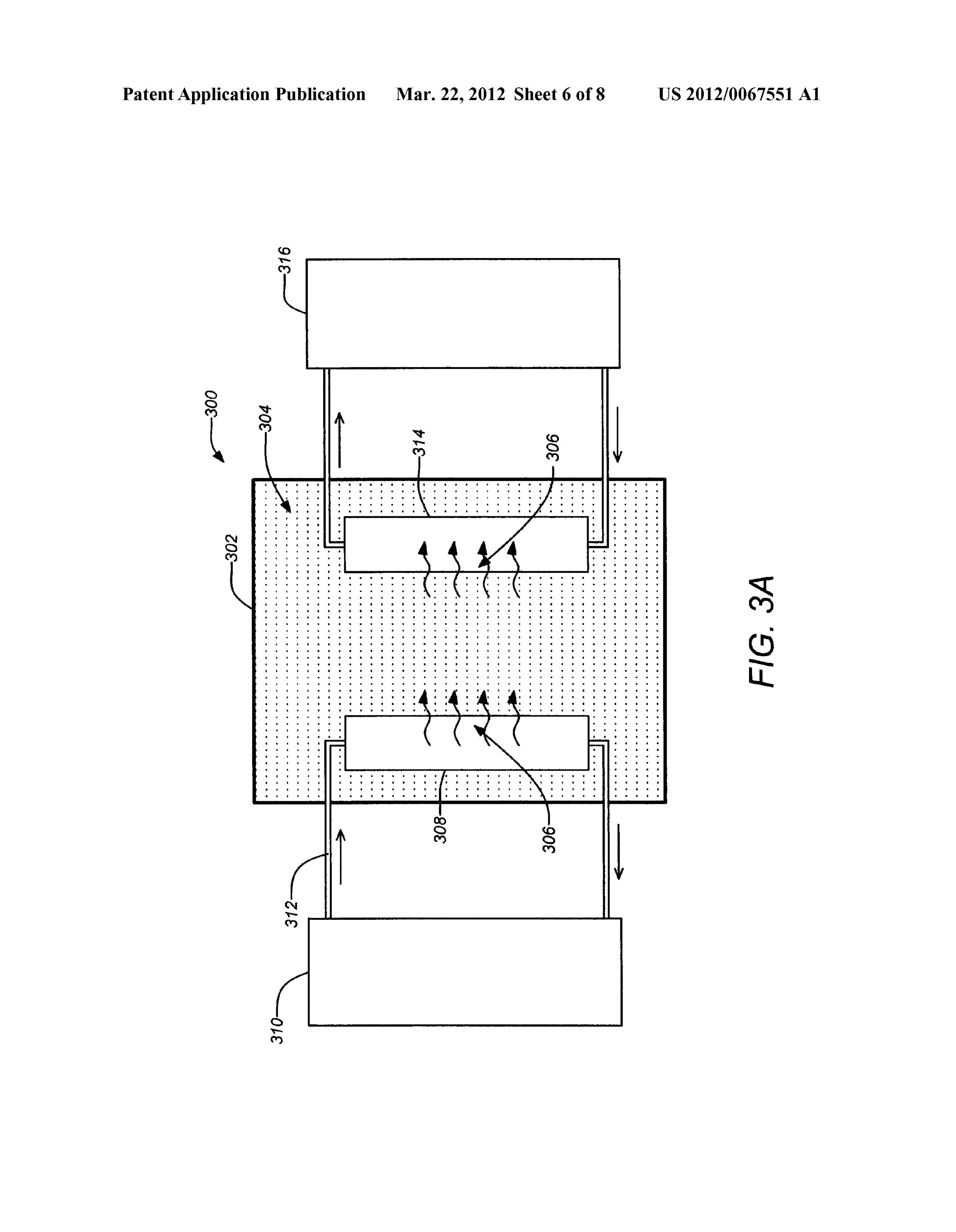
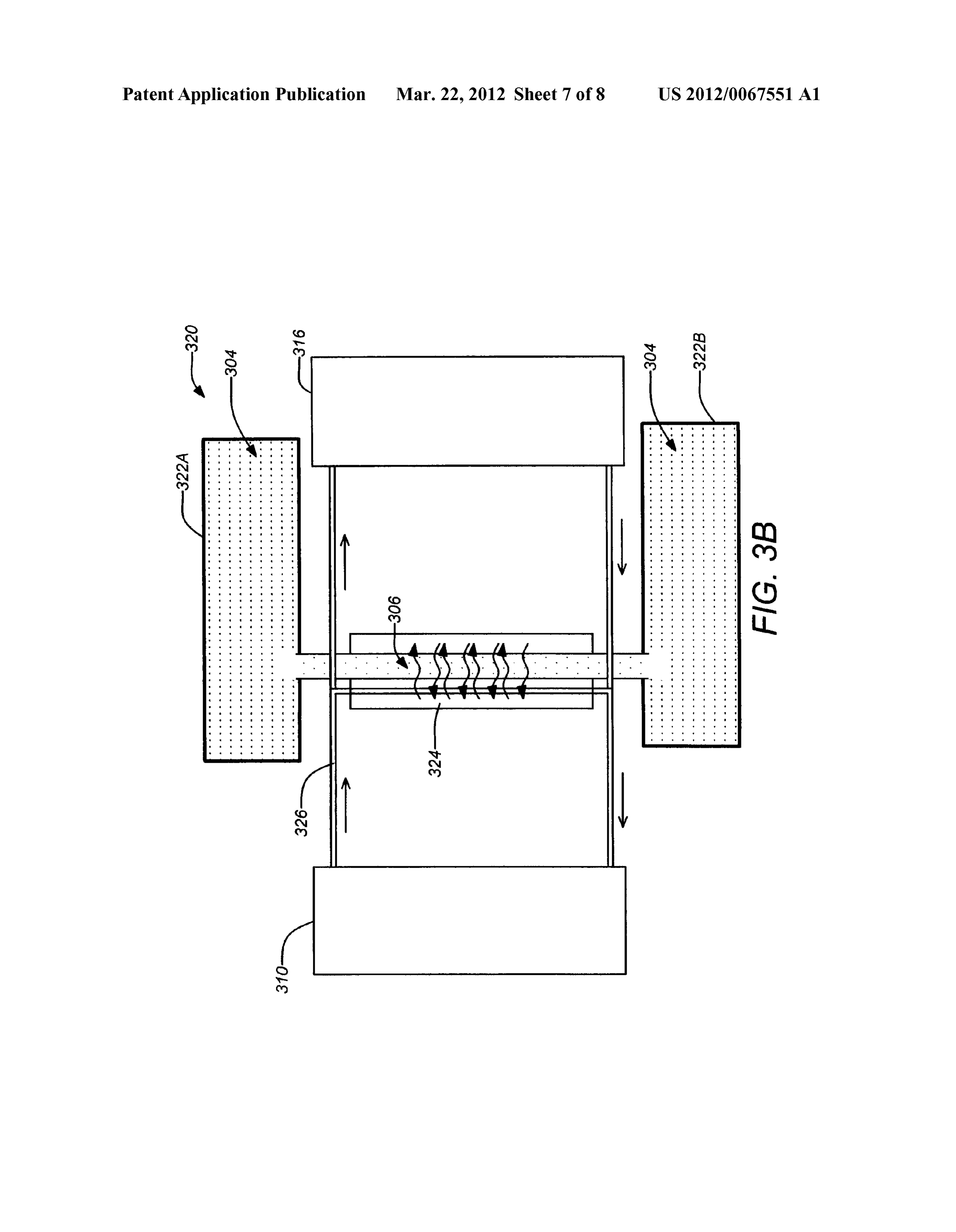
BRIEF DESCRIPTION OF THE DRAWINGS this phase change in an enclosed system as more heat is 0025 Referring now to the drawings in which like refer introduced, the pressure (and temperature) of the system ence numbers represent corresponding parts throughout: increases till a new equilibrium point is reached. Thus, it is 0026 FIG. 1A is an exemplary phase diagram of a pure possible to design a system where the entire fluid is in a component; supercritical state (either above or to the right of point C). In 0027 FIG. 1B is table showing thermodynamic properties Such a Supercritical state, by allowing a higher system pres for selected Supercritical thermal energy storage fluid; sure, the volume of the overall system may be optimized to be 0028 FIG. 1C shows the vapor pressure of glycerol as a more compact. However, the system pressure need not be function of temperature; excessive with a judicious choice of storage fluid. In a sense, 0029 FIG.1D shows a table summarizing a comparison of this concept operates by borrowing a principle similar to using pressurized and glycerol in a Supercritical state com steam accumulators which are employed in chemical process pared to the reference case of the molten salt thermal energy plants to provide short duration thermal energy storage pri Storage System; marily for buffering variations in heat production. However, 0030 FIG. 2 shows a table of sample calculation results there are some key differences. For example, in this case for glycerol and naphthalene as representative storage fluids storage is performed with a fixed amount of fluid that does not in a Supercritical fluid thermal energy storage system; change and heat transfer within the storage medium is per 0031 FIG.3A is schematic drawing an exemplary thermal formed entirely within the fluid media through internal heat energy storage apparatus using a single tank according to an exchangers.
embodiment of the invention; 0040. As mentioned above, the selection of fluid is crucial 0032 FIG.3B is schematic drawing an exemplary thermal to the operation of the TES in an embodiment of the present energy storage apparatus using two tanks according to an invention. Embodiments of the invention may employ certain embodiment of the invention; and organic fluids. The selection criteria for the fluid are based on 0033 FIG. 4 is a flowchart of an exemplary method of a high heat of vaporization, AH, and a high critical tempera storing thermal energy storage according to an embodiment ture, T, and boiling point, T. Some Suitable fluids that can of the invention. provide significant heat storage temperatures close to molten salt at 384° C. have been identified. Four hundred organic
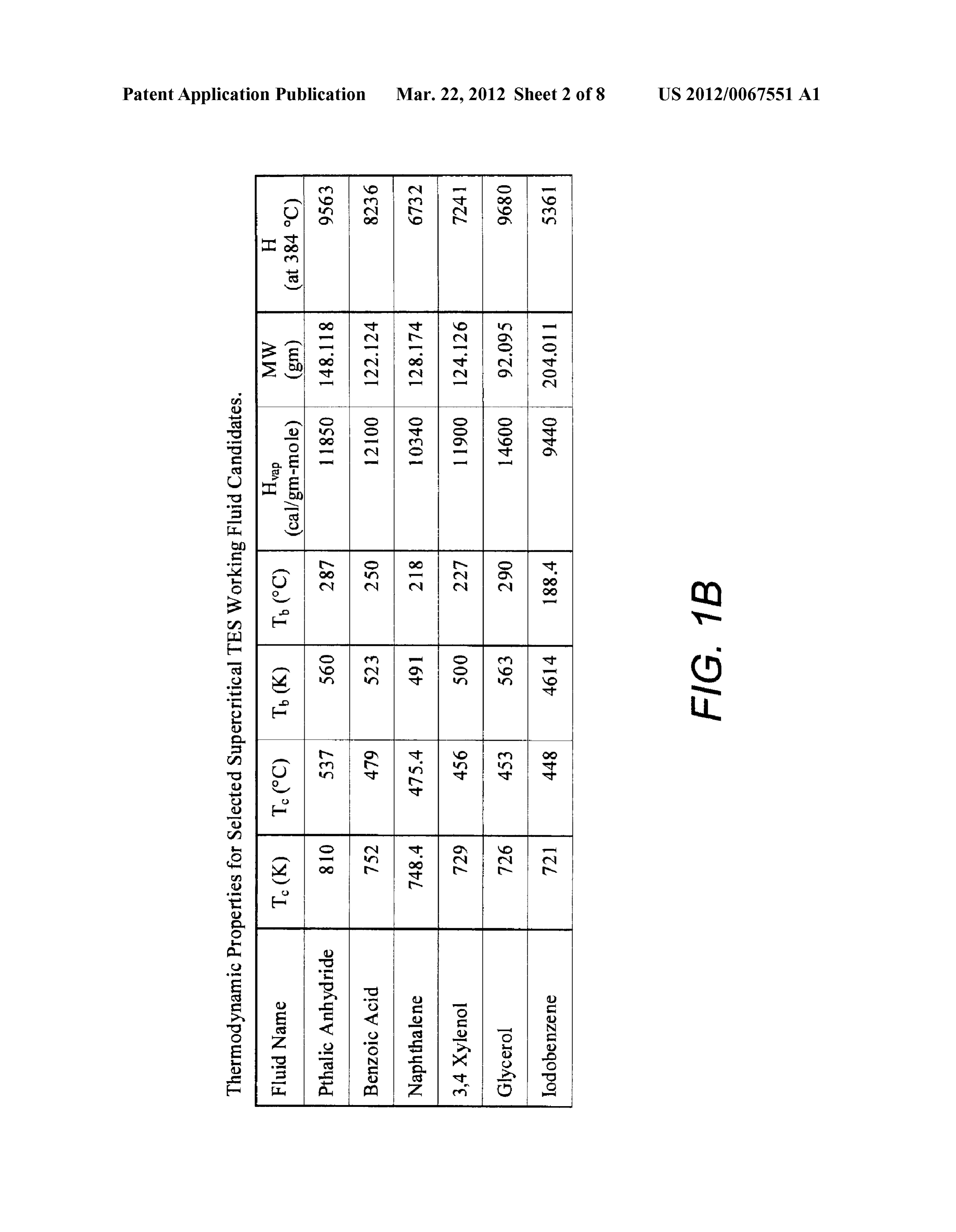
DETAILED DESCRIPTION OF THE PREFERRED fluids were rapidly reviewed for a suitable combination of EMBODIMENT thermodynamic properties as described above. The list was reduced to approximately ten liquids based on a preference 0034 1. Overview for liquids with a good combination of thermodynamic prop 0035. A new thermal energy storage system has been pro erties, material compatibilities and low cost. Thermodynamic posed using pressurized Supercritical fluids, which provides properties were estimated using techniques outlined in Reid numerous advantages including a simpler system design, much lower fluid storage costs, improved system perfor et al., “The properties of gases and liquids.” which is incor mance overall. Working with high temperature HTF and ther porated by reference herein. Candidate fluids for embodi mal storage yields higher system performance. ments of the invention were identified by cross-checking the 0036. The thermal energy storage system may be estimations with data in the literature at discrete temperature values.
described as employing latent heat storage of a Supercritical fluid instead of typical phase change materials. Two funda 0041 FIG.1B is table showing thermodynamic properties mental thermodynamic concepts are invoked. First, by using for selected Supercritical thermal energy storage fluid. Ther the latent heat of liquid/vapor phase change, an efficient sys modynamic properties for preferred fluids for embodiments tem is developed which will provide a constant sink/source of of the invention are shown in the table based on the estimation heat. Second, by operating the thermal energy storage system approaches recommended by Reid, et al., as described. at a higher pressure, the saturation temperature is increased to I0042. The AH, at different temperatures were estimated operate at molten salt temperatures and above. by the following equation.
Page 13
US 2012/0067551A1 Mar. 22, 2012
amount of storage medium needed. Repeating these calcula tions for supersaturated glycerol at 450° C., the amount of
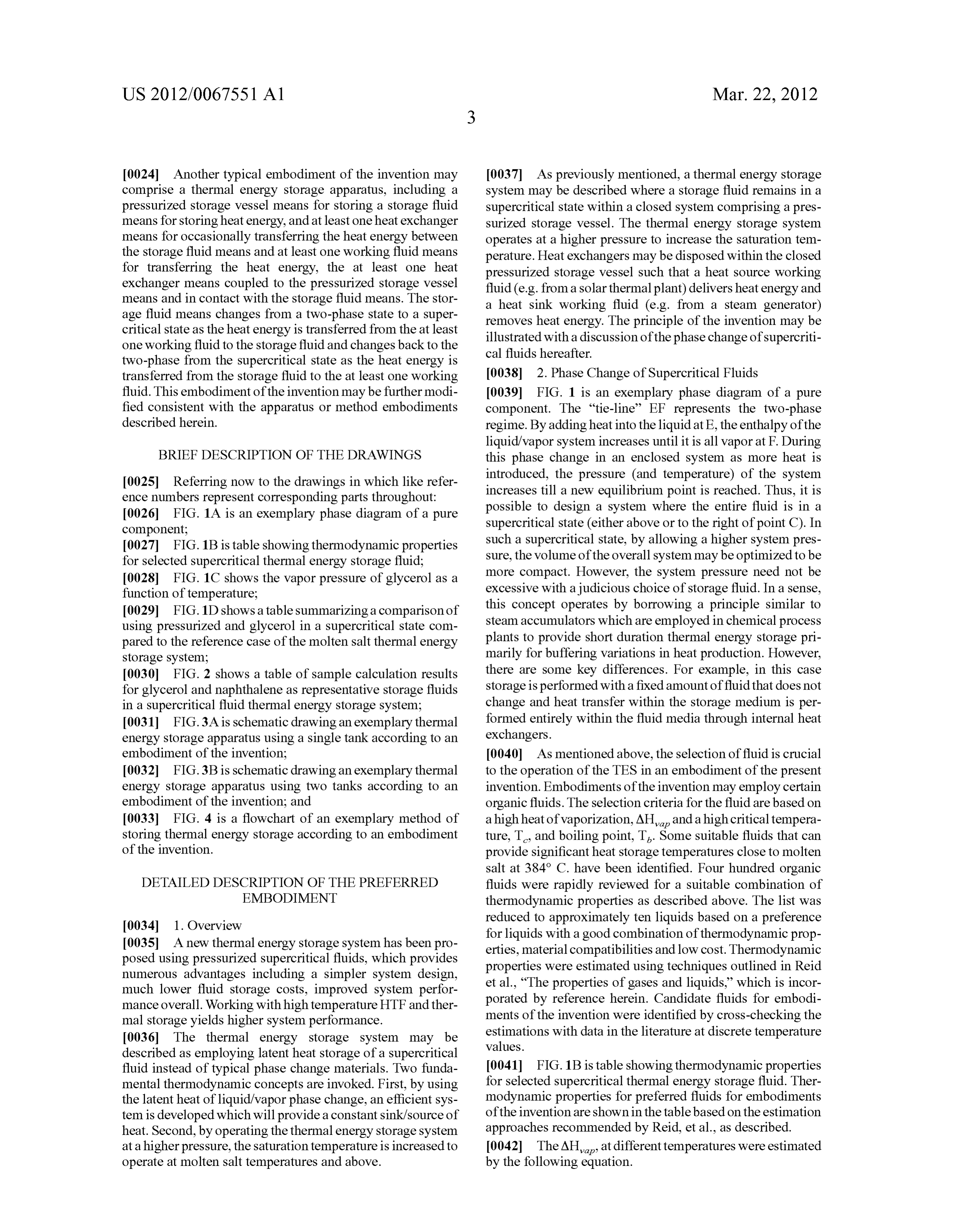
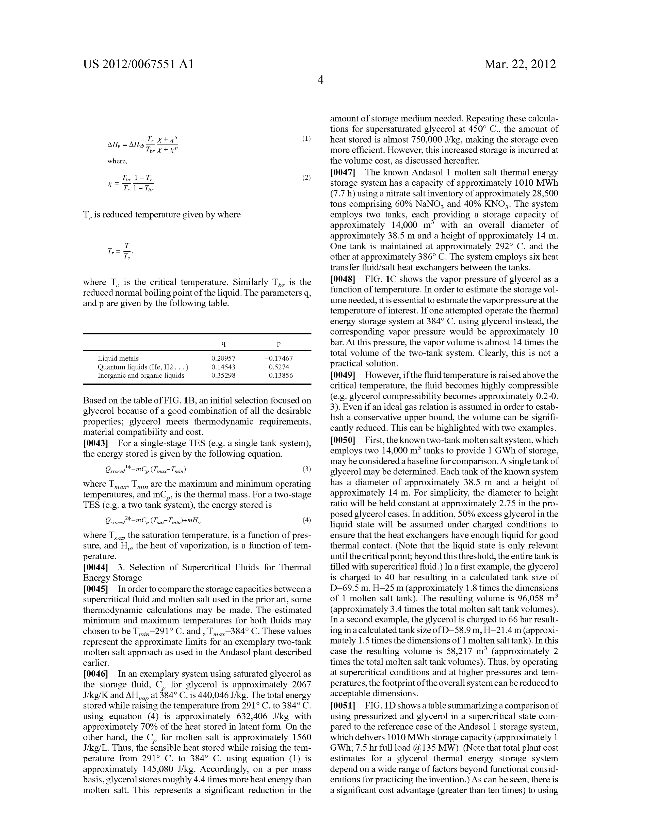
AH = AH, TheT at++ P (1)1 heat stored is almost 750,000 J/kg, making the storage even more efficient. However, this increased storage is incurred at where, the Volume cost, as discussed hereafter. T, 1 - T. (2) 0047. The known Andasol 1 molten salt thermal energy A - T, 1 T. storage system has a capacity of approximately 1010 MWh (7.7h) using a nitrate salt inventory of approximately 28,500 tons comprising 60% NaNO, and 40% KNO. The system
T, is reduced temperature given by where employs two tanks, each providing a storage capacity of approximately 14,000 m with an overall diameter of approximately 38.5 m and a height of approximately 14 m.
One tank is maintained at approximately 292 C. and the other at approximately 386°C. The system employs six heat transfer fluid/salt heat exchangers between the tanks.
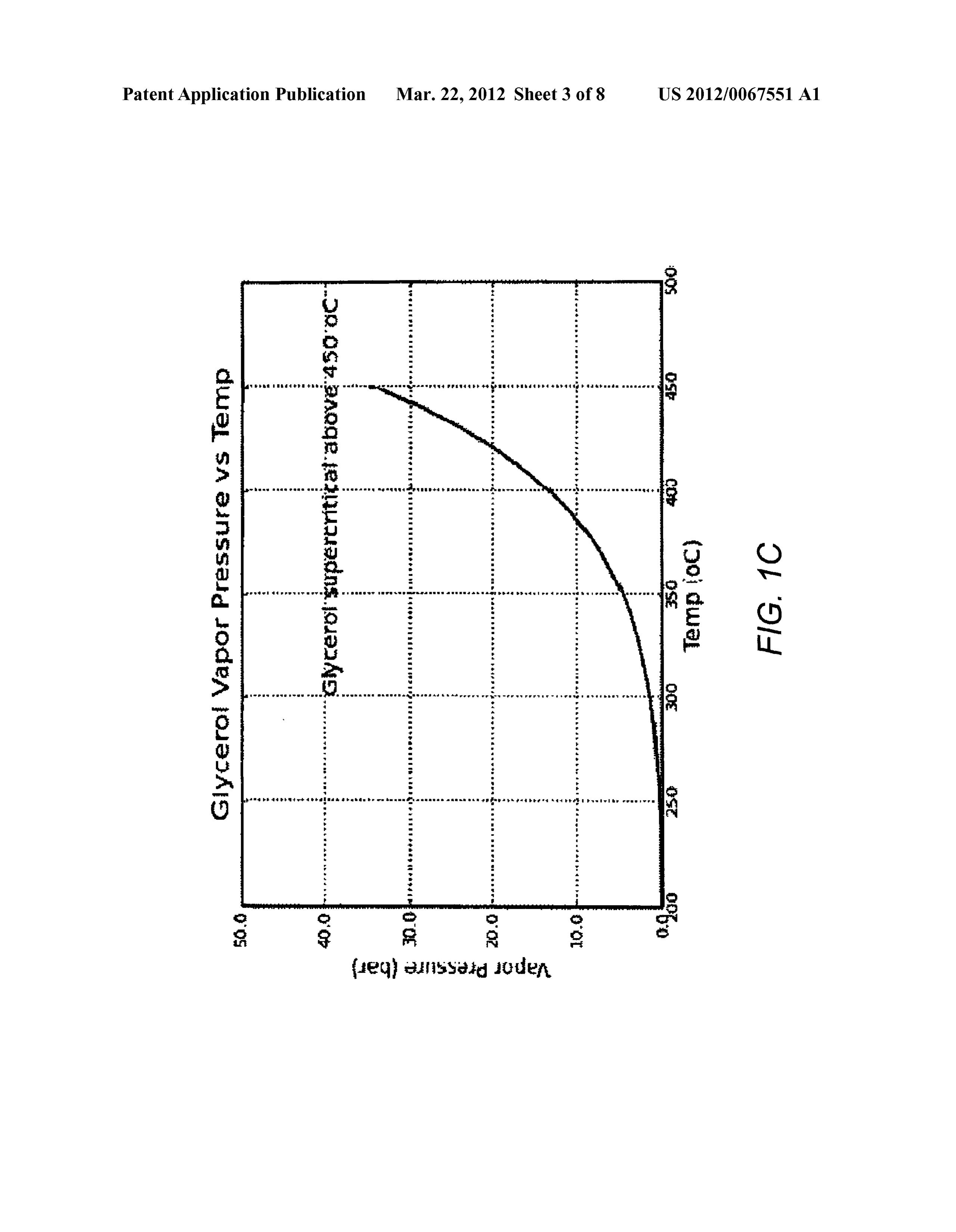
where T is the critical temperature. Similarly T is the 0048 FIG. 1C shows the vapor pressure of glycerol as a reduced normal boiling point of the liquid. The parameters q, function of temperature. In order to estimate the storage Vol and p are given by the following table. ume needed, it is essential to estimate the vapor pressure at the temperature of interest. If one attempted operate the thermal energy storage system at 384°C. using glycerol instead, the corresponding vapor pressure would be approximately 10
C p bar. At this pressure, the vapor volume is almost 14 times the
Liquid metals 0.20957 -0.17467 total volume of the two-tank system. Clearly, this is not a Quantum liquids (He, H2. . . ) O.14543 O.S274 practical solution.
Inorganic and organic liquids O.35298 O.13856 0049. However, if the fluid temperature is raised above the critical temperature, the fluid becomes highly compressible
Based on the table of FIG. 1B, an initial selection focused on (e.g. glycerol compressibility becomes approximately 0.2-0. glycerol because of a good combination of all the desirable 3). Even if an ideal gas relation is assumed in order to estab properties; glycerol meets thermodynamic requirements, lish a conservative upper bound, the volume can be signifi material compatibility and cost. cantly reduced. This can be highlighted with two examples. 0043. For a single-stage TES (e.g. a single tank system), 0050 First, the known two-tank molten salt system, which the energy stored is given by the following equation. employs two 14,000 m tanks to provide 1 GWh of storage, may be considered a baseline for comparison. A single tank of
Qorod"-mC (Tina-Tain) (3) glycerol may be determined. Each tank of the known system where T, T, are the maximum and minimum operating has a diameter of approximately 38.5 m and a height of temperatures, and mC, is the thermal mass. For a two-stage approximately 14 m. For simplicity, the diameter to height TES (e.g. a two tank system), the energy stored is ratio will be held constant at approximately 2.75 in the pro posed glycerol cases. In addition, 50% excess glycerol in the
Qi'-mC (Tai-Tai.)+mH, (4) liquid State will be assumed under charged conditions to where T, the saturation temperature, is a function of pres ensure that the heat exchangers have enough liquid for good Sure, and H, the heat of vaporization, is a function of tem thermal contact. (Note that the liquid state is only relevant perature. until the critical point; beyond this threshold, the entire tank is 0044) 3. Selection of Supercritical Fluids for Thermal filled with supercritical fluid.) In a first example, the glycerol Energy Storage is charged to 40 bar resulting in a calculated tank size of 0045. In order to compare the storage capacities between a D=69.5 m, H=25 m (approximately 1.8 times the dimensions Supercritical fluid and molten salt used in the prior art, some of 1 molten salt tank). The resulting volume is 96.058 m thermodynamic calculations may be made. The estimated (approximately 3.4 times the total molten salt tank Volumes). minimum and maximum temperatures for both fluids may In a second example, the glycerol is charged to 66 bar result chosen to be T291° C. and, T-384°C. These values ing in a calculated tanksize of D=58.9 m, H=21.4 m (approxi represent the approximate limits for an exemplary two-tank mately 1.5 times the dimensions of 1 molten salt tank). In this molten salt approach as used in the Andasol plant described case the resulting volume is 58.217 m (approximately 2 earlier. times the total molten salt tank Volumes). Thus, by operating 0046. In an exemplary system using Saturated glycerol as at Supercritical conditions and at higher pressures and tem the storage fluid, C for glycerol is approximately 2067 peratures, the footprint of the overall system can be reduced to J/kg/K and AH, at 384°C. is 440,046J/kg. The total energy acceptable dimensions.
stored while raising the temperature from 291° C. to 384°C. 0051 FIG.1D shows a table summarizing a comparison of using equation (4) is approximately 632,406 J/kg with using pressurized and glycerol in a Supercritical state com approximately 70% of the heat stored in latent form. On the pared to the reference case of the Andasol 1 storage system, other hand, the C for molten salt is approximately 1560 which delivers 1010 MWh storage capacity (approximately 1 J/kg/L. Thus, the sensible heat stored while raising the tem GWh: 7.5 hr full load (a 135 MW). (Note that total plant cost perature from 291° C. to 384° C. using equation (1) is estimates for a glycerol thermal energy storage system approximately 145,080 J/kg. Accordingly, on a per mass depend on a wide range of factors beyond functional consid basis, glycerol stores roughly 4.4 times more heatenergy than erations for practicing the invention.) As can be seen, there is molten salt. This represents a significant reduction in the a significant cost advantage (greater than ten times) to using
Page 14
US 2012/0067551A1 Mar. 22, 2012
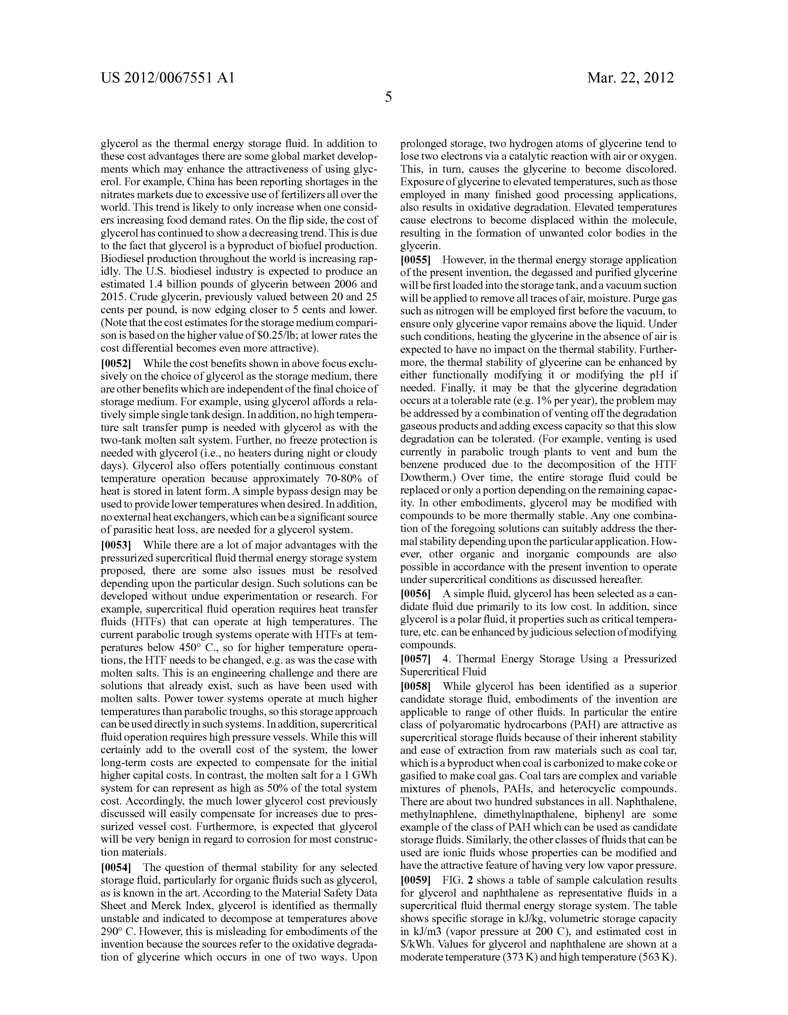
glycerol as the thermal energy storage fluid. In addition to prolonged storage, two hydrogen atoms of glycerine tend to these cost advantages there are some global market develop lose two electrons via a catalytic reaction with air or oxygen. ments which may enhance the attractiveness of using glyc This, in turn, causes the glycerine to become discolored. erol. For example, China has been reporting shortages in the Exposure of glycerine to elevated temperatures, such as those nitrates markets due to excessive use offertilizers all over the employed in many finished good processing applications, world. This trend is likely to only increase when one consid also results in oxidative degradation. Elevated temperatures ers increasing food demand rates. On the flip side, the cost of cause electrons to become displaced within the molecule, glycerol has continued to show a decreasing trend. This is due resulting in the formation of unwanted color bodies in the to the fact that glycerol is a byproduct of biofuel production. glycerin.
Biodiesel production throughout the world is increasing rap 0055. However, in the thermal energy storage application idly. The U.S. biodiesel industry is expected to produce an of the present invention, the degassed and purified glycerine estimated 1.4 billion pounds of glycerin between 2006 and will be first loaded into the storage tank, and a vacuum Suction 2015. Crude glycerin, previously valued between 20 and 25 will be applied to remove all traces of air, moisture. Purge gas cents per pound, is now edging closer to 5 cents and lower. such as nitrogen will be employed first before the vacuum, to (Note that the cost estimates for the storage medium compari ensure only glycerine vapor remains above the liquid. Under son is based on the higher value of S0.25/1b; at lower rates the Such conditions, heating the glycerine in the absence of air is cost differential becomes even more attractive). expected to have no impact on the thermal stability. Further 0.052 While the cost benefits shown in above focus exclu more, the thermal stability of glycerine can be enhanced by sively on the choice of glycerol as the storage medium, there either functionally modifying it or modifying the pH if are other benefits which are independent of the final choice of needed. Finally, it may be that the glycerine degradation storage medium. For example, using glycerol affords a rela occurs at a tolerable rate (e.g. 1% per year), the problem may tively simple single tank design. In addition, no high tempera be addressed by a combination of venting off the degradation ture salt transfer pump is needed with glycerol as with the gaseous products and adding excess capacity so that this slow two-tank molten salt system. Further, no freeze protection is degradation can be tolerated. (For example, venting is used needed with glycerol (i.e., no heaters during night or cloudy currently in parabolic trough plants to vent and bum the days). Glycerol also offers potentially continuous constant benzene produced due to the decomposition of the HTF temperature operation because approximately 70-80% of Dowtherm.) Over time, the entire storage fluid could be heat is stored in latent form. A simple bypass design may be replaced or only a portion depending on the remaining capac used to provide lower temperatures when desired. In addition, ity. In other embodiments, glycerol may be modified with no external heat exchangers, which can be a significant Source compounds to be more thermally stable. Any one combina of parasitic heat loss, are needed for a glycerol system. tion of the foregoing Solutions can Suitably address the ther 0053 While there are a lot of major advantages with the mal stability depending upon the particular application. How pressurized Supercritical fluid thermal energy storage system ever, other organic and inorganic compounds are also proposed, there are some also issues must be resolved possible in accordance with the present invention to operate depending upon the particular design. Such solutions can be under Supercritical conditions as discussed hereafter. developed without undue experimentation or research. For 0056. A simple fluid, glycerol has been selected as a can example, Supercritical fluid operation requires heat transfer didate fluid due primarily to its low cost. In addition, since fluids (HTFs) that can operate at high temperatures. The glycerol is a polar fluid, it properties such as critical tempera current parabolic trough systems operate with HTFs at tem ture, etc. can be enhanced by judicious selection of modifying peratures below 450° C., so for higher temperature opera compounds.
tions, the HTF needs to be changed, e.g. as was the case with 0057 4. Thermal Energy Storage Using a Pressurized molten salts. This is an engineering challenge and there are Supercritical Fluid
Solutions that already exist, such as have been used with 0.058 While glycerol has been identified as a superior molten salts. Power tower systems operate at much higher candidate storage fluid, embodiments of the invention are temperatures than parabolic troughs, so this storage approach applicable to range of other fluids. In particular the entire can be used directly in Such systems. In addition, Supercritical class of polyaromatic hydrocarbons (PAH) are attractive as fluid operation requires high pressure vessels. While this will supercritical storage fluids because of their inherent stability certainly add to the overall cost of the system, the lower and ease of extraction from raw materials such as coal tar, long-term costs are expected to compensate for the initial which is a byproduct when coal is carbonized to make coke or higher capital costs. In contrast, the molten salt for a 1 GWh gasified to make coal gas. Coal tars are complex and variable system for can represent as high as 50% of the total system mixtures of phenols, PAHs, and heterocyclic compounds. cost. Accordingly, the much lower glycerol cost previously There are about two hundred substances in all. Naphthalene, discussed will easily compensate for increases due to pres methylnaphlene, dimethylnapthalene, biphenyl are some Surized vessel cost. Furthermore, is expected that glycerol example of the class of PAH which can be used as candidate will be very benign in regard to corrosion for most construc storage fluids. Similarly, the other classes of fluids that can be tion materials. used are ionic fluids whose properties can be modified and 0054 The question of thermal stability for any selected have the attractive feature of having very low vapor pressure. storage fluid, particularly for organic fluids such as glycerol, 0059 FIG. 2 shows a table of sample calculation results as is known in the art. According to the Material Safety Data for glycerol and naphthalene as representative fluids in a Sheet and Merck Index, glycerol is identified as thermally Supercritical fluid thermal energy storage system. The table unstable and indicated to decompose at temperatures above shows specific storage in kJ/kg, Volumetric storage capacity 290° C. However, this is misleading for embodiments of the in kJ/m3 (vapor pressure at 200 C), and estimated cost in invention because the sources refer to the oxidative degrada S/kWh. Values for glycerol and naphthalene are shown at a tion of glycerine which occurs in one of two ways. Upon moderate temperature (373 K) and high temperature (563 K).
Page 15
US 2012/0067551A1 Mar. 22, 2012
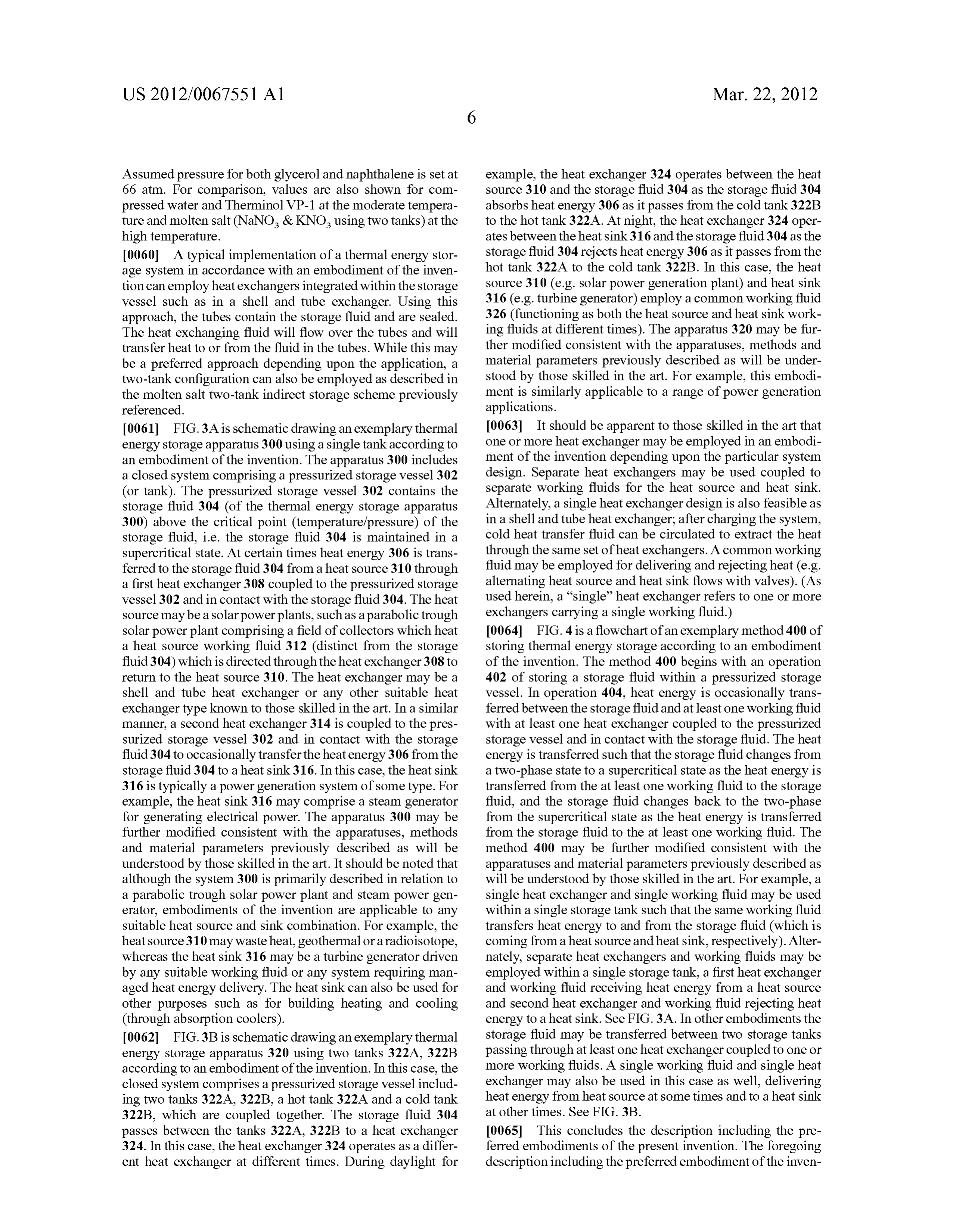
Assumed pressure for both glycerol and naphthalene is set at example, the heat exchanger 324 operates between the heat 66 atm. For comparison, values are also shown for com source 310 and the storage fluid 304 as the storage fluid 304 pressed water and Therminol VP-1 at the moderate tempera absorbs heat energy 306 as it passes from the cold tank 322B ture and molten salt (NaNO & KNO, using two tanks) at the to the hot tank 322A. At night, the heat exchanger 324 oper high temperature. ates between the heat sink316 and the storage fluid 304 as the 0060 A typical implementation of a thermal energy stor storage fluid 304 rejects heatenergy 306 as it passes from the age system in accordance with an embodiment of the inven hot tank 322A to the cold tank 322B. In this case, the heat tion can employ heat exchangers integrated within the storage Source 310 (e.g. Solar power generation plant) and heat sink vessel Such as in a shell and tube exchanger. Using this 316 (e.g. turbine generator) employ a common working fluid approach, the tubes contain the storage fluid and are sealed. 326 (functioning as both the heat source and heat sink work The heat exchanging fluid will flow over the tubes and will ing fluids at different times). The apparatus 320 may be fur transfer heat to or from the fluid in the tubes. While this may ther modified consistent with the apparatuses, methods and be a preferred approach depending upon the application, a material parameters previously described as will be under two-tank configuration can also be employed as described in stood by those skilled in the art. For example, this embodi the molten salt two-tank indirect storage scheme previously ment is similarly applicable to a range of power generation referenced. applications.
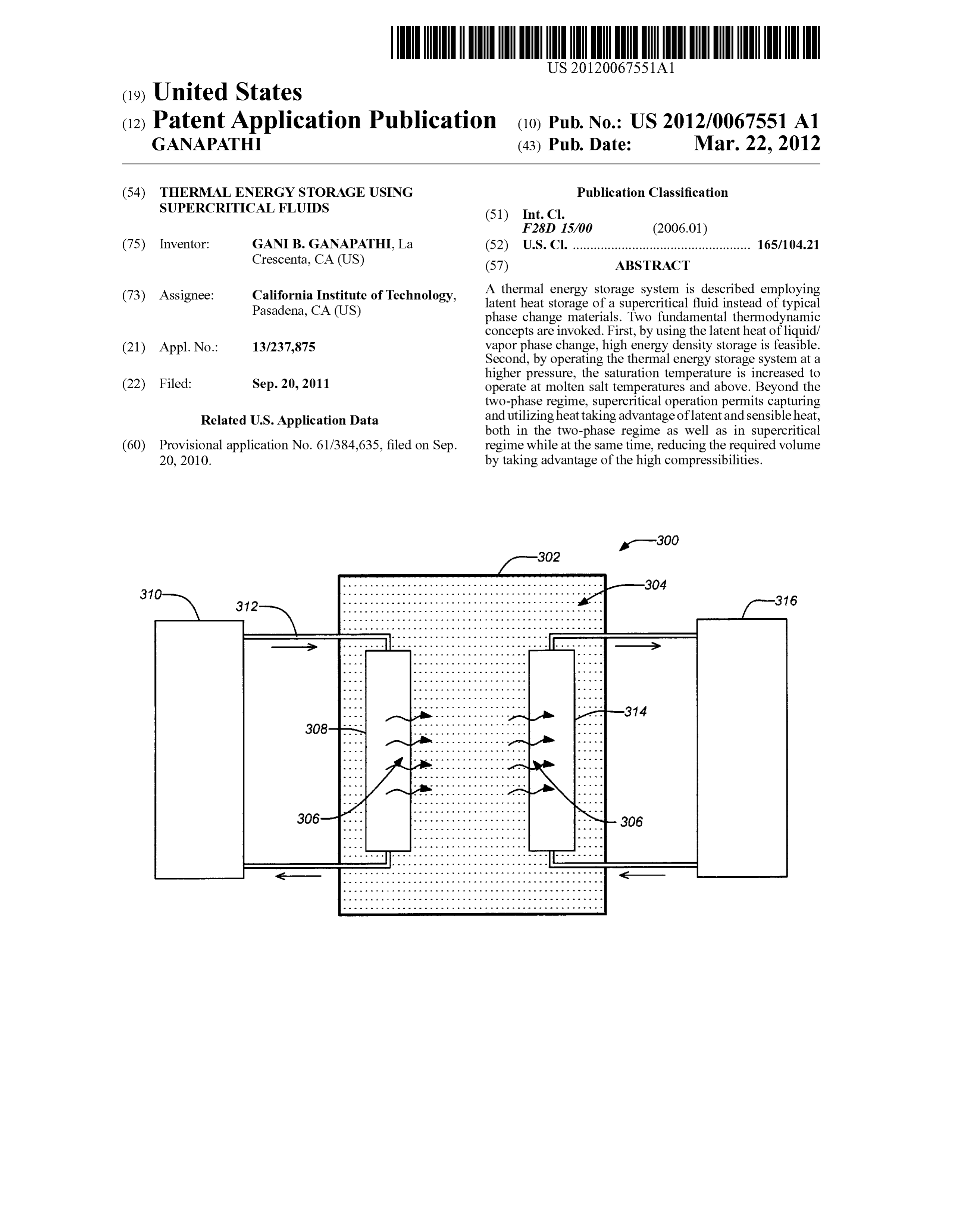
0061 FIG.3A is schematic drawing an exemplary thermal 0063. It should be apparent to those skilled in the art that energy storage apparatus 300 using a single tank according to one or more heat exchanger may be employed in an embodi an embodiment of the invention. The apparatus 300 includes ment of the invention depending upon the particular system a closed system comprising a pressurized storage vessel 302 design. Separate heat exchangers may be used coupled to (or tank). The pressurized storage vessel 302 contains the separate working fluids for the heat Source and heat sink. storage fluid 304 (of the thermal energy storage apparatus Alternately, a single heat exchanger design is also feasible as 300) above the critical point (temperature/pressure) of the in a shell and tube heat exchanger, after charging the system, storage fluid, i.e. the storage fluid 304 is maintained in a cold heat transfer fluid can be circulated to extract the heat Supercritical state. At certain times heat energy 306 is trans through the same set of heat exchangers. A common working ferred to the storage fluid 304 from a heat source 310 through fluid may be employed for delivering and rejecting heat (e.g. a first heat exchanger 308 coupled to the pressurized storage alternating heat Source and heat sink flows with valves). (AS vessel 302 and in contact with the storage fluid 304. The heat used herein, a 'single' heat exchanger refers to one or more source may be a solar powerplants, such as a parabolic trough exchangers carrying a single working fluid.) Solar power plant comprising a field of collectors which heat 0064 FIG. 4 is a flowchart of an exemplary method 400 of a heat source working fluid 312 (distinct from the storage storing thermal energy storage according to an embodiment fluid 304) which is directed through the heat exchanger 308 to of the invention. The method 400 begins with an operation return to the heat source 310. The heat exchanger may be a 402 of storing a storage fluid within a pressurized storage shell and tube heat exchanger or any other suitable heat vessel. In operation 404, heat energy is occasionally trans exchanger type known to those skilled in the art. In a similar ferred between the storage fluid and at least one working fluid manner, a second heat exchanger 314 is coupled to the pres with at least one heat exchanger coupled to the pressurized Surized storage vessel 302 and in contact with the storage storage vessel and in contact with the storage fluid. The heat fluid 304 to occasionally transfer the heatenergy 306 from the energy is transferred such that the storage fluid changes from storage fluid 304 to a heat sink316. In this case, the heat sink a two-phase state to a Supercritical state as the heat energy is 316 is typically a power generation system of some type. For transferred from the at least one working fluid to the storage example, the heat sink 316 may comprise a steam generator fluid, and the storage fluid changes back to the two-phase for generating electrical power. The apparatus 300 may be from the Supercritical state as the heat energy is transferred further modified consistent with the apparatuses, methods from the storage fluid to the at least one working fluid. The and material parameters previously described as will be method 400 may be further modified consistent with the understood by those skilled in the art. It should be noted that apparatuses and material parameters previously described as although the system 300 is primarily described in relation to will be understood by those skilled in the art. For example, a a parabolic trough solar power plant and steam power gen single heat exchanger and single working fluid may be used erator, embodiments of the invention are applicable to any within a single storage tank Such that the same working fluid Suitable heat Source and sink combination. For example, the transfers heat energy to and from the storage fluid (which is heat source 310 may waste heat, geothermal or a radioisotope, coming from a heat source and heat sink, respectively). Alter whereas the heat sink 316 may be a turbine generator driven nately, separate heat exchangers and working fluids may be by any suitable working fluid or any system requiring man employed within a single storage tank, a first heat exchanger aged heat energy delivery. The heat sink can also be used for and working fluid receiving heat energy from a heat source other purposes such as for building heating and cooling and second heat exchanger and working fluid rejecting heat (through absorption coolers). energy to a heat sink. See FIG. 3A. In other embodiments the 0062 FIG.3B is schematic drawing an exemplary thermal storage fluid may be transferred between two storage tanks energy storage apparatus 320 using two tanks 322A, 322B passing through at least one heat exchanger coupled to one or according to an embodiment of the invention. In this case, the more working fluids. A single working fluid and single heat closed system comprises a pressurized storage vessel includ exchanger may also be used in this case as well, delivering ing two tanks 322A, 322B, a hot tank 322A and a cold tank heat energy from heat Source at Some times and to a heat sink 322B, which are coupled together. The storage fluid 304 at other times. See FIG. 3B.
passes between the tanks 322A, 322B to a heat exchanger 0065. This concludes the description including the pre 324. In this case, the heat exchanger 324 operates as a differ ferred embodiments of the present invention. The foregoing ent heat exchanger at different times. During daylight for description including the preferred embodiment of the inven
Page 16
US 2012/0067551A1 Mar. 22, 2012
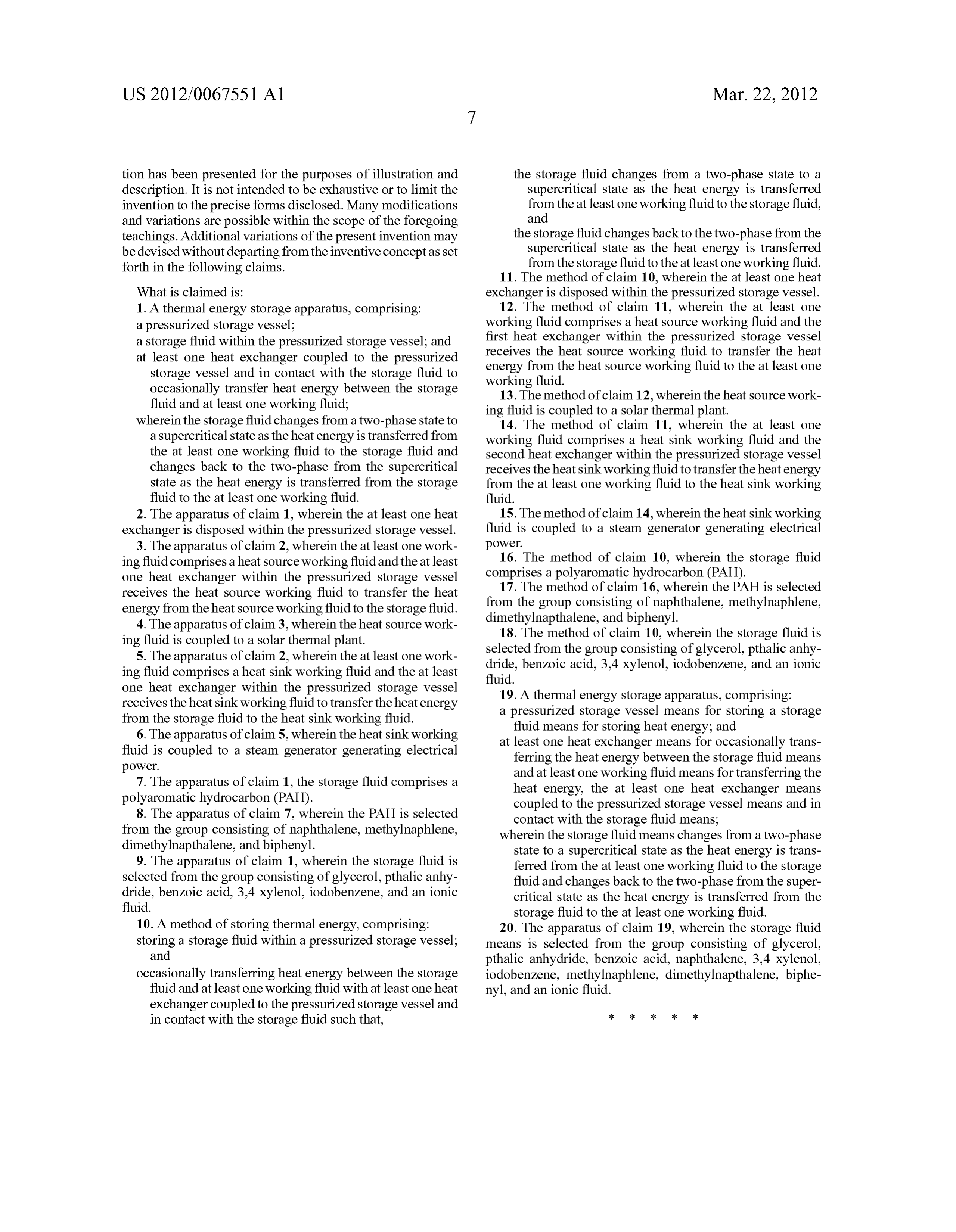
tion has been presented for the purposes of illustration and the storage fluid changes from a two-phase State to a description. It is not intended to be exhaustive or to limit the Supercritical state as the heat energy is transferred invention to the precise forms disclosed. Many modifications from the at least one working fluid to the storage fluid, and variations are possible within the scope of the foregoing and teachings. Additional variations of the present invention may the storage fluid changes back to the two-phase from the be devised without departing from the inventive concept as set Supercritical state as the heat energy is transferred forth in the following claims. from the storage fluid to the at least one working fluid. 11. The method of claim 10, wherein the at least one heat
What is claimed is: exchanger is disposed within the pressurized storage vessel. 1. A thermal energy storage apparatus, comprising: 12. The method of claim 11, wherein the at least one a pressurized storage vessel; working fluid comprises a heat source working fluid and the a storage fluid within the pressurized storage vessel; and first heat exchanger within the pressurized storage vessel at least one heat exchanger coupled to the pressurized receives the heat source working fluid to transfer the heat storage vessel and in contact with the storage fluid to energy from the heat Source working fluid to the at least one occasionally transfer heat energy between the storage working fluid.
fluid and at least one working fluid; 13. The method of claim 12, wherein the heat source work ing fluid is coupled to a Solar thermal plant.
wherein the storage fluid changes from a two-phase state to 14. The method of claim 11, wherein the at least one a Supercritical state as the heatenergy is transferred from working fluid comprises a heat sink working fluid and the the at least one working fluid to the storage fluid and second heat exchanger within the pressurized storage vessel changes back to the two-phase from the Supercritical receives the heatsink working fluid to transfer the heatenergy state as the heat energy is transferred from the storage from the at least one working fluid to the heat sink working fluid to the at least one working fluid. fluid.
2. The apparatus of claim 1, wherein the at least one heat 15. The method of claim 14, wherein the heat sink working exchanger is disposed within the pressurized storage vessel. fluid is coupled to a steam generator generating electrical 3. The apparatus of claim 2, wherein the at least one work power.
ing fluid comprises aheat Source working fluid and the at least 16. The method of claim 10, wherein the storage fluid one heat exchanger within the pressurized storage vessel comprises a polyaromatic hydrocarbon (PAH). receives the heat source working fluid to transfer the heat 17. The method of claim 16, wherein the PAH is selected energy from the heat Source working fluid to the storage fluid. from the group consisting of naphthalene, methylnaphlene, 4. The apparatus of claim3, wherein the heat source work dimethylnapthalene, and biphenyl.
ing fluid is coupled to a Solar thermal plant. 18. The method of claim 10, wherein the storage fluid is 5. The apparatus of claim 2, wherein the at least one work selected from the group consisting of glycerol, pthalic anhy ing fluid comprises a heat sink working fluid and the at least dride, benzoic acid, 3.4 xylenol, iodobenzene, and an ionic fluid.
one heat exchanger within the pressurized storage vessel 19. A thermal energy storage apparatus, comprising: receives the heat sink working fluid to transfer the heatenergy a pressurized storage vessel means for storing a storage from the storage fluid to the heat sink working fluid. fluid means for storing heat energy; and 6. The apparatus of claim 5, wherein the heat sink working at least one heat exchanger means for occasionally trans fluid is coupled to a steam generator generating electrical ferring the heat energy between the storage fluid means power.
7. The apparatus of claim 1, the storage fluid comprises a and at least one working fluid means for transferring the polyaromatic hydrocarbon (PAH). heat energy, the at least one heat exchanger means coupled to the pressurized storage vessel means and in 8. The apparatus of claim 7, wherein the PAH is selected contact with the storage fluid means; from the group consisting of naphthalene, methylnaphlene, wherein the storage fluid means changes from a two-phase dimethylnapthalene, and biphenyl. state to a Supercritical state as the heat energy is trans 9. The apparatus of claim 1, wherein the storage fluid is ferred from the at least one working fluid to the storage selected from the group consisting of glycerol, pthalic anhy fluid and changes back to the two-phase from the Super dride, benzoic acid, 3.4 xylenol, iodobenzene, and an ionic critical State as the heat energy is transferred from the fluid. storage fluid to the at least one working fluid. 10. A method of storing thermal energy, comprising: 20. The apparatus of claim 19, wherein the storage fluid storing a storage fluid within a pressurized storage vessel; means is selected from the group consisting of glycerol, and pthalic anhydride, benzoic acid, naphthalene, 3.4 xylenol, occasionally transferring heat energy between the storage iodobenzene, methylnaphlene, dimethylnapthalene, biphe fluid and at least one working fluid with at least one heat nyl, and an ionic fluid.
exchanger coupled to the pressurized storage vessel and
in contact with the storage fluid such that,
Provenance
- Collection
- Patents citing this work
- Original assignee
- California Institute of Technology
- Pages
- 16
- Method
- pdftotext (the PDF's own text layer) + pdftoppm 300dpi page scans
- Patent office record
- patents.google.com →
- Source
- Google Patents citing-documents table
- Inventors
- Gani B. Ganapathi; California Institute of Technology
- Published
- 2012-03-22
- Transcribed from
- patentimages.storage.googleapis.com →