patent · US6223558
Method of refrigeration purification and power generation of industrial waste gas and the apparatus therefor
1 May 2001
Page 1 — bibliographic record
(12) United States Patent (10) Patent No.: US 6,223,558 B1 Yi (45) Date of Patent: May 1, 2001
(54) METHOD OF REFRIGERATION 4,738,699 4/1988 Apffel ...................................... 62/11 PURIFICATION AND POWER GENERATION 5,461,870 10/1995 Paradowski .............................. 62/11
OF INDUSTRIAL WASTE GAS AND THE
APPARATUS THEREFOR
* cited by examiner (76) Inventor: Yuanming Yi, 5i Jiangwan Xin Chun,
Li Ling City, Hunan Province (CN), Primary Examiner-Corrine McDermott
ASSistant Examiner Malik N. Drake (*) Notice: Subject to any disclaimer, the term of this (74) Attorney, Agent, or Firm Jenkens & Gilchrist, P.C. patent is extended or adjusted under 35
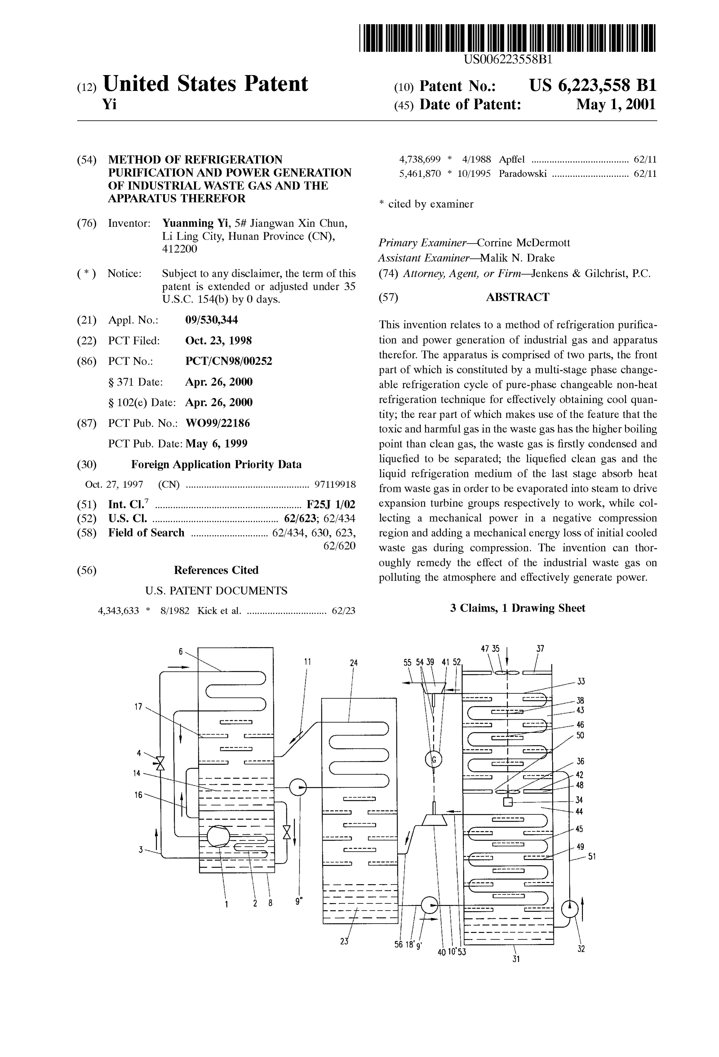
U.S.C. 154(b) by 0 days. (57) ABSTRACT (21) Appl. No.: 09/530,344 This invention relates to a method of refrigeration purifica (22) PCT Filed: Oct. 23, 1998 tion and power generation of industrial gas and apparatus (86) PCT No.: PCT/CN 98/00252 therefor. The apparatus is comprised of two parts, the front part of which is constituted by a multi-stage phase change
S371 Date: Apr. 26, 2000 able refrigeration cycle of pure-phase changeable non-heat S 102(e) Date: Apr. 26, 2000 refrigeration technique for effectively obtaining cool quan tity; the rear part of which makes use of the feature that the (87) PCT Pub. No.: WO99/22186 toxic and harmful gas in the waste gas has the higher boiling PCT Pub. Date: May 6, 1999 point than clean gas, the waste gas is firstly condensed and (30) Foreign Application Priority Data liquefied to be separated; the liquefied clean gas and the liquid refrigeration medium of the last Stage absorb heat
Oct. 27, 1997 (CN) ................................................ 971.19918 from waste gas in order to be evaporated into Steam to drive (51) Int. Cl." ..................................................... F25, 1/02 expansion turbine groups respectively to work, while col (52) U.S. Cl. ................................................. 62/623; 62/434 lecting a mechanical power in a negative compression (58) Field of Search .............................. 62/434, 630, 623, region and adding a mechanical energy loss of initial cooled 62/620 waste gas during compression. The invention can thor (56) References Cited oughly remedy the effect of the industrial waste gas on polluting the atmosphere and effectively generate power.
4,343,633 * 8/1982 Kicket al. ............................... 62/23 3 Claims, 1 Drawing Sheet
Page 2
Drawing sheet — no readable text.
Page 3
METHOD OF REFRGERATION down and depressurized after turbining and enters into PURIFICATION AND POWER GENERATION condensing Space at the end of last Stage refrigeration cycle OF INDUSTRIAL WASTE GAS AND THE to be reliquefied; At the same time, with the use of the fully APPARATUS THEREFOR liquefied clean gas in the industrial waste gas as medium, it absorbs heat from hot waste gas continuously entering into
INVENTION BACKGROUND high temperature Stage and evaporates into high-pressure Steam to drive expansion turbine for electric power
The present invention relates to the environmental pro generation, the high-pressure clean gas are depressurized, tection and electric power industry, especially to the method cooled down and discharged freely after passing the expan and the apparatus of deep refrigeration purification of indus Sion turbine; At the same time, the initial cooled industrial trial waste gas, in particular the furnace flue gas, and electric waste gas flow after rapid heat eXchanged with deep refrig power generation with utilizing heat energy work of the erating clean gas is being mechanically compressed to Waste gas. increase its density and temperature for providing heat in Waste gas discharged in modern industrial production rapid evaporation of the refrigeration medium of the last Seriously pollutes the atmosphere. Toxic and harmful gas 15 Stage into high-temperature Saturated Steam; At the same eous constituents in the waste gas threaten human Survival. time, with the use of the pressure difference between a Apparently, worldwide environmental protection is very negative preSSure generated in rapid cooling of hot industrial important and the conventional technical Solutions for Solv waste gas flow after being introduced into rear part and the ing the industrial waste gas pollution are only limited to the normal preSSure of the hot industrial waste gas flow before methods of Smoke prevention, dust control and Simple being introduced into rear part, and with the use of a work deSulphurization or the like to abate pollution. Up to now, energy formed between the pressure difference and hot mostly all of the industrial furnace waste gas is discharged industrial waste gas flow, a mechanical motion is generated to the atmospheric Space relying in the manner that the via wind turbine for the kinetic energy complement in the pollutants are directly discharged into atmospheric layer by process of mechanical compression of the initial cooled adopting chimneys. 25 industrial waste gas flow.
A apparatus of refrigeration purification and power gen
OBJECT OF THE INVENTION
eration of industrial waste gas, wherein a front part of which
The object of the invention is to provide a new method is comprised of double Stages or above multi-stage refrig and the apparatus of refrigeration purification and power eration cycle of the pure-phase changeable non-heating generation of industrial waste gas. It adopts pure-phase refrigeration technique, high efficiency deep cool quantity changeable non-heating refrigeration technique for obtain being prepared by the apparatus of the pure-phase change ing high efficiency deep cool quantity, and makes use of able non-heating refrigeration; A rear part of which is deep cool quantity to liquefying toxic and harmful constitu comprised of a rear insulating pressure vessel, a medium ents in the waste gas firstly to Separate clean gas from toxic 35 pump, heat eXchangerS mounted in the rear insulating pres and harmful constituents, to thoroughly purify the industrial Sure vessel as Same as those in the last Stage refrigeration waste gas, and makes use of the heat energy of the industrial cycles of the front part, motor, a axial flow wind turbine, a waste gas to generate electric power. centrifugal air compressor, dust and Smoke collectors and liquid waste gas collectors, and expansion turbine groups
BRIEF OF INVENTION and a electric power generator group; A isolation layer is 40 provided in the mid of Said rear insulating pressure vessel
The technical Solution according to the invention as where the upper Side of the isolator layer is a negative follows: preSSure cooling region and the lower Side of the isolator A method of refrigeration purification and power genera layer is a pressurized cooling region; Said heat eXchangers tion of industrial waste gas wherein a front part is comprised are respectively installed inside the negative pressure cool of double Stages or above multi-stage refrigeration cycle of 45 ing region and the pressurized cooling region, the motor the pure-phase changeable non-heating refrigeration being transmission-linked to the centrifugal air compressor technique, high efficiency deep cool quantity being prepared and the axial flow wind turbine via coupling shaft, Said axial by the method of the pure-phase changeable non-heating flow wind turbine is installed in an inlet of the negative refrigeration; Hot waste gas introduced into a rear part is preSSure-cooling region and a first dust and Smoke collector progressively cooled by Stages with the use of the deep cool 50 is further mounted at the inlet, hot industrial waste gas being quantity, with the use of the feature that the liquefying introduced into the rear part insulating pressure vessel to boiling temperatures of the toxic and harmful constituents in drive blades of the axial flow wind turbine for centrifugal the waste gas are all higher than the boiling temperature of Separating the dust and Smoke which is initially collected; the clean oxygen and nitrogen, the waste gas is firstly Said centrifugal air compressor is installed on the isolation liquefied by Stages in its corresponding boiling temperature 55 layer, namely, mounted on an inlet of the pressurized cooling region in the respectively refrigerating Stairs to completely region, a Second dust and Smoke collector being further Separate with the clean gas and then respectively be col mounted at the inlet, dust and Smoke being centrifugal lected as raw material; At the same time, with the use of the Separated and collected again; Said liquid waste gas collec last Stage phase change in the method of the last Stage of the tors are respectively provided in the interspace of the heat pure-phase changeable non-heating refrigeration technique 60 eXchangers inside the negative pressure cooling region and to cool a refrigeration medium in the refrigeration cycle, the the pressurized cooling region So that the condensed and refrigeration medium, on one hand, releases Sensible cool liquefied toxic and harmful constituents are respectively and latent cool to final liquefy the clean gaseous constituents collected as raw material where oxygen and nitrogen con in the industrial waste gas and, on the other Side, absorbs Stituents in the waste gas are finally condensed as liquid and heat thereon and is evaporated into high-temperature Satu 65 Stored at the bottom of the pressurized cooling region of rear rated Steam to drive expansion turbine for power generation, part insulating pressure vessel; Said medium pump is con and then the refrigeration medium of the last Stage is cooled nected to an inlet pipe of the heat eXchanger in the negative
Page 4
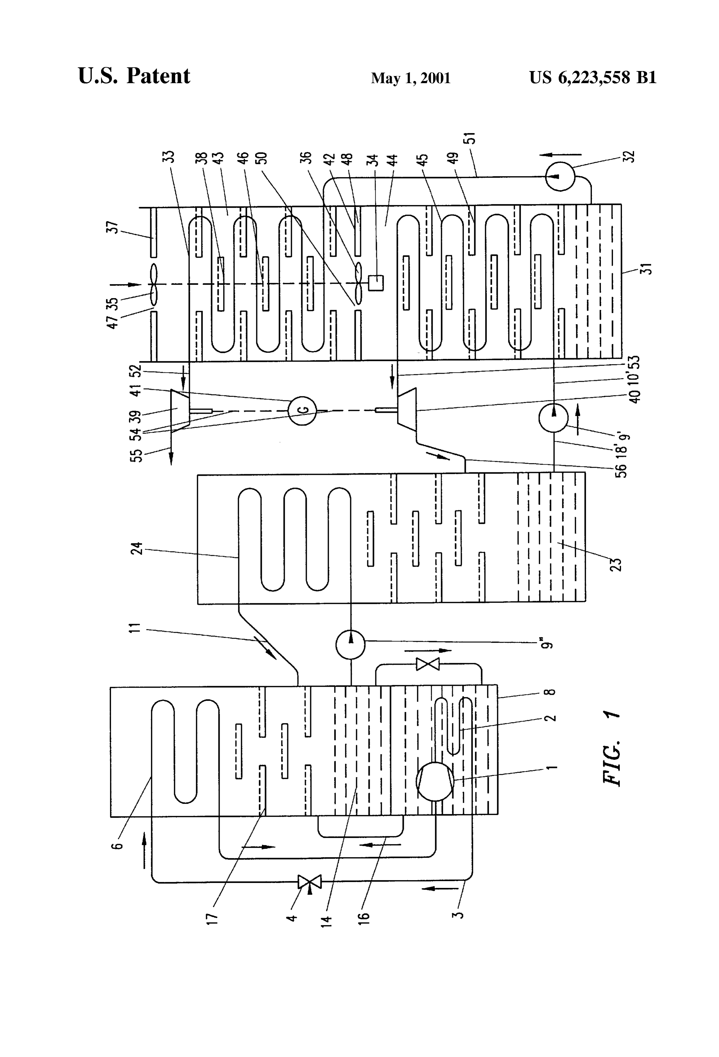
preSSure-cooling region via a first insulating preSSure pipe, perature of the evaporator 6 and condensing temperature of an outlet pipe of the heat eXchanger in the negative pressure condenser is So Small that the first stage refrigeration can cooling region being connected to the first expansion turbine have higher refrigerating efficiency in refrigeration and group via a Second insulating pressure pipe, an inlet pipe of refrigeration Supply. Steam generated by the heat dissipated the heat eXchanger in the preSSurized cooling region being 5 in the refrigerating compressor 1 and the condenser 2 passes connected to medium pump in the front part last Stage of through vent pipe 16 and enters into the condensing Space refrigeration cycle Via a medium delivery pipe, an outlet comprised of Super-cooled medium condensing plates 17 pipe of the heat eXchanger in the pressurized cooling region and evaporator 6 as Super-cooled liquid medium. A medium being connected to the Second expansion turbine group via pump '9" pumps the liquid refrigeration medium 14 into a an insulating return pipe, Said first and Second expansion intermediate Stage evaporator 24 to permit it to absorb heat turbine groups are respectively linked to the electric power from the return Steam of the intermediate Stage refrigeration generator group via coupling shafts, another end of the first cycle and evaporate. The evaporated refrigeration medium is expansion turbine group being a clean gas outlet where an returned to condensing Space inside the first insulating another end of the Second expansion turbine group being preSSure vessel 8 via insulating returnpipe 11 and condensed connected to refrigerating Space in the front part last Stage of 15 into Super liquid medium and cycling use when cooling. refrigeration cycle via a Second insulating return pipe. A rear part is comprised of a rear insulating preSSure The present invention is that industrial waste gas is vessel 31, a medium pump 32, heat exchangers 33, 45 introduced into the Said apparatus and progressively cooled mounted in the rear insulating pressure vessel 31, a motor by Stages into deep refrigeration low temperature So that the 34, a axial flow wind turbine 35, a centrifugal air compressor toxic and harmful constituents in the industrial waste gas are 36, dust and smoke collectors 37, 48 and liquid waste gas respectively condensed into liquid in the corresponding collectors 38, 49, and expansion turbine groups 39, 40 and temperature region. The toxic and harmful liquefied waste an electric power generator group 41.
gas constituents collected therein are used as chemical raw A isolation layer 42 is provided in the mid of the rear material and the remainders in the waste gas are the clean insulating pressure vessel 31 where the upper side of the gases Such as oxygen and nitrogen that can be condensed 25 isolator layer 42 is a negative preSSure cooling region 43 and and liquefied at last. Hence, the waste gas is thoroughly the lower Side of the isolator layer 42 is a pressurized purified. The industrial waste gas in the cooling-condensing cooling region 44. The heat eXchangers 33, 45 are respec process with the use of the deep refrigeration return tech tively installed inside the negative preSSure cooling region nology to repeatedly use the cool quantity. 43 and the pressurized cooling region 44. The motor 34 is The apparatus according to present invention not only transmission-linked to the centrifugal air compressor 36 and makes use of the work energy carried by hot industrial waste the axial flow wind turbine 35 via coupling shafts 46. gas between normal temperature and high temperature to The axial flow wind turbine 35 is installed in an inlet 47 generate electric power but further makes use of work of the negative pressure-cooling region 43 and a first dust energy thereof between low temperature to normal tempera 35 and Smoke collector 37 is further mounted at the inlet 47. ture to generate electric power. Thus, it has a high heat Hot industrial waste gas is introduced into the rear part engine efficiency. The present invention utilizes the utmost insulating preSSure vessel 31 and drives blades of the axial decreased temperature difference between evaporating tem flow wind turbine 35 to centrifugal separate the dust and perature of the evaporator and condensing environmental Smoke which is initially collected.
temperature of condenser in the Steam compression refrig 40 The centrifugal air compressor 36 is installed on the eration cycle to permit the first stage of refrigeration cycle isolation layer 42, namely, mounted on an inlet 50 of the to provide for deep refrigeration up to higher cool quantity. preSSurized cooling region 44. A Second dust and Smoke At the same time, adopting the new refrigeration cycle collector 48 is further mounted at the inlet 50. Dust and technology of multi-stage pure phase change to cool So as to Smoke is centrifugal Separated and collected again. provide enough deep cool quantity for deep refrigeration 45 The liquid waste gas collectors 38, 49 are respectively purification of industrial waste gas, in particular the furnace provided in the interspace of the heat exchangers 33, 45 flue gas, and electric power generation. inside the negative pressure cooling region 43 and the BRIEF DESCRIPTION OF DRAWING preSSurized cooling region 44. The liquid waste gas collec tors 38, 49 are two or more layerS alternating-arranged liquid
The present invention will be described hereinafter in 50 waste gas collecting plates So that the condensed and liq detail with reference to the accompanying drawing. uefied toxic and harmful constituents are respectively col EMBODIMENT DESCRIPTION lected as raw material where clean gaseous Oxygen and nitrogen constituents in the waste gas are finally condensed
FIG. 1 shows a schematic diagram of the method of as liquid and Stored at the bottom of the pressurized cooling refrigeration purification and power generation of industrial 55 region 44 of rear part insulating pressure vessel 31. waste gas and the apparatus thereof. The medium pump 32 is connected to an inlet pipe of the Referring to FIG. 1, in a first insulating pressure vessel 8 heat eXchanger 33 in the negative preSSure-cooling region 43 of the front part of the pure-phase changeable non-heating via a first insulating pressure pipe 51. An outlet pipe of the refrigeration apparatus, a refrigerating compressor 1, a con heat eXchanger 33 in the negative preSSure-cooling region 43 denser 2, a flow regulator 4 and a evaporator 6 are mounted, 60 is connected to the first expansion turbine group 39 via a hence comprise an first Stage of Steam compression refrig Second insulating preSSure pipe 52. The first expansion eration cycle. Since the refrigerating compreSSor 1 and the turbine group 39 is a high-pressure expansion turbine group. condenser 2 are immersed in liquid refrigeration medium 14, An inlet pipe of the heat eXchanger 45 in the pressurized their heat generated will be dissipated as the evaporation cooling region 44 is connected to medium pump 9" in the latent heat of the liquid refrigeration medium 14 during 65 front part last Stage of refrigeration cycle Via a medium evaporation after the first Stage refrigeration cycle is initial delivery pipe10'. An outlet pipe of the heat exchanger 45 in ized. The temperature different between evaporating tem the pressurized cooling region 44 is connected to the Second
Page 5
S 6 expansion turbine group 40 via an insulating return pipe 53. the axial flow wind turbine 35, the carried dust and Smoke The Second expansion turbine group 40 is a low-pressure is thrown into the first dust and Smoker collector 37 by the expansion turbine group. action of centrifugal force. The toxic and harmful constitu The first expansion turbine group 39 and Second expan ents in waste gas are cooled by heat eXchanger 33 and Sion turbine group 40 are respectively linked to the electric respectively condensed in its corresponding boiling tem power generator group 41 via coupling Shafts 54. Another perature region into liquid State. They are collected by liquid end of the first expansion turbine group 39 is a clean gas waste gas collector 38 and then concentrated and discharged outlet 55 where an another end of the second expansion as chemical raw materials.
turbine group 40 is connected to refrigerating Space in the The industrial waste gas in the negative pressure cooling front part last Stage of refrigeration cycle Via a Second region inside rear part insulating pressure vessel 31 has been insulating return pipe 56. cooled and the pressure is decreased, Suitable preSSure and During the operation of the present invention, the medium temperature increase with the use of the centrifugal air pump 9" is initialized. The liquid refrigeration medium 23 is compressor 36. On one side, the flow rate of waste gas permitted to enter into heat eXchanger 45 in the pressurized 15 entering the axial flow wind turbine 35 is increased. On the cooling region 44 inside the rear part insulating pressure other Side, the density and temperature of the waste gas vessel 31 via Suction liquid pipe 18", medium pump 9' and inside the pressurized cooling region 44 of the rear part medium delivery pipe10' such that the liquid refrigeration insulating pressure vessel 31 is increased. This facilitates the medium 23 absorbs heat from the entering waste gas and rapid absorption and evaporation of the liquid refrigeration evaporate to form high pressure Steam. It then enters into the medium 23 via heat eXchanger 45 to form as preSSure Steam. Second expansion turbine group 40 via the first insulating At the same time, the liquefying Speeds of the non-harmful return pipe 53 to turbine and form low pressure, low constituents waste gas in the pressurized cooling region 44 temperature Steam. It then returns back to refrigerating Space inside the rear part insulating pressure vessel 31 is greatly inside the front part last Stage refrigeration cycle via the increased.
Second return pipe 56 and is condensed as liquid refrigera 25 When the industrial waste gas was entering the centrifugal tion medium 23. air compressor 36, the remaindering dust and Smoke in In the first Stage of Steam compression refrigeration cycle, waste gas is thrown into the Second dust and Smoker which comprised of the refrigerating compressor 1, the collector 48 by the action of centrifugal force and then condenser 2, the flow regulator 4 and the evaporator 6, a concentrated and discharged.
refrigeration medium is introduced. The boiling point of The high preSSure Steam enters the first expansion turbine refrigeration medium with those of liquid refrigerating group 39 via the Second insulating pressure pipe 52 to media 14, 23 is progressively increased according to its turbine-actuate and drive electric power generator 41 to connecting Sequences. The evaporation temperature of liq generate electrical via coupling shaft 54. uid refrigeration medium 23 inside the rear part insulating In order to increase the density and flow rate of the waste preSSure vessel 31 is below deep refrigerating temperature. 35 gas inside the pressurized cooling region 44, the motor 44 AS the deep refrigerating, low temperature cool quantity and the centrifugal air compressor 36 are provided on the is generated in the heat eXchanger 45 inside the rear part intermediate isolation layer 42 of the rear part insulating insulating pressure vessel 31, negative pressure region preSSure vessel 31 to Suitably pressurize the waste gas flow. occurs inside the rear part insulating pressure vessel 31 So The energy dissipated is partly Supplemented by the motion that the industrial waste gas flow is naturally entered the rear 40 generated in the axial flow wind turbine 35 and partly part insulating pressure vessel 31. Motor 34 is initialized to Supplemented by electricity. From this, the waste gas flow permit the centrifugal air compressor 36 to mechanically initially cooled in the negative pressure-cooling region is compress the waste gas. The waste gas constituents are preSSurized while its temperature rise is further produced, completely condensed and liquefied. The firstly liquefied this newly added energy makes the expansion turbine group toxic and harmful constituents are collected by liquid waste 45 generate more electric power.
gas collector 38. The non-toxic and non-harmful constitu The apparatus manufactured according to the present ents oxygen and nitrogen constituents in the waste gas are as invention is compact and can be fixedly mounted at the arena deep refrigerating liquid Stored at the bottom of the pres of discharging industrial waste gas. It can also be manufac Surized cooling region 44 of rear part insulating pressure tured as portable apparatus that is easy transferable. It is vessel 31. 50 Supplementary used for the areas producing industrial waste The medium pump is initialized, clean gas, comprising gas Such as industrial furnaces, kiln furnaces, chemicals oxygen and nitrogen constituents in the deep refrigeration production Station, and alike to thoroughly remedy the effect Status, is pumped into the heat eXchanger 33 inside the of industrial waste gas for the atmospheric layer pollution, negative pressure cooling region 43 via the first insulating high effectively develop and utilize the heat in the industrial preSSure pipe 51 So as to absorb heat from hot waste gas and 55 waste gas for electric power generation. rapidly evaporated into high pressure Steam. It then enters What is claimed is:
the first expansion turbine group 39 via the Second insulating 1. A method of refrigeration purification and power gen preSSure pipe 52 to become normal temperature and eration of industrial waste gas wherein a front part is preSSure, non-toxic and non-harmful clean gas which is comprised of double Stages or above multi-stage refrigera freely discharged. 60 tion cycle of the pure-phase changeable non-heating refrig AS the heat eXchanger 33 inside the rear part insulating eration technique, high efficiency deep cool quantity being preSSure vessel 31 refrigerates and absorbs heat, negative prepared by the method of the pure-phase changeable non preSSure region occurs in the upper part of the rear part heating refrigeration, characterizing in that, hot waste gas insulating pressure vessel 31. When hot waste gas passes introduced into a rear part is progressively cooled by Stages through the axial flow wind turbine 35, this generates motion 65 with the use of the deep cool quantity, with the use of the that is transmitted to drive the centrifugal air compressor 36 feature that the liquefying boiling temperatures of the toxic via coupling shaft 46. When hot waste gas passes through and harmful constituents in the waste gas are all higher than
Page 6
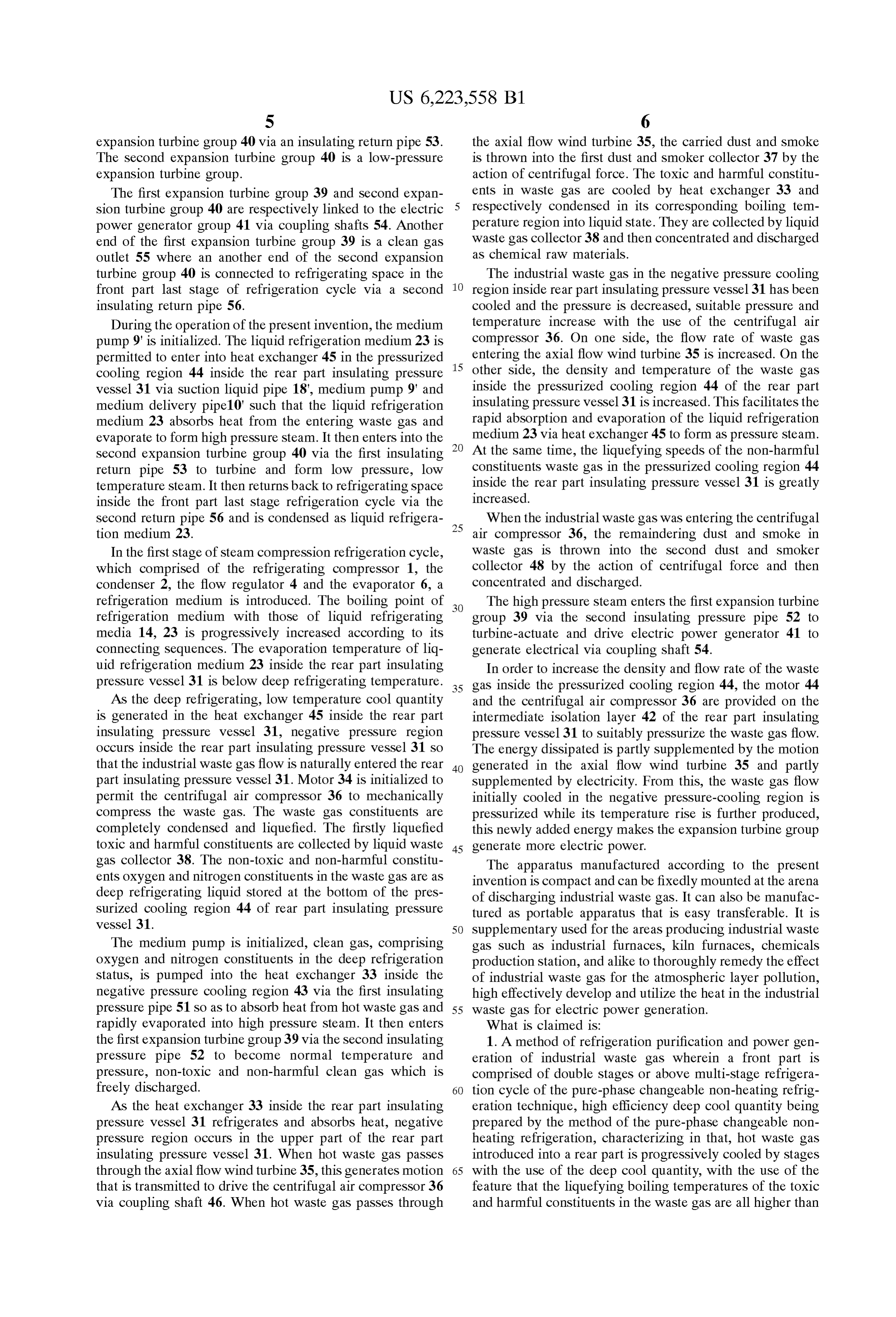
the boiling temperature of the clean oxygen and nitrogen, the turbine groups and a electric power generator group; A waste gas is firstly liquefied by Stages in its corresponding isolation layer is provided in the mid of Said rear insulating boiling temperature region in the respectively refrigerating preSSure vessel where the upper Side of the isolator layer is Stairs to completely Separate with the clean gas and then a negative preSSure cooling region and the lower Side of the respectively be collected as raw material; At the same time, isolator layer is a pressurized cooling region; Said heat with the use of the last Stage phase change in the method of eXchangers are respectively installed inside the negative the last Stage of the pure-phase changeable non-heating preSSure cooling region and the pressurized cooling region, refrigeration technique to cool a refrigeration medium in the the motor being transmission-linked to the centrifugal air refrigeration cycle, the refrigeration medium, on one hand, compressor and the axial flow wind turbine Via coupling releases Sensible cool and latent cool to final liquefy the shaft; Said axial flow wind turbine is installed in an inlet of clean gaseous constituents in the industrial waste gas and, on the negative pressure-cooling region and a first dust and the other side, absorbs heat thereon and is evaporated into Smoke collector is further mounted at the inlet, hot industrial high-temperature Saturated Steam to drive expansion turbine waste gas being introduced into the rear part insulating for power generation, and then the refrigeration medium of pressure vessel to drive blades of the axial flow wind turbine the last Stage is cooled down and depressurized after tur 15 for centrifugal Separating the dust and Smoke which is bining and enters into condensing Space at the end of last initially collected; Said centrifugal air compressor is Stage refrigeration cycle to be reliquefied; At the same time, installed on the isolation layer, namely, mounted on an inlet with the use of the fully liquefied clean gas in the industrial of the pressurized cooling region, a Second dust and Smoke waste gas as medium, it absorbs heat from hot waste gas collector being further mounted at the inlet, dust and Smoke continuously entering into high temperature Stage and being centrifugal Separated and collected again; Said liquid evaporates into high-pressure Steam to drive expansion waste gas collectors are respectively provided in the inter turbine for electric power generation, the high-pressure Space of the heat eXchangers inside the negative preSSure clean gas are depressurized, cooled down and discharged cooling region and the pressurized cooling region So that the freely after passing the expansion turbine; At the same time, condensed and liquefied toxic and harmful constituents are the initial cooled industrial waste gas flow after rapid heat 25 respectively collected as raw material where oxygen and eXchanged with deep refrigerating clean gas is being nitrogen constituents in the waste gas are finally condensed mechanically compressed to increase its density and tem as liquid and Stored at the bottom of the pressurized cooling perature for providing heat in rapid evaporation of the region of rear part insulating pressure vessel, Said medium refrigeration medium of the last Stage into high-temperature pump is connected to an inlet pipe of the heat eXchanger in Saturated Steam; At the same time, with the use of the the negative preSSure-cooling region via a first insulating preSSure difference between a negative pressure generated in preSSure pipe, an outlet pipe of the heat eXchanger in the rapid cooling of hot industrial waste gas flow after being negative pressure-cooling region being connected to the first introduced into rear part and the normal pressure of the hot expansion turbine group Via a Second insulating preSSure industrial waste gas flow before being introduced into rear pipe, an inlet pipe of the heat eXchanger in the pressurized part, and with the use of a work energy formed between the 35 cooling region being connected to medium pump in the front preSSure difference and hot industrial waste gas flow, a part last Stage of refrigeration cycle Via a medium delivery mechanical motion is generated via wind turbine for the pipe, an outlet pipe of the heat eXchanger in the pressurized kinetic energy complement in the process of mechanical cooling region being connected to the Second expansion compression of the initial cooled industrial waste gas flow. turbine group via an insulating return pipe, Said first and 2. A apparatus of refrigeration purification and power 40 Second expansion turbine groups are respectively linked to generation of industrial waste gas, wherein a front part of the electric power generator group Via coupling shafts, which is comprised of double Stages or above multi-stage another end of the first expansion turbine group being a refrigeration cycle of the pure-phase changeable non clean gas outlet where an another end of the Second expan heating refrigeration technique, high efficiency deep cool Sion turbine group being connected to refrigerating Space in quantity being prepared by the apparatus of the pure-phase 45 the front part last Stage of refrigeration cycle Via a Second changeable non-heating refrigeration, characterizing in that, insulating return pipe.
a rear part of which is comprised of a rear insulating pressure 3. A apparatus of refrigeration purification and power vessel, a medium pump, heat eXchangerS mounted in the rear generation of industrial waste gas as claim 2 characterizing insulating pressure vessel as Same as those in the last Stage in that the liquid waste gas collectors are two or more layers refrigeration cycles of the front part, motor, a axial flow 50 alternating-arranged liquid waste gas collecting plates. wind turbine, a centrifugal air compressor, dust and Smoke collectors and liquid waste gas collectors, and expansion k k k k k
Page 7
UNITED STATES PATENT AND TRADEMARK OFFICE
CERTIFICATE OF CORRECTION
PATENT NO. : 6,223,558 B. Page 1 of 2
INVENTOR(S) : Yuanming Yi
It is certified that error appears in the above-identified patent and that said Letters Patent is hereby corrected as shown below:
Column 1
Line 49, after "refrigeration;" start new paragraph Line 58, after "material;" start new paragraph Column 2
Line 3, after "relinquefied;" start new paragraph Line 10, after "turbine;" start new paragraph Line 15, after "steam:" start new paragraph Line 18, delete "gas"
Line 32, after "refrigeration;" start new paragraph Line 39, after "group" start new paragraph Line 58, after "again;" start new paragraph Line 66, after "vessel;" start new paragraph Column 4
Column 5
Line 17, replace "pipe 10'" with -- pipe 10'-- Column 7
Line 5, after "material;" start new paragraph Line 17, after "reliquefied;" start new paragraph Line 24, after "turbine;" start new paragraph Line 30, after "steam;" start new paragraph Column 8,
Line 1, after "group;" start new paragraph Line 1, replace "A" with -- a--
Line 5, after "region" start new paragraph Line 5, replace "Said" with -- said -- Line 10, after "shaft;" start new paragraph Line 10, replace "Said" with -- said -- Line 16, after "collected;" start new paragraph Line 16, replace "Said" with -- said -- Line 20, after "again;" start new paragraph
Page 8
UNITED STATES PATENT AND TRADEMARK OFFICE
CERTIFICATE OF CORRECTION
PATENT NO. : 6,223,558 Bl Page 2 of 2
INVENTOR(S) : Yuanming Yi
It is certified that error appears in the above-identified patent and that said Letters Patent is hereby corrected as shown below:
Column 8 contd.
Line 28, after "vessel;" start new paragraph Line 28, replace "Said" with -- said -- Line 39, after "pipe" start new paragraph Line 39, replace "Said" with -- said -- Signed and Sealed this
Fifth Day of March, 2002
Attest:
JAMES E. ROGAN
Attesting Officer Director of the United States Patent and Trademark Office
Provenance
- Collection
- Cited prior art
- Original PDF
- patentimages.storage.googleapis.com →
- Filed
- 1998-10-23
- Pages
- 8
- Method
- pdftotext (the PDF's own text layer) + pdftoppm 300dpi page scans
- Source
- Google Patents bibliographic record
- Granted
- 2001-05-01
- Inventors
- Yuanming Yi
- Transcribed from
- patentimages.storage.googleapis.com →