patent · US3242911
Apparatus and method for operating a vapor generator at subcritical and supercritical pressures
29 March 1966
Page 1
March 29, 1966 W. W. SCHROEDTER 3,242,911
APPARATUS AND METHOD FOR OPERATING AWAPOR
GENERATOR AT SUBCRITICAL AND
SUPERCRITICAL PRESSURES
SUPER.
EANG
ZONE
RAOANT
HEATING
SEPA
RAN G
MXNG
ZONE
PRE
HEANG
ZONE
INVENTOR.
WLLBURT W. SCHROEDTER
FIG.
AGENT
Page 2
United States Patent Office 3,242,911 Patented Mar. 29, 1966
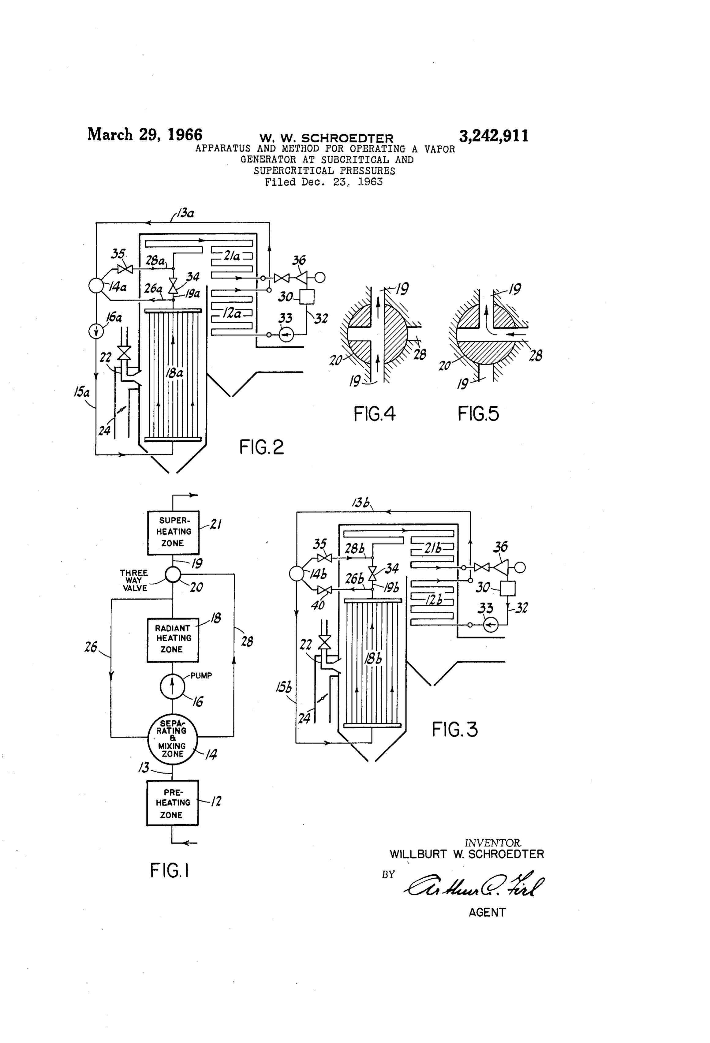
pressure, which generator when at subcritical pressure will 3,242,911 operate as a natural circulation vapor generator; APPARATUS AND METHOD FOR OPERATENG A FIG. 4 is a diagrammatic representation of a three WAPOR GENERATOR AT SUBCRTICAL AND way valve when in the position for supercritical opera SUPERCRTCAL PRESSURES tion; and
Wilburt W. Schroedter, West Hartford, Conn., assignor FIG. 5 when in the position for subcritical operation. to Cornbustion Engineering, Inc., Windsor, Corr., a Referring now to the drawing wherein like reference corporation of Delaware characters are used throughout to designate like elements, Filed Dec. 23, 1963, Ser. No. 332,684 the illustrative embodiment of the invention depicted in
10 FIG. 1 includes a vapor generator designated generally
The invention relates generally to vapor generators as 10, and comprising in the flow path of the working operating at normal load in the Supercritical pressure medium a preheating zone 12, a conduit 13, a separating range, and is particularly concerned with a method and and mixing zone 14, a conduit 15, a recirculating pump apparatus of operating such generators in the subcritical 16, a radiant heating zone 18, a conduit 9, a three-Way pressure range at lower loads than maximum load. valve 20 and a superheating zone 21. Fuel and air for The critical temperature of a gas is generally defined burning is discharged into the vapor generator by Way as the temperature at which the gas may just be liquified of burner 22 and air duct 24, respectively. at its critical pressure. For water or water vapor this When operating the vapor generator at Supercritical pressure is 3206.3 p.s.i.a. (pounds. per square inch ab pressure and with a modified once-through flow pattern a solute) at the critical temperature of 705.34 F. When 20 through-flow quantity of the working fluid passes through heating water at a pressure below the critical pressure it the preheating zone 2 into the separating and mixing passes from the liquid state to the vapor state at a constant zone 14. In this zone a relatively small recirculated por temperature the so-called saturation temperature. A cer tion of the working fluid having been returned from the tain amount of heat is required to change the water outlet of the radiant heating zone 18 by way of conduit from the liquid state to the vapor state. This heat quan 25 26 is mixed with the through-flow quantity to form a tity is called heat of evaporation. It decreases with an total quantity. This total quantity then passes through increase in pressure and becomes Zero at the critical the radiant heating zone 18, with the through-flow quan pressure. When heating water at the critical pressure or tity continuing through conduit 19 and three-way valve at a supercritical pressure with zero heat of evaporation 20 into superheating zone 21, while the above-mentioned a single phase condition therefore prevails, with the 30 recirculated portion by means of pump 16 and conduit temperature constantly increasing while heat is added. 26 is returned to the separating and mixing Zone 14. When heating water at subcritical pressure to a two-phase When operating at supercritical pressure as above de condition prevails, with the temperature rising to the scribed the three-way valve 20 occupies the position shown evaporation point, remaining constant until all water is 35 in FIG. 4 with the through-flow quantity passing there evaporated to steam, and then rising again in the process through in the direction indicated by the arrow. of superheating the steam. When operating the vapor generator at subcritical pres A number of important advantages are being derived sure such as at low loads, and with a controlled circula from operating a supercritical vapor generator at re tion flow pattern the through-flow quantity of the working duced pressure during low load operation. fluid passes through the preheating Zone 2 into the These advantages include a considerable reduction in 40 separating and mixing zone 14, wherein it is mixed with feed pump power, and a marked reduction in super a relatively large recirculated portion returned from the heater tube stress. The latter advantage may be ex outlet of the radiant heating zone i8 by way of conduit pressed in one of two ways for a given superheater 26. The total quantity then passes through the radiant material selection: (1) as an extension of the load range heating zone i8 for the generation of steam at constant over which superheater outlet steam temperature may be 45 temperature. The resultant mixture of steam and water is maintained at its rated full load value or, (2) as an in then returned to the separating and mixing Zone 14 where crease in the expected life of a Superheater tube resulting in apparatus is provided for separating the steam from from the lowered stress level. the water. The water again then passes through the It is accordingly an object of the invention to increase 50 radiant heating zone 18 and the steam flows to the the over-all economy of operating a supercritical vapor superheater zone 21 via conduit 28, three-way valve 20 generator at lower loads by reducing the operating pres and the downstream portion of conduit 19. When op sure at such loads to a pressure within the subcritical erating at subcritical pressure as hereinabove described pressure range. valve 20 occupies the position shown in FIG. 5 with the A further object of the invention is to accomplish the through-flow quantity passing therethrough in the direc above with a minimum of capital investment for addi tion indicated by the arrow.
tional apparatus such as valves, piping, separators, etc. While FIG. 1 shows the basic idea of the invention in a Other objects and advantages of the invention will simplified and diagrammatic form, FIGS. 2 and 3 illus become apparent from the following description of an trate two applications thereof in a more detailed and illustartive embodiment thereof when taken in conjunc 60 specified manner.
Thus, in the steam power plant shown in FIG. 2 feed tion with the accompanying drawings wherein: water is taken from the condenser 30 and is delivered FIG. 1 is a diagrammatic representation of a vapor under pressure into economizer 12a by way of conduit generator organized for both supercritical and subcritical 32 and feed pump 33. Economizer 2a corresponds pressure operation; to the preheating zone 12 of FIG. 1. The preheated FIG. 2 depicts a vapor generating plant including a 65 water is then delivered to drum 4a wherein the feed modified once-through vapor generator operating at sup water is mixed with a recirculated portion of the work ercritical pressure, which generator when at subcritical ing fluid returned from the furnace tubes 18.a. Drum pressure will operate as a controlled circulation vapor 14a and tubes 8a correspond to the separating and mix generator, ing Zone 14 and radiant heating zone 18 of FIG. 1, re FIG. 3 depicts a vapor generating plant including a 70 spectively.
once-through vapor generator operating at supercritical When operating at Supercritical pressure the through
Page 3
flow quantity of the working fluid is delivered directly flow steam generator when operating at top load in the from furnace tubes 8a to superheater 21a by way of supercritical pressure range. However when operating conduit 9a and valve 34. Conduit 9a and superheater in the subcritical pressure range at low loads this steam 21a correspond to conduit 19 and superheater 2 of FIG. generator is operating in the manner of a natural circu 1, respectively. A second valve 35 provided in conduit lation boiler.
28a is closed during supercritical pressure operation. In Considering first operation at full load and at super the embodiment of FIG. 2 valve 34 performs one of the critical pressure the feedwater is taken from condenser two functions of the three-way valve 20 of FIG. 1, 30, forced through economizer 12b into furnace tubes namely that of controlling the flow from radiant heating 18b by feed pump 33. These above-named elements 12b zone 18 to superheating zone 21, and valve 35 performs IO and 18b of FIG. 3 correspond to preheating zone 12 the other function, namely that of controlling the flow and radiant heating zone 18 of FIG. 1, respectively. from vessel 4a to superheater 21a. After having ab From furnace tubes 8b the heated working fluid flows di sorbed the amount of heat required for raising the steam rectly to superheater 2b by way of conduit 19b and temperature to a desired temperature level the steam at valve 34. Under these operating conditions valve 40 in supercritical pressure is conducted to one or more steam 5 conduit 26b and valve 35 in conduit 28b are closed. turbine generators 36, with the steam subsequently be From superheater 21b which corresponds to superheat ing condensed in condenser 30, thereby returning to the ing zone 21 of FIG. 1, the steam is delivered to turbine beginning of the cycle. generator 36 and condenser 30 thereby completing the The steam power plant illustrated by FIG. 2 and as steam cycle.
hereinabove described as operating in the supercritical 20 When operating the steam, generator illustrated in pressure range includes a steam generator of the modi FIG. 3 at lower loads and in the subcritical pressure fied once-through flow type also generally known as a range, the steam and water circulates and flows in the combined circulation steam generator. The feature manner of a natural circulation boiler. Accordingly, which distinguishes the combined circulation steam gen the feedwater passes from economizer 12b into drum erator from the throughflow steam generator is the 25 14b, where it is mixed with a relatively large quantity provision for recycling of a small fraction of the work of recirculated water which is returned from the outlet ing fluid from the outlet of the radiant zone 14 to the of the furnace tubes 18b. This mixture in conduit 15b inlet thereof (see conduit 26 of FIG. 1 or 26a of FIG. possesses a greater density than the density of the mix 2). This recycling of the working fluid serves the pur ture of steam and water rising in the furnace tubes 18b, pose of controllably maintaining a minimum velocity of 30 and accordingly flows to the inlet of these tubes by way the working medium passing through the furnace tubes of duct 15b. A portion of the water is evaporated to for the purpose of satisfactorily protecting these tubes, steam while passing through tubes 8b. The water and with this velocity being independent of the through-flow steam mixture thus produced is returned to drum 14b quantity dictated by steam generator load. by way of conduit 26b with valve 40 being open and When operating the combined circulation steam gen valve 34 in conduit 19b being closed. Conventional ap erator of FIG. 2 at Subcritical pressure in accordance paratus provided in drum 14b serves to separate the with the invention, the flow pattern of the working fluid steam from the water. The steam then passes through is changed to the flow pattern of a controlled steam gen conduit 28b, valve 35, through superheater 21b and to erator which requires a steam and water drum for sepa turbine 36. The water separated from the steam returns ration of the steam from the water. This is in contrast 40 to the inlet of tubes 8b by gravity. to Supercritical pressure operation when a steam and While I have illustrated and described two preferred water drum is not required. However, in a combined embodiments of my invention it is to be understood that circulation steam generator operating at supercritical such are merely illustrative and not restrictive and that pressure it is desirable to provide a mixing vessel 14 variations and modifications may be made therein with (FIG. 1), 14a (FIG. 2), for mixing the through-flow out departing from the spirit and scope of the invention. quantity with that portion of the working fluid that is I therefore do not wish to be limited to the precise details returned from the outlet of the radiant heating zone set forth but desire to avail myself of such changes 18, 18a. In accordance with the invention the mixing as fall within the purview of my invention. vessel 4a now also serves the purpose of the steam and I claim:
water drum which is required when operating the steam 50 . A once-through forced flow type vapor generator generator at a subcritical pressure. The flow path of the organized for operation alternatively at supercritical pres working fluid when operating in the subcritical pressure sure and at Subcritical pressure, the combination com range is therefore as follows: prlSing:
Feedwater flows from the condenser 30 via conduit a working fluid preheating means; 32, feed pump 33, economizer 2a and conduit 13a into a fluid separating and mixing vessel; mixing vessel or steam and water drum 4a, wherein the a working fluid radiant heating means; feedwater mixes with water returned from the outlet a working fluid superheating means; of furnace tubes 8a. This combined water quantity means for passing a through-flow quantity of the work then flows to the furnace tubes 18a by way of conduit ing fluid through said preheating means, said fluid 15a and recirculating pump 16a. While passing through 60 Separating and mixing vessel and said radiant heat furnace tubes 18a a portion of the water is evaporated ing means in the order named; to steam with the water and steam mixture being dis means for passing an additional quantity of said work charged into the steam and water drum 14a by way of ing fluid through said separating and mixing vessel conduit 26a, and with valve 34 in conduit 19a being and said radiant heating means and for returning closed. Conventional equipment is provided in steam and water drum 4.a for the separation of the steam from the Said additional quantity to said separating and mix water. An amount of steam equal to the through-flow ing vessel;
quantity then flows from vessel 14a to the superheater first conduit means for passing only a quantity of said 21a by way of conduit 28a and valve 35 which valve is Working fluid that is equal to said through flow now in the open position. Having been heated in super 70 quantity from said radiant heating means to said heater 2a to the desired steam temperature the steam Superheating means;
is then conducted to steam turbine generator 36 and is Second conduit means for passing only a quantity that subsequently condensed in condenser 30 thereby com is equal to said through flow quantity from said pleting the steam cycle. Separating and mixing vessel to said superheating In FIG. 3 the invention is applied to a straight through means;
Page 4
valve means in said first conduit means and in said a first conduit for passing only a quantity of said work second conduit means; ing fluid that is equal to said through-flow quantity a first position of said valve means whereby when op from said furnace heating surface to said Super erating at supercritical pressure said valve means heater;
a second conduit for passing only a quantity that is are opened for passage of Said through-flow quantity equal to said through-flow quantity from Said sep through said first conduit means, and are closed for arating and mixing vessel to said Superheater; preventing flow through said second conduit means valve means operatively connected to said first conduit and said fluid separating and mixing vessel can func and to said second conduit; tion as a mixing device;
and a second position of said valve means, whereby IO a first position of said valve means, whereby when op when operating at subcritical pressure said valve erating at supercritical pressure said valve means are means are closed for preventing flow through said opened for passage of said through-flow quantity first conduit means, and are opened for passage of through said first conduit, and said valve means are said through-flow quantity through said Second con closed for preventing flow through said Second duit means and said separating and mixing vessel conduit and said separating and mixing vessel func functions as a separating device. tions as a mixing device;
2. A once-through forced flow type vapor generator and a second position of said valve means whereby organized for operation alternatively at supercritical pres when operating at subcritical pressure and with con sure and at subcritical pressure, the combination com trolled circulation flow said first valve means are prising: 20 closed for preventing flow through said first con a working fluid preheating means; duit, and said valve means are opened for passage a fluid separating and mixing vessel; of said through-flow quantity through said Second a working fluid radiant heating means; conduit and said separating and mixing vessel func a working fluid Superheating means; tions additionally as a separating device. means for passing a through-flow quantity of the work 25 4. A modified once-through flow type vapor generator ing fluid through said preheating means, said fluid organized for operation alternatively at Supercritical pres separating and mixing vessel and said radiant heat sure and at Subcritical pressure as a controlled circulation ing means in the order named; vapor generator, the combination comprising: means for passing an additional quantity of said work an economizer;
ing fluid through said separating and mixing vessel a fluid separating and mixing vessel; and said radiant heating means and for returning furnace tubular heating surface;
said additional quantity to said separating and mix a Superheater;
ing vessel; a feed pump for passing a through-flow quantity of the first conduit means for passing only a quantity of said working fluid through said economizer, said fluid working fluid that is equal to said through-flow 35 separating and mixing vessel and said furnace heating quantity from Said radiant heating means to said surface in the order named;
Superheating means; recirculating means including a recirculating pump for second conduit means for passing only a quantity that passing an additional quantity of said working fluid is equal to said through-flow quantity from said through said separating and mixing vessel and said separating and mixing vessel to said superheating 40 furnace heating Surface and for returning said addi means; tional quantity to said separating and mixing vessel; first valve means in said first conduit means; a first conduit for passing only a quantity of Said work Second valve means in said second conduit means; ing fiuid that is equal to said through-flow quantity whereby when operating at supercritical pressure said from said furnace heating Surface to said Super first Valve means are opened for passage of said heater;
through-flow quantity through said first conduit a second conduit for passing only a quantity that is means, and said Second valve means are closed for equal to said through-flow quantity from said sep preventing flow through aid second conduit means arating and mixing vessel to said Superheater; and Said fluid separating and mixing vessel can func a first valve in said first conduit; tion as a mixing device; a Second valve in said second conduit; and when operating at Subcritical pressure and natural 50 whereby when operating at supercritical pressure said circulation flow said first valve means are closed for first valve is opened for passage of said through-flow preventing flow through said first conduit means, quantity through said first conduit, and said second and said Second valve means are opened for pas Valve is closed for preventing flow through said sec Sage of said through-flow quantity through said 5 5 ond conduit and said separating and mixing vessel Second conduit means and said separating and mix functions as a mixing device; ing vessel functions additionally as a separating and When operating at subcritical pressure and with device. controlled circulation flow said first valve is closed 3. A modified once-through flow type vapor generator for preventing flow through said first conduit, and organized for operation alternatively at supercritical pres 60 Said Second valve is opened for passage of said Sure and at Subcritical pressure with a controlled circula through-flow quantity through said second conduit tion flow pattern, the combination comprising: and Said separating and mixing vessel functions addi an economizer;
tionally as a separating device.
a fluid separating and mixing vessel; 5. The method of operating a modified once-through furnace tubular heating surface; forced flow type vapor generator alternatively at super a Superheater; 65 Critical pressure and at Subcritical pressure as a controlled a feed pump for passing a through-flow quantity of heating circulation vapor generator, said generator having a pre the Working fluid through said economizer, said ing ZoneZone, and a separating and mixing Zone, a radiant heat a Superheating Zone arranged in the order fluid separating and mixing vessel and said furnace named for flow of the working medium therethrough, the heating surface in the order named;
recirculating means including a recirculating pump for 70 Steps comprising:
(1) preheating a through-flow quantity of the working passing an additional quantity of said working fluid medium while flowing it through said preheating through said Separating and mixing vessel and said Zone;
furnace heating surface and for returning said addi (2) conducting said preheated through-flow quantity tional quantity to said separating and mixing vessel; to the Separating and mixing zone;
Page 5
s 3.
(3) forming a total quantity by mixing in said Separat (3) forming a total quantity by mixing in said Sepa ing and mixing zone said through-flow quantity with rating and mixing vessel said through-flow quantity a recirculated quantity of the working medium that with a quantity of the working medium that is re is returned from the outlet of said radiant heating ceived from the outlet of Said furnace tubular heat ZOne, 5 ing surface;
(4) when operating at Supercritical pressure and with a (4) When operating at Supercritical pressure and with modified once-through flow pattern, (a) heating said a forced through flow pattern, (a) heating said total total mixed quantity by passing it through said radi quantity by passing it through said furnace tubular ant heating zone, and thereafter, (b) Superheating heating surface, and thereafter, (b) heating an an amount of said total quantity that is equal to Said O amount of said total quantity that is equal to said through-flow quantity by passing it through said through-flow quantity by passing it through said Superheating zone, and, (c) returning the remaining Superheater, with (c) the remainder being returned quantity to said separating and mixing Zone as afore said; to and received by Said separating and mixing vessel (5) or, when operating at subcritical pressure and with 5 as aforesaid;
a controlled circulation flow pattern, (a) separating (5) or, when operating at subcritical pressure and with in Said separating and mixing Zone from said total a natural circulation flow pattern, (a) separating in quantity an amount of vapor that is equal to said Said separating and mixing vessel from said total through-flow quantity and, (b) heating said vapor quantity an amount of steam that is equal to said quantity by passing it through said superheating Zone, 20 through-flow quantity, and (b) heating said steam while (c) heating the remaining quantity by passing by passing it through said superheater while (c) heat it through said radiant heating zone and thereafter, ing the remaining quantity by passing it through said (d) returning the remaining quantity to said sepa furnace tubular heating surface and (d) returning it rating and mixing zone as aforesaid. to Said Separating and mixing zone as aforesaid. 6. The method of operating a forced through flow
Steam generator alternatively at supercritical pressure and References Cited by the Examiner at Subcritical pressure as a natural circulation steam gen UNITED STATES PATENTS erator, Said generator having an economizer, a separating and mixing vessel, furnace tubular heating surface and a 2,989,038 6/1961 Schwarz - 122-406 Superheater for flow of the working medium therethrough, 3,038,453 6/1962 Armacost --------- 122-406 the steps comprising: 3,046,956 7/1962 Kuljian et al. -- 122-451 (1) preheating a through-flow quantity of the working 3,135,243 6/1964 Schroedter ---------- 122-406 medium while flowing it through said economizer;
(2) conducting said preheated through-flow quantity to KENNETH. W. SPRAGUE, Primary Examiner. the Separating and mixing vessel; S5
Provenance
- Collection
- Cited prior art
- Original PDF
- patentimages.storage.googleapis.com →
- Filed
- 1963-12-23
- Pages
- 5
- Method
- pdftotext (the PDF's own text layer) + pdftoppm 300dpi page scans
- Source
- Google Patents bibliographic record
- Granted
- 1966-03-29
- Inventors
- Willburt W Schroedter; Combustion Engineering Inc
- Transcribed from
- patentimages.storage.googleapis.com →