patent · US3127877
Once-through boiler and method of operating the boiler
7 April 1964
Page 1
Drawing sheet — no readable text.
Page 2
Drawing sheet — no readable text.
Page 3
United States Patent Office 3,127,877 Patented Apr. 7, 1964
medium is introduced into the evaporating section of the 3,27,877 System when the system is operated below a predeter
GNCE THROUGH SCIELER AND METHOD mined partial load which amount is greater than the OF PERATING THE BOLER amount of vapor or steam withdrawn from the system Pat Profos, Winterta La, Switzerland, assigor to Suzer at this load and the excess operating medium is separated Freres, S.A., Winseitar, Switzerland, a corporation of as a liquid at an intermediate point of the system and Switzerland
Filei Fuly 15, 1969, Ser. No. 43,124 returned to the operating medium entering the system. Clains priority, application Switzerland July 17, 1959 When operating above the predetermined partial load, the 5 Claims. (C. 122-466) amount of liquid operating medium introduced into the O system is equal to the amount of vapor or steam with
The present invention relates to a method of operating drawn from the system. In this case the liquid is fully a heat exchange system and to an apparatus for perform evaporated in the evaporating section and the water ing the method wherein heat is exchanged between two separator is dry.
fluids which flow in countercurrent fashion whereby the The novel features which are considered characteristic heating fluid enters the system at substantially constant 5 of the invention are set forth with particularity in the temperature and its velocity is changed according to the appended claims. The invention itself, however, and amount of heat required by the heat exchanger so that additional objects and advantages thereof will best be the outlet temperature of the heating fluid is also sub understood from the following description of an embodi stantially constant. The fluid to be heated is of a kind ment thereof when read in connection with the accom which is vaporized and superheated by the heat absorbed 20 panying drawing wherein:
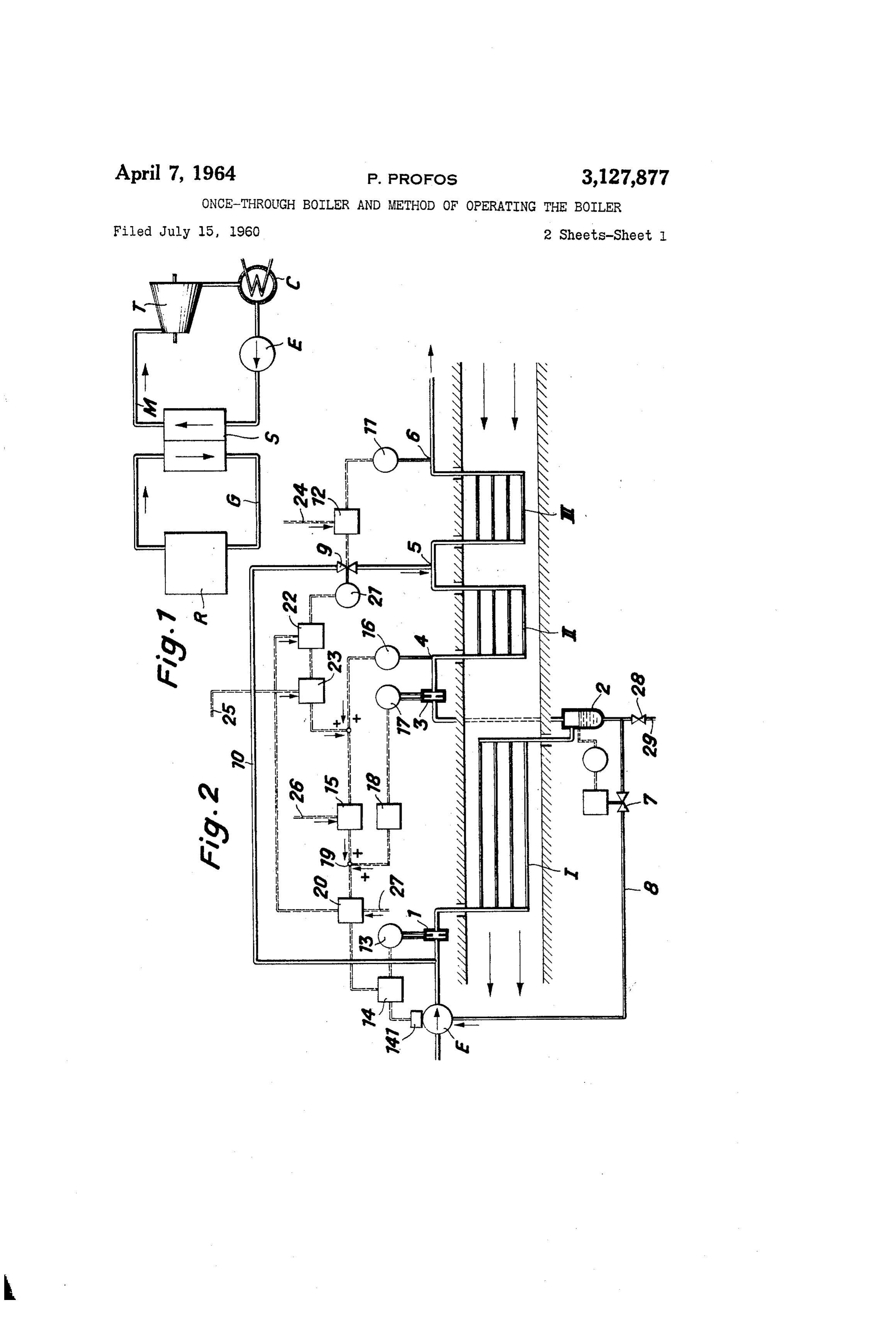
from the first fluid. The superheated vapor is used for FIG. 1 is a diagram showing the coolant circuit and operating a steam turbine or the like for producing me the circuit of the operating medium in a nuclear power chanical power. plant.
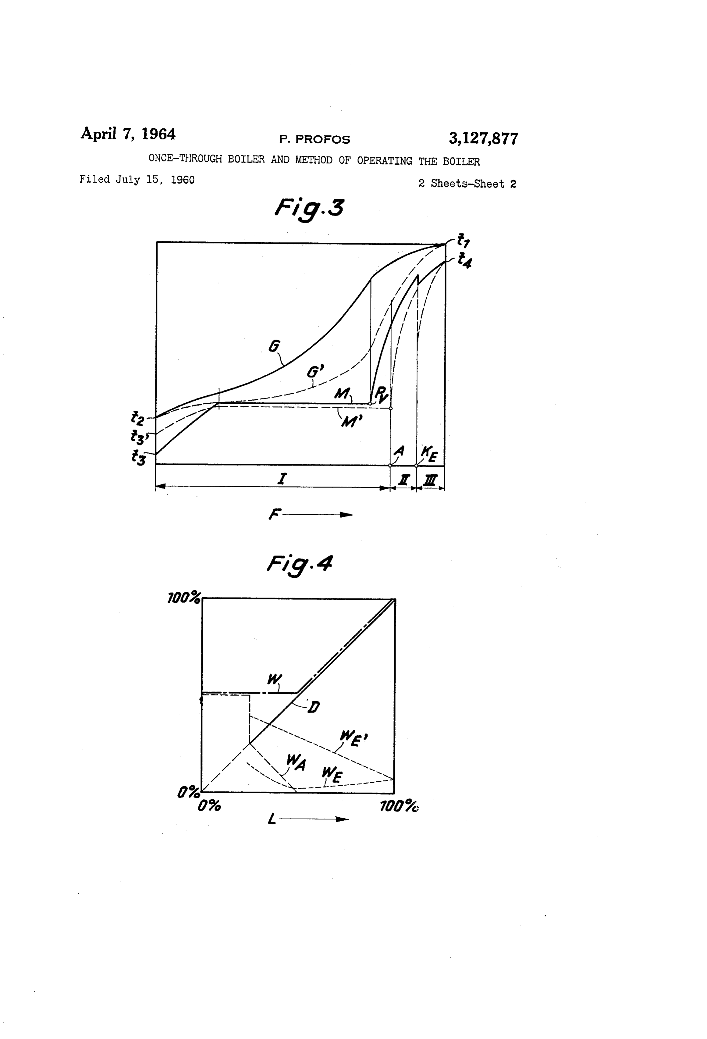
Heat transfer systems as described above are used, for FIG. 2 is a diagrammatic illustration of a heat trans example, in power plants deriving their heat from a 25 fer system forming part of the plant shown in FIG. 1. nuclear reactor. The heating fluid is usually in the gas FIG. 3 is a diagram showing the temperatures of the state and acts as coolant for the reactor. The temper coolant and of the operating fluid as they fow along the atures of this gaseous fluid at the inlet and at the outlet heat transfer surface of the heat transfer system shown of the heat transfer system are maintained constant by in FG, 2.
conventional control apparatus. These temperatures are 30 FIG. 4 is a diagram showing the circulating amounts so low that there is no appreciable heat radiation and of liquid and vapor or steam forming the operating me almost all heat is transferred in the transfer system by dium in a system according to FIG. 2. convection. For changing the amount of heat trans Referring more particularly to FIG. 1, the heat gen ferred in the system to comply with changing load re erated in a nuclear reactor R is transferred in a heat ex quirements of the power plant, the velocity of the reactor 35 changer S from a coolant for the nuclear reactor to an coolant circulating through the reactor and through the operating medium which drives a turbine T. The coolant, heat transfer system is changed. If the load is reduced which is usually a gas, flows in a circuit G in the direction and less vapor or steam is demanded, the velocity of the of the arrows. This first fluid absorbs heat in the nu flow of the second fluid, i.e. the operating medium of the clear reactor R and carries the heat into the heat ex power plant, through the heat transfer system is also re 40 changer S surrendering a portion of the heat to an oper duced. For this reason, depending on the amount of ating medium flowing in the circuit M, whereupon the heat transferred, the point where the operating medium is first fluid is returned to the nuclear reactor R to be completely vaporized moves within the heat transfer heated once more. The operating medium, which is the system. If the two fluids move countercurrent, this point second fluid in the system, is a Substance, for example moves downstream with respect to the direction of flow 45 water, which is vaporized and superheated in the heat of the second fluid when the load is reduced. At low transfer system. The operating medium leaves the heat loads, unstable flow conditions will prevail in the evapo exchanger S and enters the turbine T as Superheated rating portion of the heat transfer system, i.e. in the steam which is expanded in the turbine so that in most portion in which the operating medium is predominantly 50 cases wet steam is exhausted from the turbine and con in the liquid state slugs of liquid will alternate with bub densed in a condenser C. The condensate is returned bies of vapor. These unstable flow conditions cause by means of a pump E to the heat eXchanger S. local superheating, resulting in damage to the tubes of FIG. 2 is a detailed illustration of the heat exchange the system. system S forming part of the system shown in FIG. 1. It is an object of the present invention to provide a Liquid operating medium, for example water, is introduced method and apparatus whereby the flow in the evaporat 55 by means of a feed pump E through an orifice 1 into a ing section of a system for transferring heat from a first heat exchanger portion i where a major portion of the fluid to a second fluid, which flows in counterflow rela liquid is vaporized. The operating medium leaving the tion to the first fluid and whose inlet and outlet tempera heat exchanger portion I is passed through a liquid Sep tures are maintained substantially constant at varying arator 2. The steam or vapor separated therein flows outputs of the heated second fluid, is stabilized at all 60 through an orifice 3 and through a temperature sensing output conditions, i.e. whereby alternate passage of slugs device 4 to a second heat exchanger part II and there of liquid and bubbles of vapor through the evaporating from to a third heat exchanger part III. A controlled section, causing unstable flow conditions in Said Section, amount of liquid operating medium is injected at 5 from is avoided.
In forced flow steam generators, Water Separators are 65 apart pipe a0 into the steam flowing from the part II to the
III. The superheated live steam leaving the heat usually provided at the end of the evaporating Zone. exchanger portion III passes a temperature sensing device These separators are in operation at all loads and Con 6 and is conducted into the turbine T, not shown in FIG. 2. tinuously blow down a portion of the operating medium.
This operation is wasteful. The three heat exchanger parts I, II and I: include in order to avoid this waste and in order to obtain 70 tube packages through which the second fluid, the op the aforestated object of the invention, in the System ac erating medium for the power plant, is conducted. The cording to the invention an amount of liquid operating first fiuid, which is the reactor coolant, flows outside of
Page 4
the tubes and, at least in part, countercurrent to the second and the lines M, M’ show the temperature of the operating fluid. The first fluid consecutively passes over the tubes medium to which heat is transferred from the coolant. of the part III, of the part II, and finally of the part I, The solid lines G and M indicate the temperatures when whereas the second fluid flows first through the tubes of the system is operating at full load. The dotted lines G the part I, then through the tubes of the part II, and and M' indicate the temperatures when the system op finally through the tubes of the part III. Within the in erates at half load. The reactor coolant enters the heat dividual heat exchanger parts, the two heat exchanging transfer system at a substantially constant inlet tempera fluids need not flow countercurrent but may, at least in ture t and is cooled down to a substantially constant out part, flow crosscurrent. let temperature ta. At full load, the operating medium or The liquid discharge side of the liquid separator 2 is O second fluid enters the heat exchanger part I as a liquid at connected by means of a pipe 8 containing a valve 7 the temperature t and is heated to evaporation tempera to the inlet of the feed pump E. A pipe G containing a ture, vaporized and partly superheated in said part I. control valve 9 connects the injecting device 5 to the out The superheating process is continued in the parts II let of the pump E. and III of the heat exchanger. The outlet temperature A conventional device 1 is operatively connected to 15 t of the opearing medium leaving the part III is main and produces signals corresponding to the final steam tained constant by injecting liquid into the operating me temperature sensed by the device 6. These signals are dium while it passes from part II to part III (point KE transferred to a proportional plus reset controller 12 of in FIG. 3). At full load, the entire amount of operating conventional design. The latter actuates the valve 9 con medium introduced into the part I is vaporized upstream trolling the amount of fluid injected into the operating 20 of the point Py which is upstream of the separator 2 medium at 5. (position A in FIG. 3). There is, therefore, no liquid The amount of feedwater supplied to the system is separated in the separator 2. The amount of liquid fed controlled by a control loop including the orifice 1, a into the part I substantially corresponds to the produced conventional device 13 responsive to the rate of flow of amount of vapor or steam and is so great that the flow the operating medium through the orifice 1, a convention 25 in part I is stable.
all proportional plus reset controller 14 and a device 14 When the system operates at partial load, there is a for adjusting the speed of the pump E. For adjusting possibility that the flow in the part I of the heat transfer the set point of the feedwater control loop, a signal pro system is unstable. This is particularly the case at loads duced by a proportional plus reset controller 15 is trans below 50% of full load. Because of the provision of the ferred to the proportional plus reset controller 4. The 30 limiting controller 20, more liquid operating medium is controller 15 is responsive to a signal produced by a de fed into the part I than vapor or steam is withdrawn from vice 16 which is responsive to the temperature of the op part III. The excess operating medium is not evaporated erating medium sensed by the device 4. A conventional in the heat exchanger part I and flows as a liquid through device 17 produces a signal which corresponds to the rate the separator 2 and is conducted therefrom to the iniet of flow of operating medium through the orifice 3. This 35 of the feed pump E. For this reason, the inlet tempera signal passes through a conventional proportional position ture ta, of the operating medium is higher at partial load action controller 18 and is added in a conventional add than at full load. The vapor or steam separated in the ing device 19 to the signal produced by the controller 15. separator 2 is superheated in the parts II and II and The combined signal which is responsive to the tempera 40 leaves the latter at substantially constant temperature ta. ture of the operating medium at 4 as well as to the rate The outlet pressure of the operating medium is main of flow of the operating medium at 3 is conducted through tained constant by conventional means. Due to the a conventional limiting device 20 into the controller 14. smaller pressure drop in the system at partial load, the The limiting device 2it limits reduction of feedwater sup inlet pressure produced by the feed pump is also lower ply so that this supply is not further reduced when the and the evaporation temperature is, consequently, also load drops below half load. The injection control valve lower at partial load as shown by the dotted line M'. 9 actuates a conventional device 21 which produces a The diagram FIG. 4 illustrates the rate of flow of the signal corresponding to the opening of the valve 9 which heat exchange fluids in the system shown in FIG. 2 at signal is transferred through a conventional interrupting various loads or outputs L. The amount of vapor or device 22 to a conventional integrating element 23 which steam taken from the heat transfer system is proportional is connected by a signal conduit to the controller 15. 50 to the load and is indicated by a solid line D which be The purpose of the elements 21 and 23 is to slowly correct gins at about 25% of full load. The amount of liquid the temperature at the point 4 in cooperation with the introduced into the heat transfer system is shown by a controller 5 so that the opening of the injection control dash-dot line W and, when operating between half load valve 9 and the amount of fluid injected at 5 assume a and full load, corresponds to the amount of steam leaving predetermined average. The interrupting element 22 is 55 the system. When the load drops below 50%, the liquid connected to the limiting device 20 and interrupts the fed into the system is not reduced but corresponds to the connection between the elements 2 and 23 whenever the amount defined by the limiting device 26 which amount limiting device 20 comes into action. need not be constant, although, for the sake of simplicity, The conduits 24, 25, 26 and 27 serve for transmitting a horizontal dash-dot line W is shown in FIG. 4 between signals to the controllers 2, 23, 15 and 20, respectively, 60 Zero and half load. The dotted line WA in FIG. 4 indi which signals correspond to the load on the turbine T cates the amount of operating medium separated in the and which serve for adjusting the set points of these con separator 2. When the plant is started and operates be trollers in response to the load. low 25% throughput, all of the second fluid introduced A blowdown pipe 29 is connected to the separator 2, into the part as a liquid is returned to the pump E as a a valve 28 being interposed in the blowdown pipe. The 65 liquid and recirculated. When the load is increased from blown down liquid may be tested to discover the presence 25% to 50%, the liquid separated in the separator 2 is of matter which cannot be vaporized or to discover radio greatly reduced and is Zero at half load when all operat activity, in which case the blowdown liquid would be re ing medium fed into the part I is vaporized therein be moved from the circuit or, after purification, be returned fore reaching the separator 2. to the circuit. O The dotted line W in FIG. 4 represents the amount FIG. 3 is a diagram in which the temperatures are of water injected at 5 into the system. If the separator 2 plotted which prevail in the heat exchange system accord would not be placed at a point of the system where at ing to FIG. 2 along a heat transfer surface F which is full load the entire operating medium is vaporized and formed by the heat exchanger parts I, II and III. The already somewhat superheated, but would be placed, for lines G, G' indicate the temperature of the reactor coolant 75 example, at the full load point Pv in FIG. 3, i.e., where
Page 5
the operating medium reaches the state of dry vapor or tion, upon operation of the heat exchanger below a steam and is not superheated as yet, the amount of water predetermined load;
injected would be according to line W, in FIG. 4. The maintaining a flow rate of the operating medium amount of injected liquid would be much greater in this through the first heat exchange section at which flow case and would require a correspondingly expensive in rate the operating medium leaves said first heat ex jection device. The main disadvantage, however, would change Section in Saturated vapor state and passing be that the evaporating portion I of the heat transfer sys the entire effluent of said first heat exchange sec tem would be still less thermally loaded and the possibility tion into said second heat exchange section, upon of unstable flow in part I would be increased which is operation of the heat exchanger at said predeter contrary to the desired result. O mined load;
The system according to the invention affords mainte maintaining a flow rate of the operating medium nance of the necessary flow stability in heat transfer sys through the first heat exchange section at which flow tems also when they are operated at partial loads so that rate the operating medium leaves said first heat ex damage to the heat transfer surfaces due to local over change section in superheated vapor state and pass heating is avoided. 5 ing the entire effluent of said first heat exchange sec By placing the point at which excess operating medium tion into said second heat exchange section, upon is removed from the system, at the prescribed locality operation of the heat exchanger above said prede the amount of liquid introduced into the superheated op termined load; and erating medium can be held at a minimum so that an injecting liquid operating medium into said second optimal operating efficiency is obtained. 20 heat exhcange section for controlling the tempera claim: ture of the operating medium therein. 1. A method of operating a heat exchanger for cool 3. A heat transfer system including: ing the coolant fluid of a nuclear reactor, the heat ex duct means conducting an initially relatively hot first changer having a tube system forming a once-through fluid, type forced flow vapor generator wherein a vaporizable 25 conduit means placed in said duct means and forming operating medium is forced to flow at variable flow rates a forced flow vapor generator operating under vari corresponding to variable loads in counterflow relation able load conditions, to the coolant issuing from the reactor consecutively said conduit means conducting a relatively cool second through a first heat exchange section, a liquid separator fluid through said duct means in counterflow rela and through a second heat exchange section, the method 30 tion to the first fluid for transferring heat from said comprising: first fluid to said second fluid whereby the point maintaining a flow rate of the operating medium where evaporation of said second fluid is completed through the first heat exchange section at which flow travels upstream in said conduit means upon an in rate the operating medium leaves said first heat ex creasing load and travels downstream in said con change Section in wet vapor state, and 35 duit means upon decreasing load, separating the liquid phase from the vapor phase in means for feeding the second fluid in liquid state into said separator and conducting the vapor phase into said conduit means, said second heat exchange section and diverting the a liquid separator interposed in said conduit means, liquid phase from said second heat exchange sec and tion, upon operation of the heat exchanger below 40 a pipe connected to said separator for receiving liquid a predetermined load; therefrom and connected to said feeding means for maintaining a flow rate of the operating medium returning second fluid in the liquid state to the fluid through the first heat exchange section at which flow fed into said conduit means, rate the operating medium leaves said first heat ex said separator being connected to said conduit means change section in saturated vapor state and passing at a point where said second fluid is in wet vapor the entire effluent of said first heat exchange Section state when the vapor generator is operated below into said second heat exchange section, upon opera a predetermined load, where the second fluid is in tion of the heat exchanger at said predetermined dry, Saturated vapor state when the vapor generator load; and is operated at said predetermined load, and where maintaining a flow rate of the operating medium 50 said second fluid is in the state of superheated vapor through the first heat exchange section at which flow when the vapor generator is operated above said rate the operating medium leaves said first heat ex predetermined load; whereby said separator is dry, change section in Superheated vapor state and pass when the vapor generator is operated at and above ing the entire effluent of said first heat exchange the predetermined load.
section into said second heat exchange section, upon 4. A heat transfer system including: operation of the heat exchanger above said predeter 5 5 duct means conducting an initially relatively hot first mined load. fluid, 2. A method of operating a heat exchanger for cool conduit means placed in said duct means and forming ing the coolant fluid of a nuclear reactor, the heat eX a forced flow vapor generator operating under vari changer having a tube system forming a once-through able load conditions, type forced flow vapor generator wherein a vaporizable 60 said conduit means conducting a relatively cool second operating medium is forced to flow at variable flow rates fluid through said duct means in counterflow rela corresponding to variable loads in counterflow relation tion to the first fluid for transferring heat from said to the coolant issuing from the reactor consecutively first fluid to said second fluid whereby the point through a first heat exchange section, a liquid separator 65 where evaporation of said second fluid is completed and through a second heat exchange section, the method travels upstream in said conduit means upon an in comprising: creasing load and travels downstream in said con duit means upon decreasing load, maintaining a flow rate of the operating medium means for feeding the second fluid in liquid state into through the first heat exchange section at which flow said conduit means, rate the operating medium leaves said first heat ex 70 a liquid separator interposed in said conduit means, change section in wet vapor state, and a pipe connected to said separator for receiving liquid separating the liquid phase from the vapor phase in therefrom and connected to said feeding means for said separator and conducting the vapor phase into returning second fluid in the liquid state to the fluid said second heat exchange section and diverting the fed into said conduit means, liquid phase from said second heat eXchange Sec 75 said separator being connected to said conduit means
Page 6
7 S.
at a point where said second fluid is in wet vapor 5. The method defined in claim 1 wherein said prede state when the vapor generator is operated below a termined load is at least 40% to 60% of the maximum predetermined load, where the second fluid is in dry, load.
saturated vapor state when the vapor generator is op- & 9 erated at said predetermined load, and where said 5 References Cited in the file of this patent second fluid is in the state of superheated vapor UNITED STATES PATENTS when the vapor generator is operated above said pre determined load; whereby said separator is dry, when the vapor generator is operated at and above the
predetermined load, and O FOREIGN PATENTS injection means connected to said conduit means down- 382,731 Great Britain ----------- Nov. 3, 1932 stream of said separator for injecting liquid second 770,091 Great Britain ----------- Mar. 13, 1957 fluid into said conduit means for controlling the tem perature of the second fluid flowing in said conduit means downstream of said separator.
Provenance
- Collection
- Cited prior art
- Original PDF
- patentimages.storage.googleapis.com →
- Filed
- 1960-07-15
- Pages
- 6
- Method
- pdftotext (the PDF's own text layer) + pdftoppm 300dpi page scans
- Source
- Google Patents bibliographic record
- Granted
- 1964-04-07
- Inventors
- Profos Paul; Sulzer AG
- Transcribed from
- patentimages.storage.googleapis.com →