patent · US4441872
Fluid energy conversion system
10 April 1984
Page 1 — bibliographic record
United States Patent (19) (11) 4,441,872 Seale 45 Apr. 10, 1984 w 54 FLUID ENERGY CONVERSION SYSTEM OTHER PUBLICATIONS (76) Inventor: Joseph B. Seale, 31 Avalon Dr., East Wind-Driven Refrigeration Project, Robert Franklin
(21) Appl. No.: 258,751 Wind Energy Development Program, Auroville Jean Pougault et al., 6/82.
(22 Filed: Apr. 29, 1981 Primary Examiner-William E. Wayner Attorney, Agent, or Firm-David A. Rich
Related U.S. Application Data 57 ABSTRACT 63 Continuation-in-part of Ser. No. 254,084, Apr. 14, A fluid-driven pump directly converts fluid kinetic 1981, abandoned.
energy into displacement of a second fluid against a 51) Int. Cl................................... 290 44; FO3D 9/00 pressure differential. In one form of the invention, a 52 U.S. C. ................................... 417/282; 62/228.3; wind turbine is coupled via a rotary shaft crank to a 62/230 reciprocating piston in a large-displacement, double 58) Field of Search ..................... 62/133, 230, 228 C, acting compressor cylinder. In a preferred mode, a 62/228D, 323.4, 236; 122/26; 290/44; 418/282, refrigerant gas is compressed to accomplish heat pump 293, 307, 440 ing and refrigeration. Timed compression-relief valving
controls the time that the wind turbine is coupled to the fluid load to maintain maximum power transfer within
3,653,783 4/1972 Sauder ................................. 417/298 control circuit senses selected parameters to compute 3,664,148 5/1972 Yonezu ...... ....... 62/133 the desired duty cycle and provide an energizing signal 3,844,686 10/1974 Le Blanc ............................. 417/298 to a pair of solenoid relief valves such that the optimum 4,015,962 4/1977 Tompkins ......................... 62/236 X duty cycle is selected for maximum power transfer.
4,336,001 6/1982 Andrew et al.................. 417/282 X 15 Claims, 12 Drawing Figures
Page 2
Drawing sheet — no readable text.
Page 3
Drawing sheet — no readable text.
Page 4
Drawing sheet — no readable text.
Page 5
FIG 4
VOLTAGE .
PROPORTIONAL
SIGNAL
VELOCITY
NVERTER VELOCITY
SIGNAL
ENERGY
DENSITY
ENERGY SIGNAL
CIRCUIT
LOW PRESSURE OW
TRANSDUCER PRESSURE
SIGNAL
UPPER SOLENOID UPPER VALVE 1
VALVE
ONTROL. CIRCUIT
LOWER
WALVE
CONTROL CIRCUIT
Page 6
FIG 5
INVERTNG ACCELERATION SAMPLE/HOLD
DIFFERENTATION SIGNAL AMPLIFFER
NEGATIVE
AVAILABLE
DISPLACEMENT
THREE
INTEGRATION
NEGATIVE, DRIFT MULTIPLER
MINIMUM
HELD TO
ZERO
ENERGY
NEGATIVE
COMPARATOR
PULSE
Éogen
POSITIVE
TIMER
ANSiTIONo.
TO VALVE
Page 7
Drawing sheet — no readable text.
Page 8
FIG 7
INVERTING ACCELERATION SAMPLE/HOLD
POSITIVE SAMPLE ON PULSE NEGATIVE
ENERGY
154 DISPLACEMENT THRESHOLD
NVERTING
NEGATIVE DRIFT,
MINIMUM HELD
TO ZERO
PRESSURE
SIGNAL
DIFFERENCE / D!SPLACEMENT
SIGNA
COMPARATOR
DRIV
COMPARATOR
HIGH OUTPIT
OPENS SOLENOID
RELEF VALVE
Page 9
FIG 8
FLOWCHART, PART
TIME PREVIOUS TO Clock TIME
INITIALIZE VELOCITY TO PRESENT TRANSDUCER READING
INITIALIZE NEGATIVE PEAK ACCELERATION TO ZERO
INITIALIZE "VALVE VOLTAGE" TO "OFF"
SET TIME PRESENT TO CLOCK TIME
INTO A NEW TENTH-SECOND INTERVAL
RELATIVE TO "TIME PREVIOUS
YES
SET "TIME PREVIOUS TO VALUE OF "TIME PRESENT"
READ NEW"VELOCITY VALUE FROM TRANSDUCER 171
SUBTRACT NEW" VELOCITY FROM PREVIOUS "VELOCITY" TO
DETERMINE APPROXMATE ACCELERATION
(ARBTRARY SCALE FACTOR)
JUST CHANGE SiGN FROM
POSITIVE TO NEGATIVE FROM PREVIOUS
STORE PRESENT
YES ACCEERAON
AS"NEGATIVE PEAK
FIG. 9
Page 10
FIG 9
(A) (B) MULTIPLY "NEGATIVE PEAK ACCELERATION
BY NEGATIVE SCALING COEFFICIENT TO
OBTAIN POSITIVE"OPTIMUM ENERGY
ADDVELOCITY
NEW TO'DISPLACEMENT"TOINTEGRATE
(ARBITRARY SCALEFACTOR)
ADD VERY SMALL NEGATIVE NCREMENT TO DISPLACEMENTS
TO CAUSE VERY GRADUAL DOWNWARD ERROR DRIFT OF INTEGRAL
ISYN YES, ESET,
NEGATIVE 1. TO ZERO
NOY
AGE
READ CURRENT TIME
AND SUBTRACT"TRIGGER
TIME" TO OBTAN
TO OFF
VOLTAGE
PREDETERMINED "PULSE
INTERVAL TIME l
Page 11
FIG /O
FLOWCHART, PART 3
READ HIGH AND COMPUTE
Low PREssure TRANDUCER OUTPUTsiph AND P.
"ENERGY DENSITY =
SET DISPLACEMENT ENERGY" s (CONSTANT)x (ENERGY DENSITY)x (DISPLACEMENT)
CONSTANT SELECTED SO UNITS CONSISTENT WITH
CAUSES EXCESS LOAD)
TOP NNEGATIVEWAVE'll
SEAT WALVE CRUICKLY) YES-Y/189
TS) CHAVE ALREADY
is ECORSATESSAYS
TRIGGERED
THIS STROKE)
SETTRIGGER TIME TO CLOCK TIME
TOP
Page 12
DISPLACEMENT
ENERGY
TO MAGNETIC
LOWER SECTION OF CIRCUIT (BELOW LINE)
REPEATED FOR OTHER VALVE, BUT WITH
+VEL AND -VEL INTERCHANGED,OP AMPS:
TL084 FET INPUT AMPS, EXCEPT TWO 741s.
Page 13
Drawing sheet — no readable text.
Page 14
ciently at high tipspeed ratios, i.e., high ratios of tur
FLUID ENERGY CONVERSION SYSTEM bine-tip tangential velocity relative to windspeed up stream of the turbine's disturbing influence. Such high
This application is a continuation in part of my prior speed turbines depend on high tangential velocity of the pending application filed Apr. 14, 1981, entitled Fluid blades to develop large aerodynamic forces resulting in Energy Conversion System, Ser. No. 254,084, now torque. In a given wind, turbine starting torque may be abandoned. only 20% as great as torque at optimum-power speed,
BACKGROUND OF THE INVENTION
or starting torque may be zero. A high tipspeed-ratio turbine may be unable to start a positive-displacement - 1. Field of the Invention 10 pump or compressor under load, even under the load The present invention pertains to fluid energy con torque that would be optimum for energy transfer if the version systems and, more particularly, to energy con turbine were started and operating. For starting, some version systems having variable, load-matching trans device must intervene in the power transmission path, formers for maximizing energy supplied to a load by a such as a clutch, a variable-ratio rotary transmission, or fluid energy source or conversion device, such as a 15 a compression relief valve.
wind turbine or a water turbine, where the fluid energy Once spinning, the turbine should operate at a con source and/or load vary with time. stant tipspeed ratio to maintain a constant advance 2. Discussion of the Prior Art angle of the turbine blade tip and, thus, maintain all Wind and water turbines operate at optimum effi parts of the turbine blades at their most efficient angles ciency only at a specific shaft torque which changes 20 relative to the fluid flow. For constant tipspeed ratio, with variations in the fluid energy source. Optimum rotation speed varies linearly with wind-speed. Since turbine rotation speed, determined by load torque and dynamic pressures (or Bernoulli pressures) vary as the by the fluid energy source, will also vary with time. square of windspeed, torque will vary as the square of Turbine shaft torque will reflect variations in the ener both rotation speed and windspeed at constant tipspeed gy-receiving load, e.g., changing voltage and/or fre 25 ratio. Power, the product of torque and rotation speed, quency, changing water head, or changing gas pres will consequently vary as the cube or rotation speed and sures. To maximize energy or power transfer under windspeed under optimum loading conditions. Accord changing source and load conditions normally requires ingly, there is a great need for variable load-matching a continuously-varying transformer which causes the power or energy transformers for use with wind or torque reflected from the load to the turbine shaft to water powered turbines. As a guideline to the needed equal the instantaneous optimum torque for the fluid range of variability, cube-law, wind energy becomes energy source. negligibly small below roughly eight MPH. For most There is much literature concerning torque-matching sites, windspeeds in excess of eighteen MPH are quite of a turbine to a variable fluid energy source. The ener infrequent, such that the cost of designing a Wind En gy-receiving load is often regulated to be substantially 35 ergy Conversion System (WECS) to operate at top constant with time, e.g. utility lines or near-constant efficiency for some windspeed above eighteen MPH is voltage batteries. Consequently, little attention has been seldom economically justified in terms of average en given to matching variable loads; however, the follow ergy payback. A WECS that operates in a twelve MPH ing examples show that load variation with time is sig average wind regime, that begins power conversion at nificant for several important wind-power applications. eight MPH, that is optimally efficient from eight to First, in a wind-driven water pump used to fill a reser eighteen MPH, and that governs at constant power for voir, hydraulic head, the pump's load, varies with water winds exceeding eighteen MPH, will recover about height in the storage reservoir and with water table 66% as much energy as a similar hypothetical (but im depth, a function of rainfall and pumping-dependent practical) system with optimum efficiency in all wind drawdown. Hydrostatic head variation in a shallow 45 speeds. 30% of the remaining energy represents high well with a highly rainfall-dependent water table, or a end governing loss and only 4% represents the remain storage reservoir with considerable fill depth, is as great ing low-end energy loss. Recovery of the lost 34% is as two-to-one, or greater. usually not economically worthwhile because of design Second, in a compressed air energy system with stor costs. The variation from eight to eighteen MPH is a age tanks, tank pressure will vary over time as stored 50 speed ratio of 2.25, representing a square-law torque energy fluctuates. Back-torque from a fixed-geometry, ratio of roughly 5 and a cube-law power ratio of positive-displacement compressor will vary little with roughly 11. Wind systems designed for higher or lower changing compressor shaft speed but will vary signifi average wind regimes will generally require about the cantly with changing reservoir pressure. same ratio of torque and power variation for full tur Third, in a refrigerant gas compressor driven by a 55 bine/load compensation.
wind or water turbine to pump heat from a varying The matching problem for a water turbine is similar ambient-temperature source into a variable-temperature to the wind turbine case. When hydrostatic head is heat reservoir, refrigerant gas pressures are determined converted to velocity of a water jet hitting a turbine, by temperatures and temperature-dependent vapor velocity varies as the square-root of head pressure. pressures in the evaporator and condenser, and pres Optimum turbine torque varies as the square of both sures will commonly vary by a factor of two or more on rotation velocity and water velocity, therefore linearly both sides of the compressor, causing torque of a fixed with hydrostatic head. Because of blade strength and geometry compressor to vary by a factor of four under cavitation limitations, water turbines do not operate at usual operating conditions. high tipspeed ratios. Consequently, starting torque of The above examples present difficulties in efficiently 65 water turbines is relatively high, unlike many, wind matching variations in the fluid energy source, even if turbine situations. Besides operating with variable head, the load is presumed constant. Considering a wind tur many water turbines use a variable-width nozzle to bine, the most economical wind turbines operate effi regulate flow to the turbine according to energy de
Page 15
mand and water supply variations. Optimum turbine and a wind-driven turbine. For rotating turbine, the torque with a variable nozzle should vary as the prod goal of the controller for the transformer can be de uct of nozzle orifice area times hydrostatic head or, scribed by any one of four equivalent criteria. The equivalently, as the product of orifice area times veloc choice of criterion depends on the particular system ity squared. Optimum turbine speed and tipspeed ratio is embodiment and on what variables are easiest to mea barely affected by nozzle orifice size. Power varies as Sle.
orifice area times velocity cubed, or as orifice area times Criterion 1: Regulate the transformer to achieve the head to the 1.5 power. optimum tipspeed ratio of the turbine under the widest Water turbines are excellent candidates for water possible range of source and load variation. Tipspeed pumping (to provide needed head for irrigation, munici O ratio is defined as the ratio of tangential speed at the pal water supply, etc.), gas compression, and especially turbine tip divided by fluid flow speed ahead of the refrigerant compression for heat pumping, air-condi disturbing influence of the turbine. Constant tipspeed tioning and refrigeration. The water used to drive the ratio implies that turbine angular velocity is propor turbine is an excellent source and sink for thermal en tional to fluid flow velocity. Criterion 1 is valid even ergy. 15 with large variation in density of the fluid energy Most wind electric generators operate without spe SOC.
cific turbine-to-load matching compensation. Average Criterion 2: For substantially, constant energy source load mismatch losses for battery-chargine and resis fluid density, turbine torquer should vary in correct tance heaterloads are less than 5%, provided the system proportion to the square of turbine angular velocity. If is optimized for average load match. With constant this relationship is satisfied, an optimum tipspeed ratio speed alternators and near-constant-speed induction will result.
generators operating into fixed-frequency utility grids, Criterion 3: For substantially constant energy source the best compromise constant turbine speed represents a fluid density, turbine shaft power should vary in correct 5% to 10% loss of recoverable power. A variable-dis proportion to the cube of turbine angular velocity. If placement hydraulic transmission has been used to per 25 energy conversion efficiency is known, measured sys mit a range of constant-tipspeed-ratio turbine operation tem output power may be used to compute turbine shaft while the synchronous alternator operates at constant power. This criterion may be particularly convenient RPM. Most large alternator systems adjust field current for electrical systems, since wattage measurement is with power lever to optimize power factor and mini fairly straightforward.
mize losses as power varies. It appears that little or no Criterion 4: For substantially constant energy source work has been done with time-varying electrical loads fluid density and where shaft rotation is translated into except for using battery storage which absorps the vari a reciprocating stroke, average energy absorped from ations and presents a wind generator with a relatively the turbine on each stroke should vary in proportion to fixed voltage. the square of turbine angular velocity. Peak accelera Adaptive load matching to lift water or compress 35 tion of the reciprocating part is proportional to the gases (including for refrigeration) is much more critical. square of the shaft angular velocity. A high torque, low-tipspeed-ratio multibladed turbine All four criteria compensate for variability in both driving a single-acting piston water pump with buoyant the fluid power source and the load. Except for the first shaft (to avoid even worse starting load) will recover criterion, they are limited to constant fluid density and, less than 30% of potentially available wind energy (not 40 importantly for a turbine in front of a hydropower noz including losses when the turbine furls or turns out of zle, they are limited to constant cross-sectional area of the wind in high winds). Double-acting pumps and the energy-carrying flow. If the size of a jet of water or multicylinder compressors spread the load more evenly other fluid hitting the turbine is allowed to vary, opti through the rotation and can recover, ungoverned, mum tipspeed ratio is not substantially affected, how about 45% to 60% of recoverable power, although the 45 ever, torque and power increase in proportion to flow figure drops drastically if a cheaper high-speed turbine cross-section. Since torque and power are also propor is used. Turbines with automatic clutches can perform tional to fluid density, it can be said that torque and reasonably well, recovering up to 65% of available power should be scaled to the product of density times power before accounting for governing, which lowers flow area. With this in mind, it is possible to generalize the figure. 55 criteria 2 through 4 such that following the phrase Thus, it will be appreciated that there exists a great "square of turbine angular velocity” there is added the need for energy conversion systems capable of maxi phrase "multiplied by the product of density times flow mizing energy transfer from a fluid energy source, such area'.
as a wind or water turbine, to a load, and prior art For certain turbines with very poor low-speed attempts to maximize such energy transfer have not 55 torque, the turbine may remain stalled at low or zero been effective even with the great amount of effort angular velocity even when loaded with a transformed directed thereto. torque that varies as the square of angular velocity in optimum proportions. Such a turbine may need a boost
SUMMARY OF THE INVENTION to start. A Darrieus wind turbine is an example of such Accordingly, it is a primary object of the present a turbine. Turbine starting may be needed before the invention to overcome the above-mentioned disadvan above control criteria become applicable. tages or prior art fluid energy conversion systems with The present invention relates particularly to recipro the use of load-matching transformer means coupled cating piston pumps, including gas compressors. These between the fluid energy source and the load. devices are efficient at dealing with variable-head water The present invention uses a variable transformer that 65 pumping, hydraulic fluid pumping and gas compression matches a time-varying load to the optimum energy for compressed air and heatpump/refrigeration pur transfer requirements of a fluid-energy-driven source, poses. These devices frequently require; substantial including, but not restricted to, a water-driven turbine compensation for time-varying load conditions. For
Page 16
these devices, valve timing is an effective way to source, a load, and a transformer coupled between the achieve variable power transformation. There are three energy source and load for substantially continuously related approaches to variable transformation of energy matching the load to source, within predetermined lim through valve control. The best approach depends on its for the source and the load, such that substantially particulars of the system. maximum energy transfer takes place substantially con In a first approach, the pump cylinder(s) may be tinuously, the transformer including fluid relief means caused to pump on some but not all strokes for reduced for controlling the period during which the source is average torque to the wind turbine shaft. During non coupled to the load.
compression strokes, the pump cylinder(s) remains con The present invention is further generally character nected to the low-pressure manifold either through the 10 ized in a fluid energy conversion system including a inlet valve or through a separate compression relief variable fluid energy source, a variable load, and a servovalve. Turbine angular velocity will jitter some transformer responsive to the energy source and load what with short-term variation in transformed torque, for substantially continuously matching the source and but the flywheel effect of the turbine will smooth angu load, such that substantially maximum energy transfer lar velocity sufficiently to permit efficient operation. 15 takes place substantially continuously, the transformer Coupling to the compresor cylinder (s) may be direct or including fluid relief means for controlling the period via an RPM-changing transmission, usually a step-up during which the source is coupled to the load. transmission. An extra flywheel may be included in the Other objects and advantages of the present invention system, and in the case of a step-up transmission, a will become apparent from the following description of flywheel on the high-speed side is most effective. If 20 the preferred embodiment taken in conjunction with the torque jitter in the transmission or in the wind turbine accompanying drawings.
causes fatigue or wear or noise problems, a torsionally compliant coupling may be placed between a flywheel BRIEF DESCRIPTION OF THE DRAWINGS on the pump shaft and either the transmission or the FIG. 1 is a view of an energy conversion system of turbine. Note that this approach is applicable to both 25 the present invention having a wind turbine driving a compressible and substantially incompressible fluids. heat pump. . . . In a second approach, which applies to substantially FIG. 2 is a view of the compressor and drive mecha incompressible fluids, each compression stroke begins in nism of the energy conversion system of FIG. 1. normal fashion; however, after a certain fraction of a FIG. 3 is a side elevation of the compressor cylinder, cylinder's contents have been pumped, a bypass valve 30 valves and velocity transducer of the compressor of may terminate pumping for the remainder of the stroke FIG. 2.
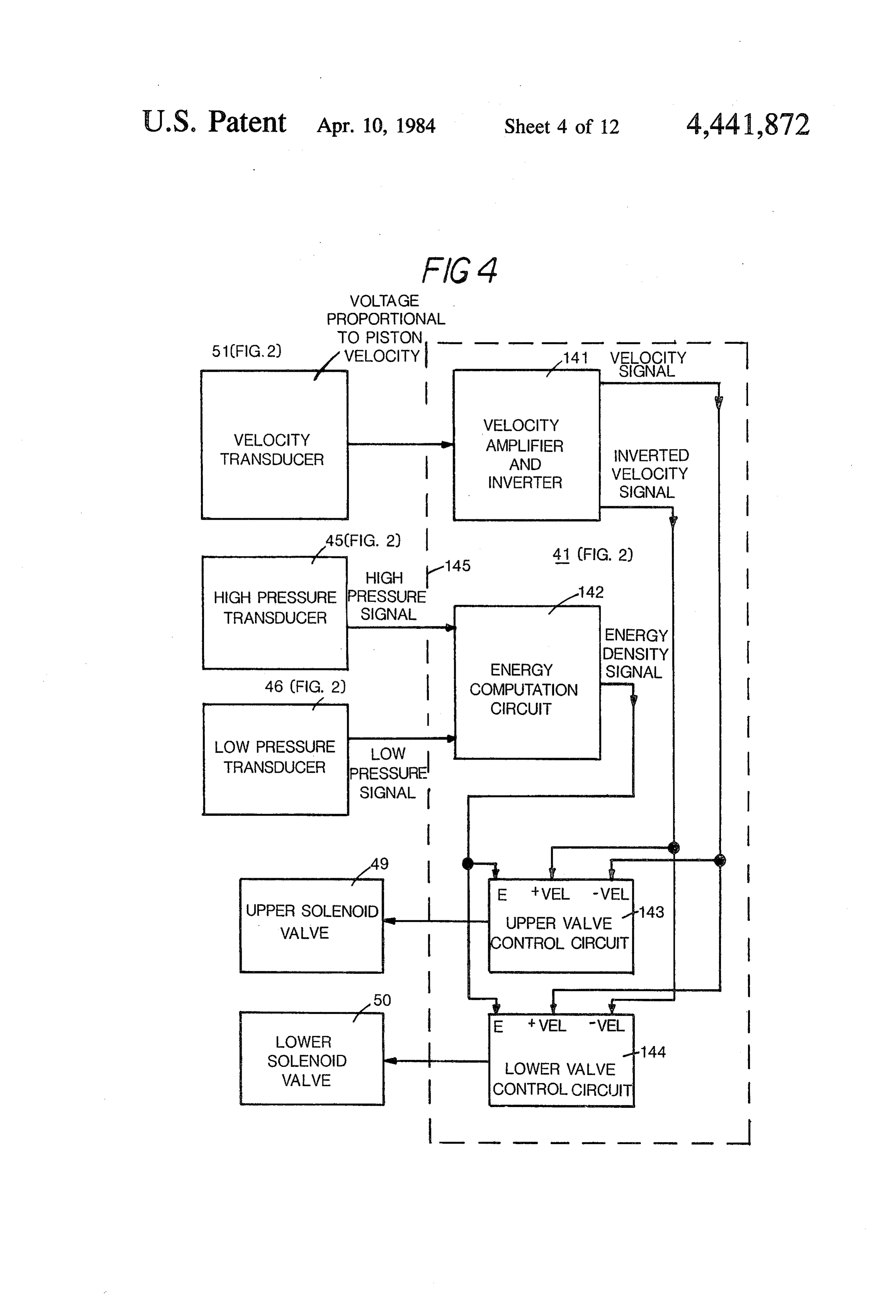
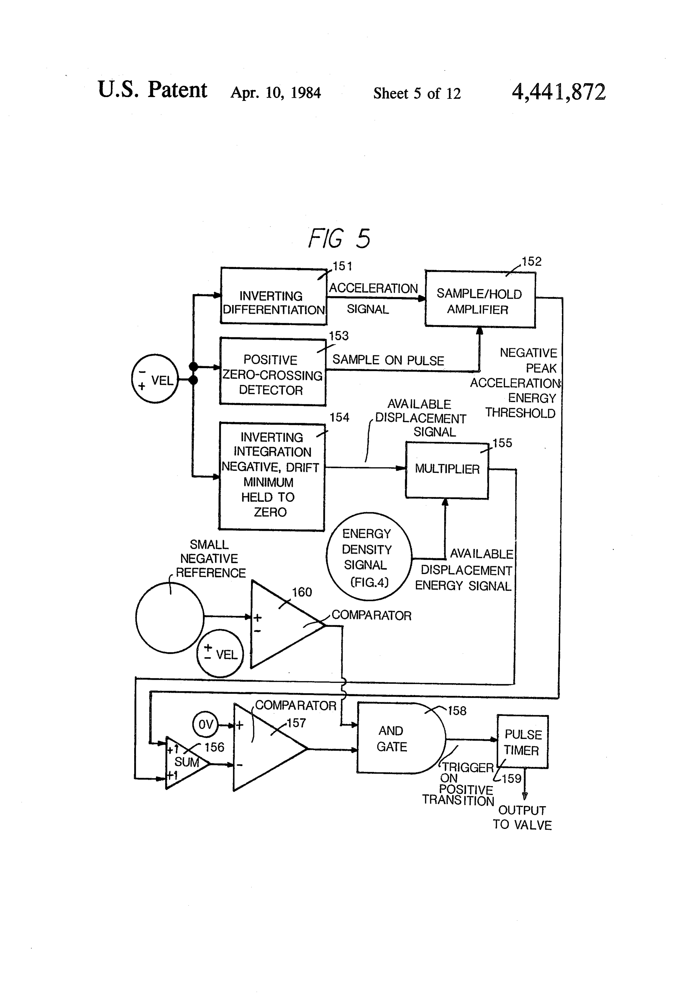
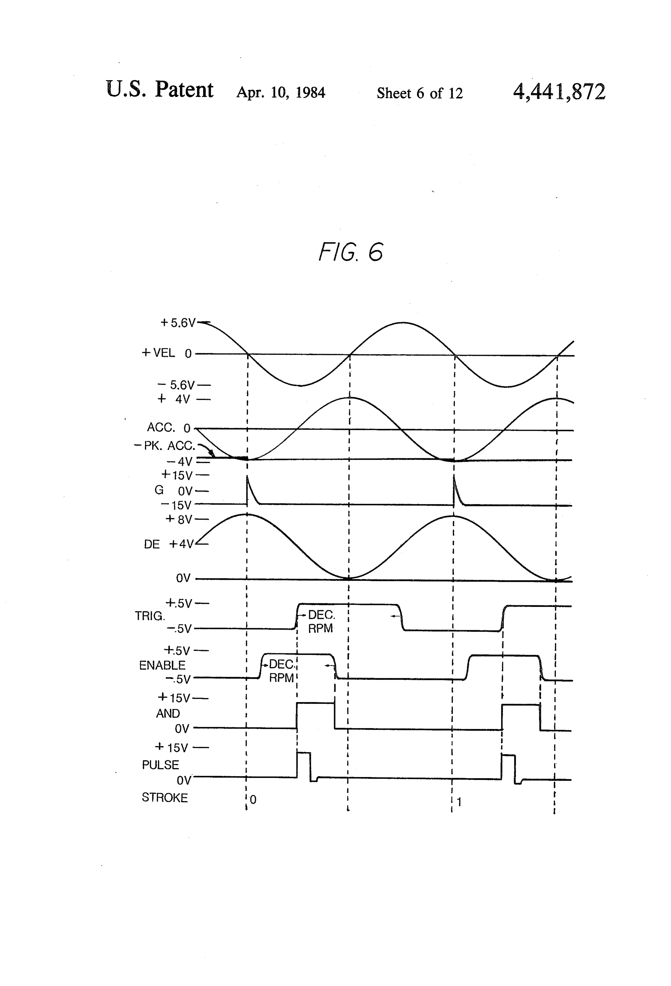
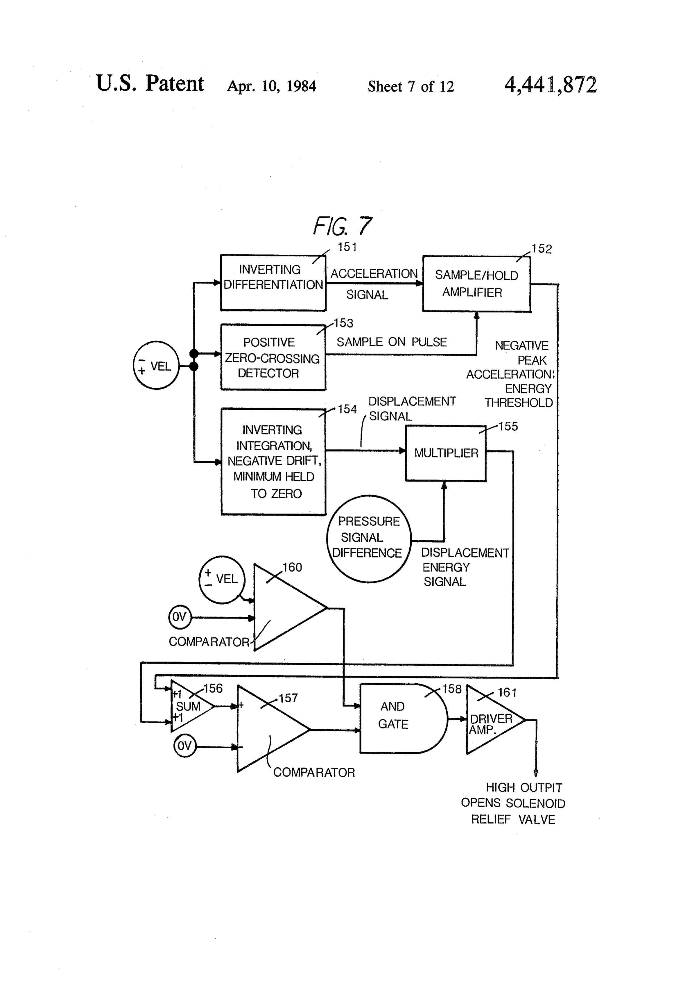
once the fluid has lost its kinetic energy and stopped. FIG. 4 is a block diagram of the electronic contro: Energy transfer per stroke is the integrai of fluid pres circuit for the compressor of FIG. 2. sure times displacement integrated up to the moment FIGS. 5 and 7 are, respectively, schematic block the bypass valve dumps pressure. A control device 35 diagrams of pneumatic and hydraulic valve control adjusts compression relief valve timing to achieve circuits for the energy conversion system of FIG. 1. proper average loading according to one of the afore FIG. 6 illustrates waveforms for the controi circuit of mentioned loading criteria. Operation is smoother using FIG. 5.
this approach, although flywheel energy storage is still FIGS. 8, 9 and 10 are flow charts representing digital reqired to a small degree. 40 operation of an energy conversion system according to A third approach applies to compressible fluids. If the present invention.
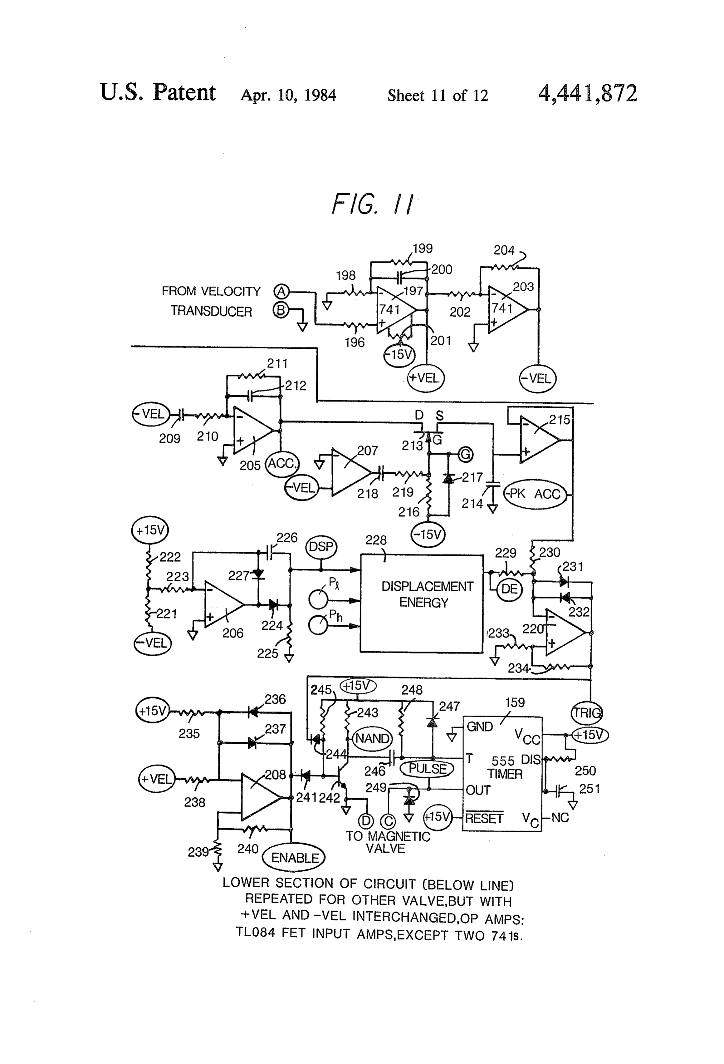
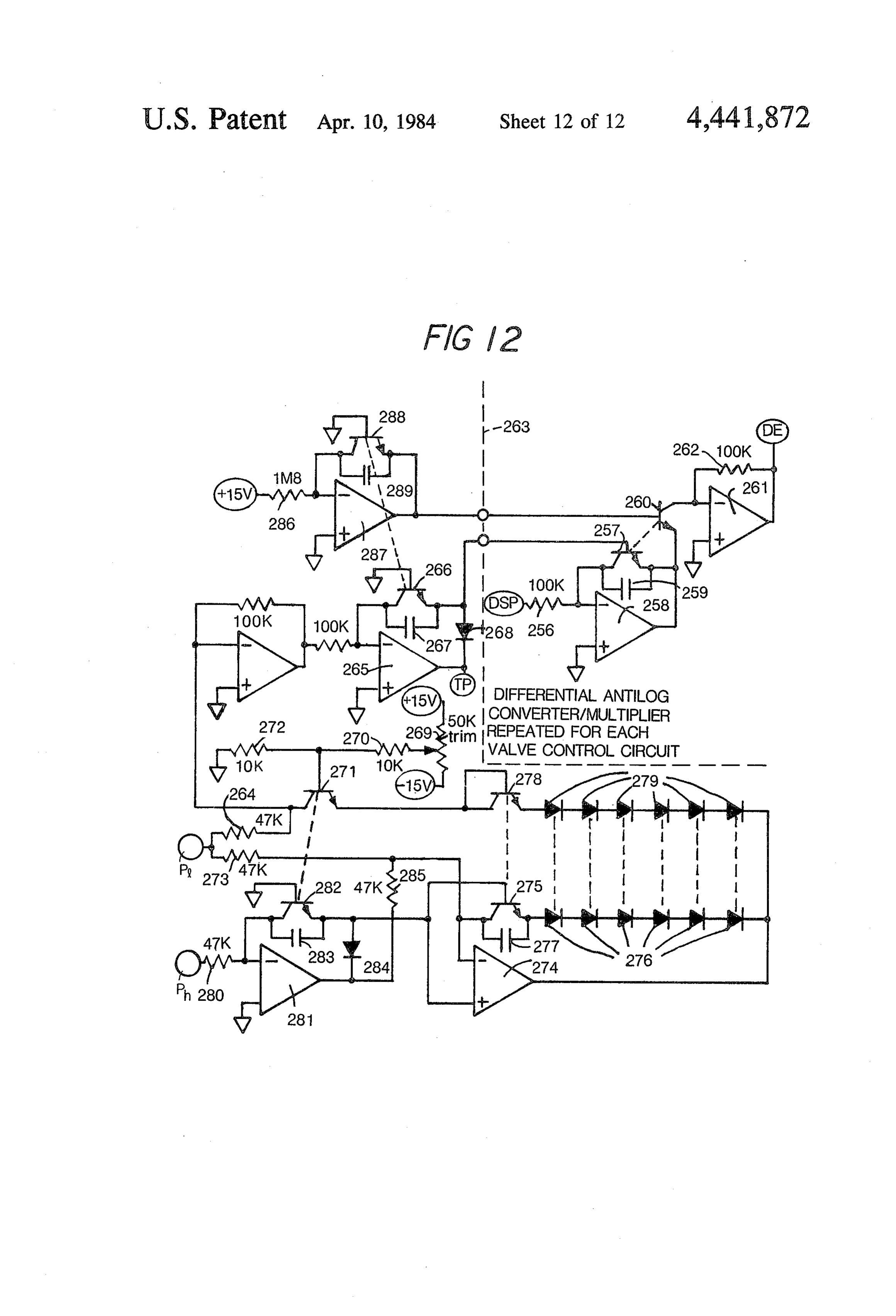
compression relief were applied during the compression FIG. 11 is a more detailed schematic diagram of the stroke, as in the previous approach, energy would be control circuit of FIG. 5.
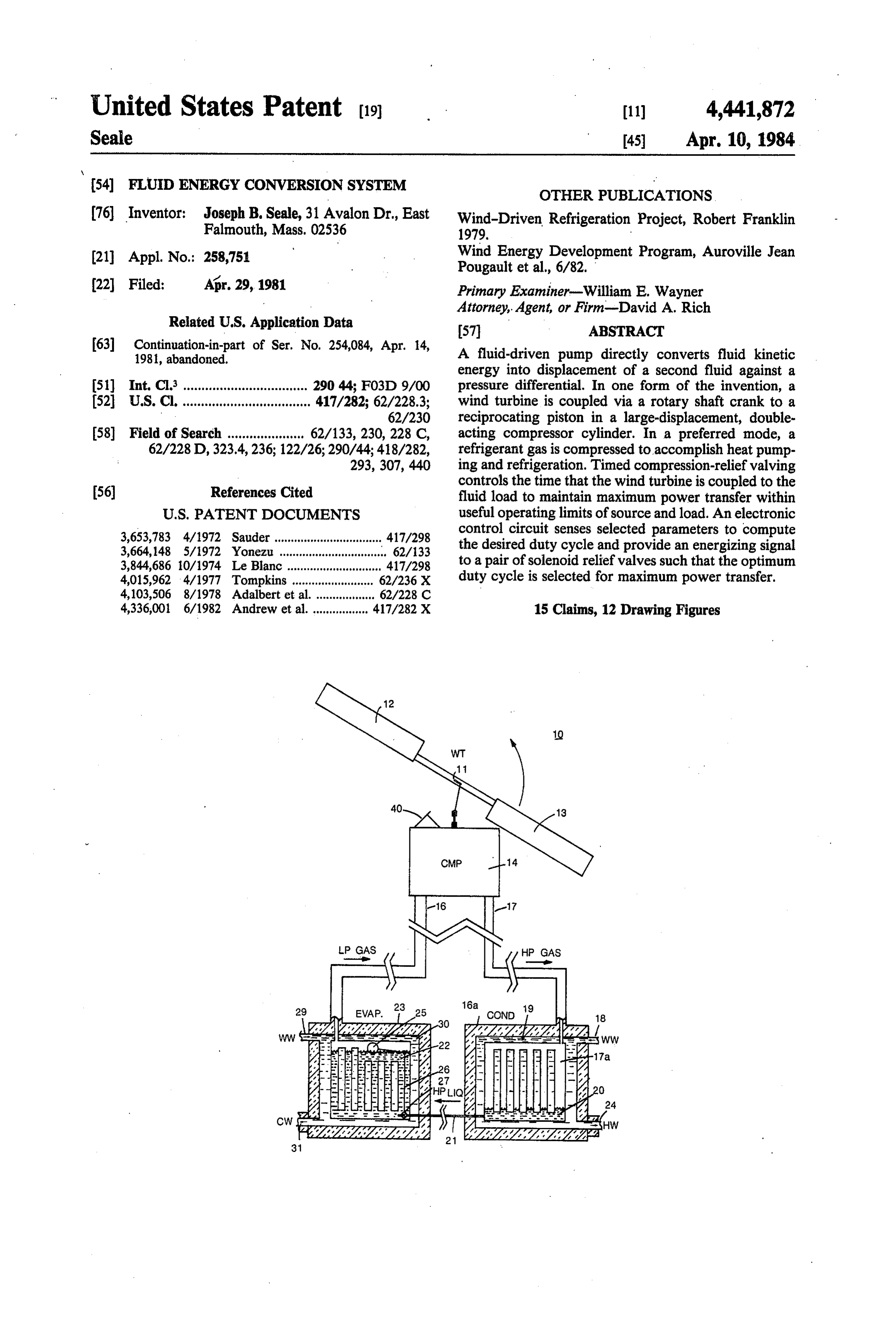
lost to decompression of the compressed cylinder con FIG. 12 is a schematic diagram of the displacement tents. However, it is possible to relieve compression 45 energy computer circuit of FIG. 11. starting at the beginning of the pumping stroke and to DESCRIPTION OF THE PREFERRED then close the compression relief valve (which may also EMBODEMENT be the inlet valve) during the course of the stroke, al lowing compression and pumping of the remaining An energy conversions system 10 according to ths cylinder contents. Some fluid kinetic energy will be 50 present invention is illustrated in FIG. and includes. converted to acoustic energy when the valve interrupts windmill or wind turbine driving a heat pump. The flow. Low-speed piston and generous bypass valve turbine has blades 12 and 13 connected with and rotat. geometries will help minimize this loss. End-of-stroke ing a shaft 11 which is coupled to a compressor 14, dead volume becomes more significant when com shown in more detail in FIG. 2. The compressor prefer, pressed volume per stroke is reduced by late valve 55 ably is located just below the turbine on a tower sup closure. porting the wind turbine. A solar battery is used, as will Another object of the present invention is to control be described in greater detail below, to power the elec the timing of fluid relief valves communicating with a tronic controls as well as the valves. Transmission line cylinder in correlation with piston movement to maxi 17 transmits high pressure gas (or fluid), for example mize energy transfer from a fluid energy source to the propane, to a condenser unit 16a which inciades a con load by controlling the period during which the source densation chamber 17a. Warm water is introduced, via is coupled to the load. a conduit 18, into a chamber 19 which surrounds the . A further object of the present invention is to maxi condensation chamber 17a. Condensed fluid 20 is trans mize energy transfer between a fluid energy source and mitted through a conduit 21 under pressure to an evapr; a load by varying a transformer responsive to the source 65 rator 23. The warm water circulates around the con and/or the load. densing chamber 17a to exit conduit to emerge as The present invention is generally characterized in a heated water. As the condensed fluid is transferred fluid energy conversion system including a fluid energy under pressure from the conduit 21 into an evaporation,

Page 17
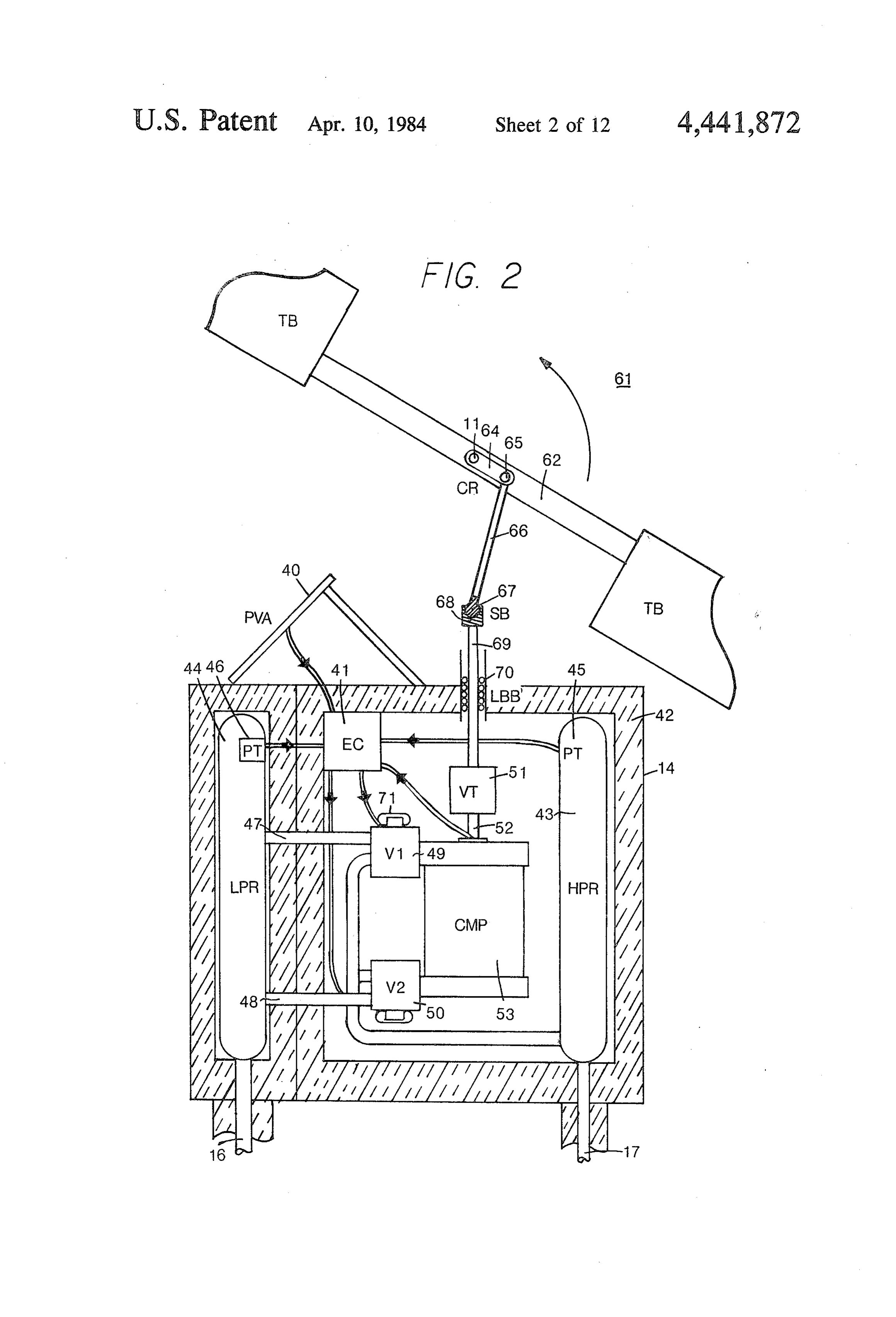
chamber 22, a float 25 senses the level of the fluid and an upper chamber 109 and a lower chamber 110, and a operates to permit fluid to enter until the entire chamber piston 111 is affixed to the piston shaft 69 within the , has been filled. The float is coupled through linkage 26 cylinder wall 108. Fluid, self-sealing, inflatable seals 112 to a valve 27 at the outlet of conduit 21 to control the and 113 are fixed to the piston and move with it to entrance of the condensed fluid under pressure, Warm maintain the seal in the cylinder. The cylinder has a cap water is introduced, via a conduit 29, into a heat-absorb 114 which carries a shaft seal assembly 115 and a pair of ing chamber 30 surrounding the evaporation chamber inflatable annular seals 116 and 117. An O-ring seal 118 and exits as cold water through an exit conduit 31. It is seals the seal assembly to the cap 114. A retainer ring apparent from the above description that hot, water, 119 is fastened, for example by a screw or bolt 120 to the cold water or both can be obtained from heat pum 10 cap 114. A port 121 extends from the upper chamber energy conversion system 10. - 109 to the relief valve assembly 49. A port 122 extends Referring now to FIG. 2, there is illustrated in from greater detail the compressor unit 14 including a trans bly 50.theAlower chamber 110 to the relief-valve assem cap 133 closes chamber 110.
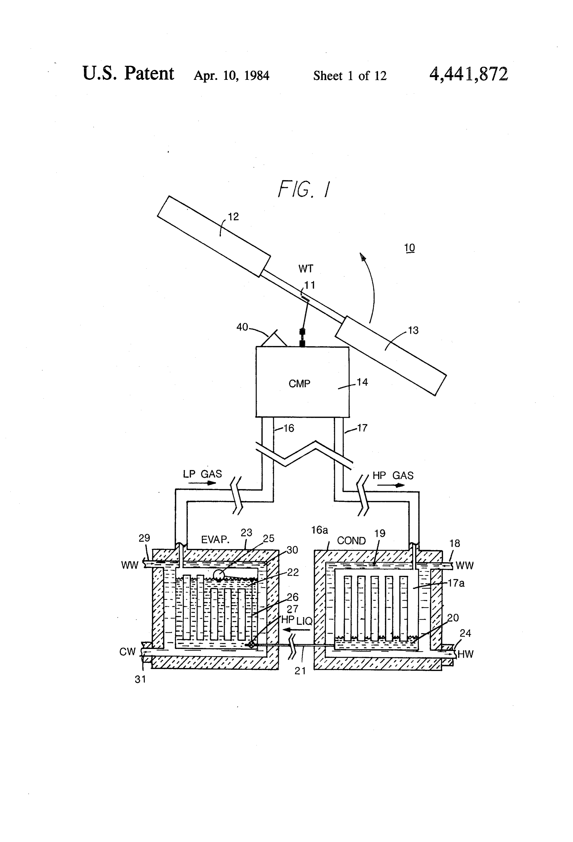
former for matching the energy source to the load. A solar battery includes a photovoltaic array 40 coupled 15 theReferring now to the upper relief-valve assembly 49, to an electronic control circuit with storage batteries 41. the electronic71control solenoid has connections 123 and 124 coupled to circuit and is mounted on a valve
The walls of the compressor unit 14 are lined with housing 125 having a chamber 126therein communicat insulation 42, and the compressor unit includes a high ing with conduit 47 through a low-pressure pressure reservoir 43 and a low-pressure reservoir 44. A chamber 129 therein having a high-pressure outlet outlet and a com pressure transducer 45 in the high-pressure reservoir 20 municating with high-pressure reservoir 43. A valve senses pressure and produces an electrical signal which is coupled to the electronic control circuit 41. A second member
127 carries an armature.controlled by a core solenoid 71. An electric pulse to solenoid. 71 pressure transducer 46 located in the low-pressure res closes member 127 against O-ring 115, isolation cham ervoir 44 is also coupled to the electronic control circuit ber 41. The two reservoirs are insulated from each other, as 25 109 126 from conduit 47. Pressure buildup in chambers and 126 maintains member 127 closed after initial shown, except for conduits 47 and 48 leading to relief valves 49 and 50, respectively. A velocity transducer 51 magnetic closure and until the end of the compression is coupled between shaft 69 and cylinder 53 and is elec stroke. A reed valve 128 is disposed adjacent the valve trically coupled to the electronic control circuit 41. seat and is operated by differential pressure thereacross. Low and high pressure reservoirs 44 and 43 are cou 30 Pressure buildup following magnetic closure of member pled, respectively, to conduits 16 and 17. 127 causes reed 128 to open. The valve assembly 50 is The wind turbine, generally indicated at 61, has a similar in structure with the valve assembly 49 and is blade shaft 62 rotatably fixed to a rotary bearing (not not described in detail again, it being appreciated that a shown) about the turbine shaft 11 which is coupled chamber 132 therein communicates via a low pressure through a linkage plate 64 to a crankpin and second 35 outlet and conduit 48 with low-pressure reservoir 44 rotary bearing 65 (not shown in detail) at the end of a while the upper chamber in the valve housing commu reciprocating drive shaft 66 coupled to a ball joint 67 to nicates via a high pressure outlet to the high-pressure provide a spherical bearing with housing 68. The hous reservoir-43. The solenoid operated valve members 127 ing 68 is affixed to a piston shaft 69 extending through a of valves 49 and 50 are normally open to relieve the linear ball bushing 70 to the velocity transducer 51, the respective chambers in the cylinder; and, therefore, no piston shaft being coupled at 52 to the piston (not compression can take place until such time as the valves shown) in the cylinder 53. are closed.
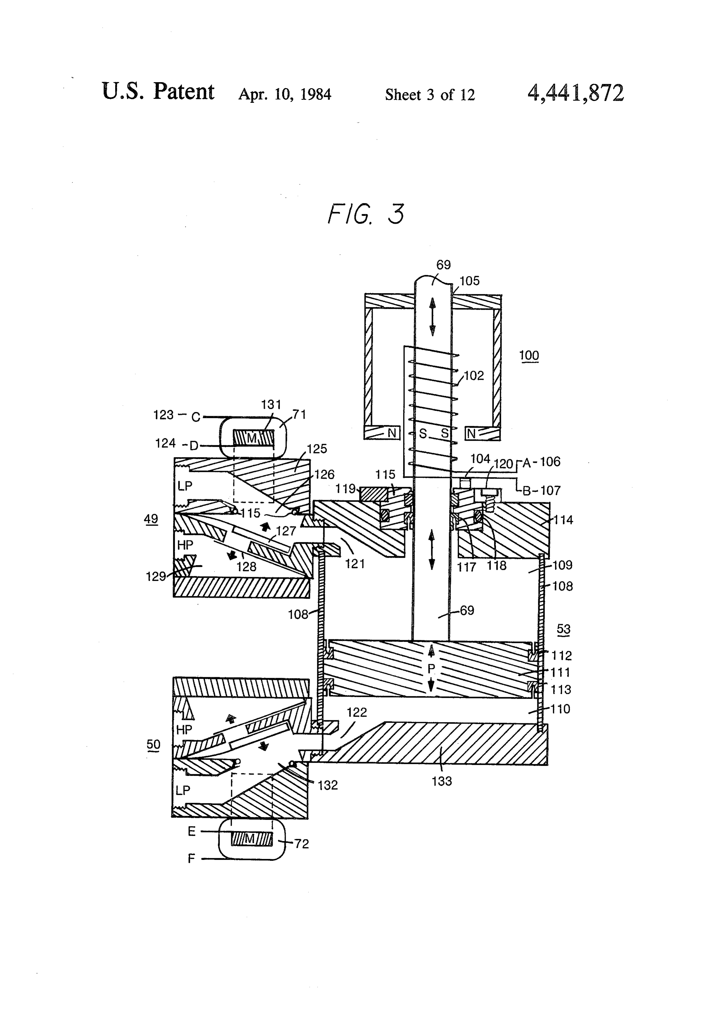
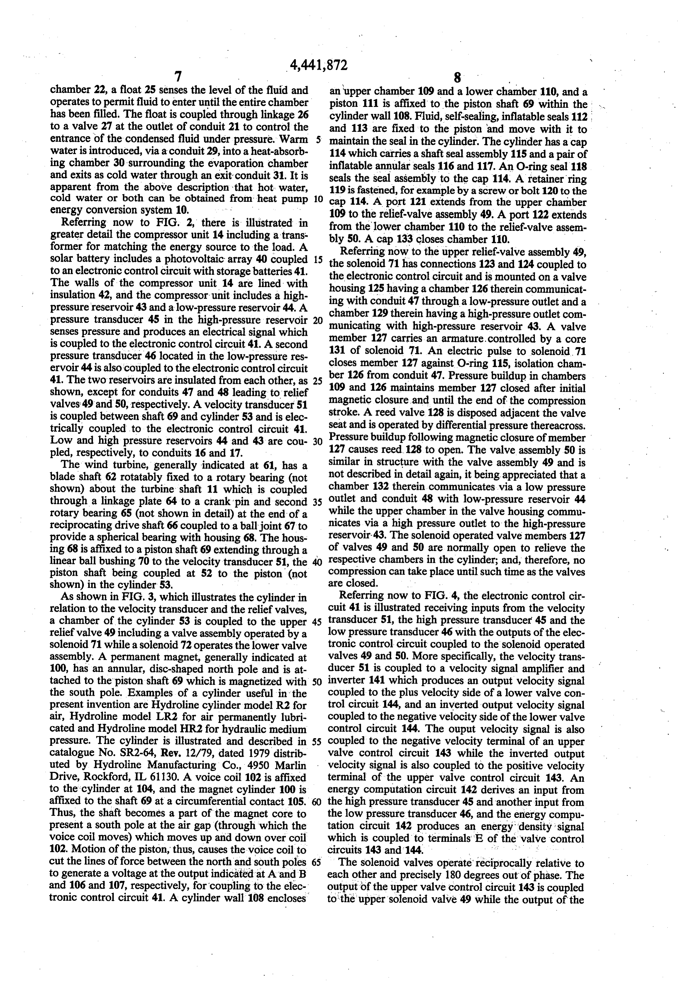
As shown in FIG. 3, which illustrates the cylinder in Referring now to FIG. 4, the electronic control cir relation to the velocity transducer and the relief valves, cuit 41 is illustrated receiving inputs from the velocity a chamber of the cylinder 53 is coupled to the upper 45 transducer 51, the high pressure transducer 45 and the relief valve 49 including a valve assembly operated by a low pressure transducer 46 with the outputs of the elec solenoid 71 while a solenoid 72 operates the lower valve tronic control circuit coupled to the solenoid operated assembly. A permanent magnet, generally indicated at valves 49 and 50. More specifically, the velocity trans 100, has an annular, disc-shaped north pole and is at ducer 51 is coupled to a velocity signal amplifier and tached to the piston shaft 69 which is magnetized with 50 inverter 141 which produces an output velocity signal the south pole. Examples of a cylinder useful in the coupled to the plus velocity side of a lower valve con present invention are Hydroline cylinder model R2 for trol circuit 144, and an inverted output velocity signal air, Hydroline model LR2 for air permanently lubri coupled to the negative velocity side of the lower valve cated and Hydroline model HR2 for hydraulic medium control circuit 144. The ouput velocity signal is also pressure. The cylinder is illustrated and described in 55 coupled to the negative velocity terminal of an upper catalogue No. SR2-64, Rev. 12/79, dated 1979 distrib valve control circuit 143 while the inverted output uted by Hydroline Manufacturing Co., 4950 Marlin velocity signal is also coupled to the positive velocity Drive, Rockford, IL 61130. A voice coil 102 is affixed terminal of the upper valve control circuit 143. An to the cylinder at 104, and the magnet cylinder 100 is energy computation circuit 142 derives an input from affixed to the shaft 69 at a circumferential contact 105. the high pressure transducer 45 and another input from Thus, the shaft becomes a part of the magnet core to the low pressure transducer 46, and the energy compu present a south pole at the air gap (through which the tation circuit 142 produces an energy density signal voice coil moves) which moves up and down over coil which is coupled to terminals E of the valve control 102. Motion of the piston, thus, causes the voice coil to circuits 143 and 144. . .. . . cut the lines of force between the north and south poles 65 The solenoid valves operate reciprocally relative to to generate a voltage at the output indicated at A and B each other and precisely 180 degrees out of phase. The and 106 and 107, respectively, for coupling to the elec output of the upper valve control circuit 143 is coupled tronic control circuit 41. A cylinder wall 108 encloses to the upper solenoid valve 49 while the output of the
Page 18
lower valve control circuit 144 is coupled to the lower. comparator 157 is supplied to one input of AND gate solenoid valve 50. 158. Comparator 160 derives an input at its positive A pneumatic valve control circuit is illustrated in terminal of a small negative reference voltage while the FIG. 5, and this circuit, with only a change in connec input to the negative terminal is the positive or non tion, can be used for either the upper valve control inverted velocity signal. The output of the comparator circuit 143 or the lower valve control circuit 144. FIG. is coupled to the AND gate 158, and the output of the 7 illustrates a hydraulic valve control circuit with the AND gate triggers on positive transition a pulse timer essential differences between the pneumatic and hy 159 which produces an energizing pulse output to the draulic valve control circuits being that, under hydrau solenoid valve.
lic conditions, energy transfer starts immediately with 10 When the circuit shown in FIG. 5 is used as an upper the stroke and is maintained until it gets a signal to stop valve control circuit, the phase or polarity of the input after the desired amount of energy has in fact been velocity signals are reversed such that the input to the transferred. This implies that the solenoid relief valve is differentiator 151, the zero-crossing detector 153, and normally closed and must be held open in order to the integrator 154 is positive or non-inverted and the terminate the energy transfer cycle. 15 input to the comparator 160 is negative or inverted. The valve control circuit of FIG. 5 receives the two The operating conditions for the valve control circuit amplified and inverted output velocity signals 180 de will be discussed with respect to five conditions: grees out of phase from velocity amplifier and inverter a. below the minimum threshold 41 depending upon whether the circuit is also used for b. in the minimum range the upper or lower valve. An inverting differentiation 20 c. in the medium range circuit 151 produces an acceleration signal which is d. at the maximum range sampled based on an enabling pulse provided by a posi e.greater than the maximum range. tive zero-crossing detector 153. A sample/hold ampli Below the minimum threshold the velocity input to fier 152 produces an output signal that is a measure of the comparator 160 is insufficient to produce a plus peak negative acceleration and provides a measure of 25 signal to the AND gate; and therefore, no output can be the energy transfer required by the system. An invert produced irrespective of the relationship between the ing integrator 154 produces an available displacement peak acceleration and the available displacement energy signal which is supplied to a multiplier 155 along with signal.
the energy density signal supplied by energy computa In the minimum range, the acceleration signal is in the tion cicuit 142. The output of the multiplier 155 is an 30 same range as the available displacement energy signal available displacement energy signal which is coupled so that the summing amplifier 156 produces a zero. The to a summing amplifier. The other input to the summing output of the comparator 157 then supplies a one to the amplifier is the negative peak acceleration from sam AND gate; and since the output of the comparator 160 ple/hold amplifier 152. The output is supplied to a com reflects the actual velocity of the piston shaft as being parator 157 and compared with a zero reference volt 35 large enough to confirm that there is available energy, age. The comparator output is applied to an input of the AND gate triggers on a positive transition to trigger AND gate 158. If the output of the comparator is posi the pulse timer 159 to produce a pulse output to the tive, it creates an enable condition for the output of the solenoid valve. This is true throughout the operating AND gate. Another comparator 160 compares the ve range, the difference between minimum, medium and locity output signal from velocity amplifier and inverter 40 maximum ranges pertaining to when the energy transfer 141 with a reference voltage; and, if the velocity is takes place and, in particular, relating to when the sole sufficient, the output of the comparator 160 is positive noid valve is energized for the purpose of establishing and the AND gate 158 produces a trigger on a positive communication with the high pressure reservoir 43. transition to produce a pulse that is supplied through a Within the normal operating range from minimum to pulse timer 159 to the solenoid valve to hold the mem 45 maximum, the signal supplied to AND gate 157 from ber closed as shown in FIG. 3. the comparator 160 is on or enabling shortly after the More particularly, referencing the lower valve con compression stroke starts. At the upper range or the trol circuit, the negative or inverted velocity signal is maximum normal operating condition, the signal starts supplied to inverting differentiation circuit 151 and to almost immediately after the beginning of the stroke positive zero-crossing detector 153, and to inverting 50 and varies depending upon the velocity of the piston integrator circuit 154. The integrator 154 has a negative which is a function of the angular velocity of the wind drift with a minimum held to zero. The output of the turbine shaft. During normal operating range when the zero-crossing detector is an enabling pulse which is available displacement energy signal from the multiplier coupled to the sample/hold amplifier 152. The output of 155 is greater then the negative peak acceleration en the integrator 154 is an available displacement signal, 55 ergy threshold from the amplifier 152, the comparator i.e. the measure of the remaining volume in the cylinder 157 output is a disabling signal and, therefore, waits 53. The available displacement signal is coupled to a until the available displacement energy has dropped to multiplier 155 deriving another input from the energy a point where it is less than or equal to the negative peak density signal produced by the energy computation acceleration. Above the normal maximum operating circuit 142. The multiplier 155 produces an output avail condition, the valve is closed most of the time to com able displacement energy signal coupled to summing municate directly from the lower cylinder chamber to amplifier 156 which receives as its other input the peak the high pressure reservoir. It will, of course, be operat acceleration signal derived from the sample/hold ampli ing at that point at less than optimum for energy trans fier 152. The output of the amplifier 156 is supplied to a fer.
comparator 157. The plus terminal of the comparator 65 Referring now to FIG. 6, there is illustrated a series 157 is grounded to provide a zero volt reference while of waveforms relating to the operation of the electronic the output of the amplifier 156 is supplied to the nega control system for the lower valve control circuit. tive terminal of the comparator 157. The output of the When the velocity goes negative correlates with the
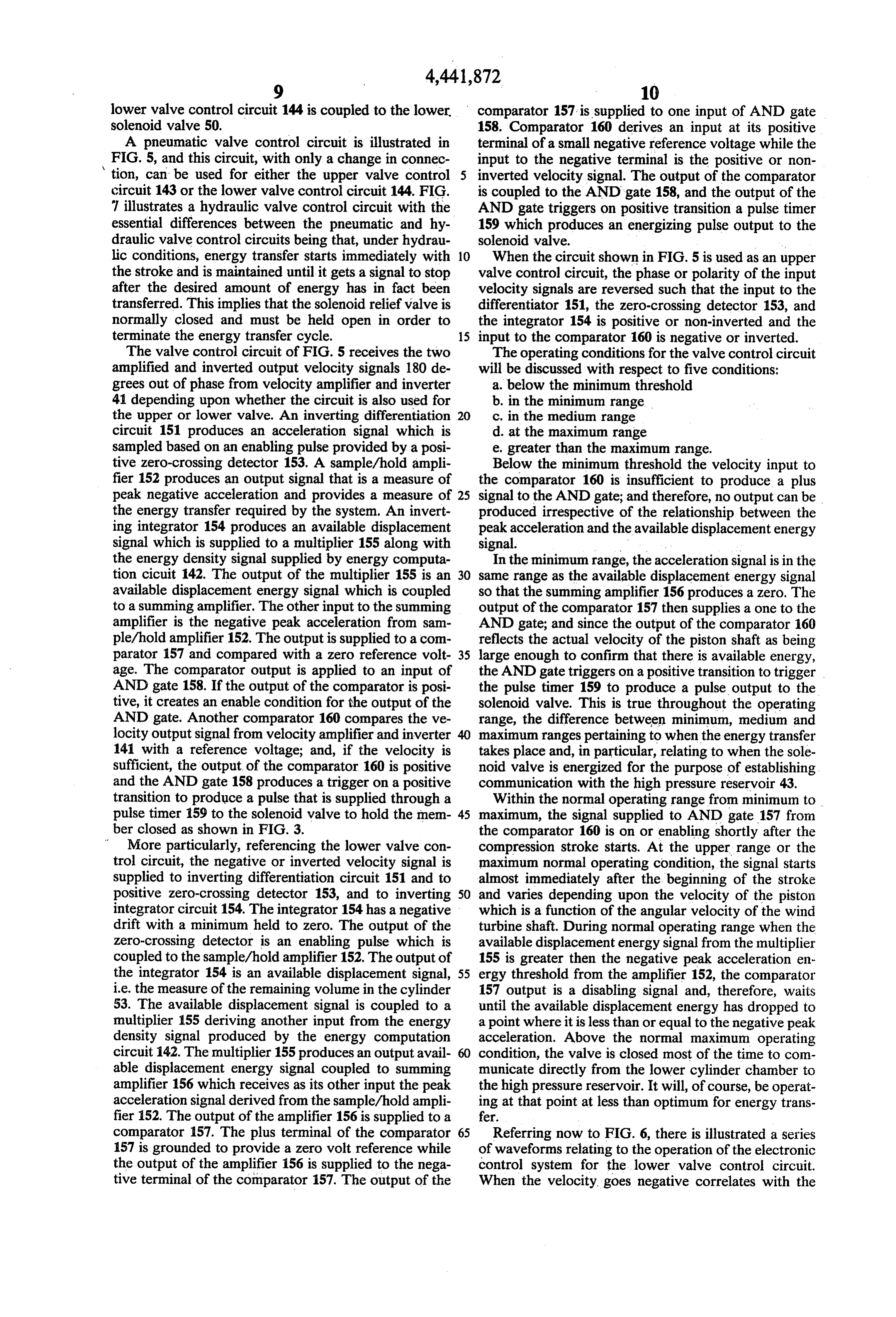
Page 19
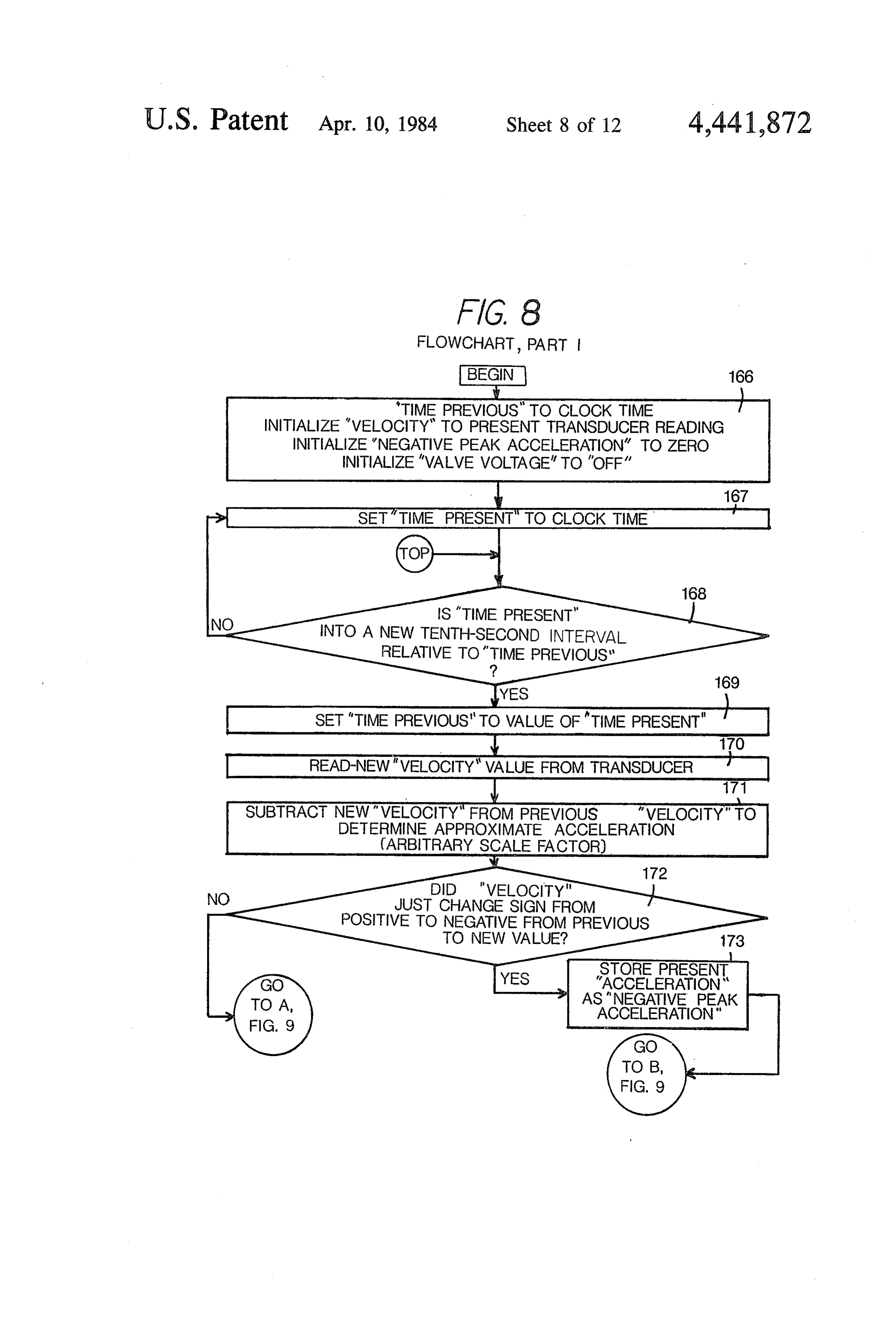
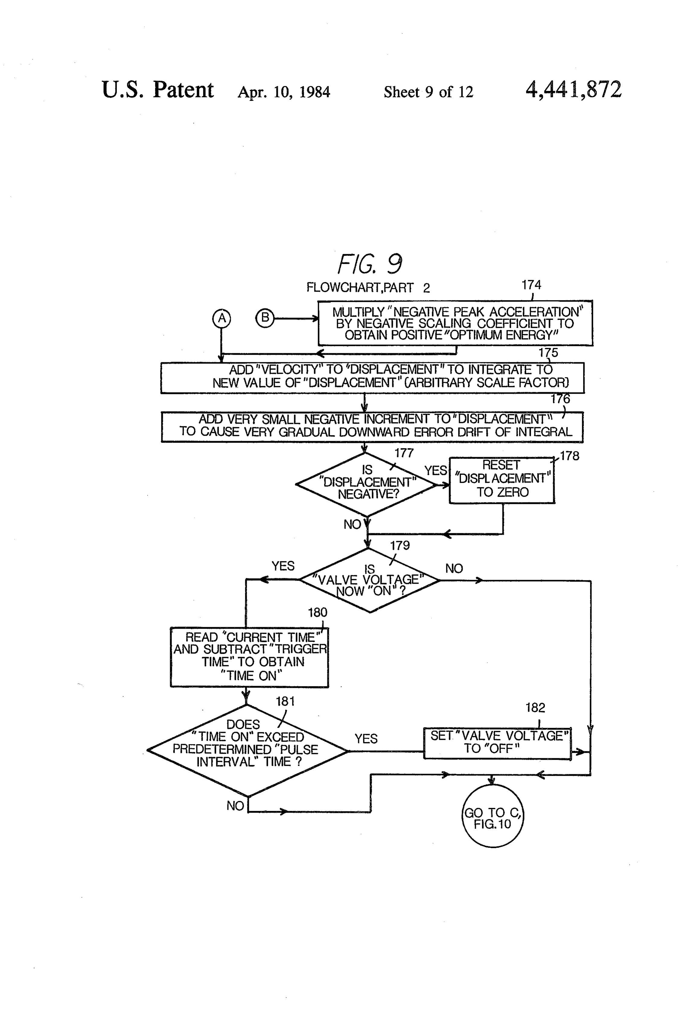
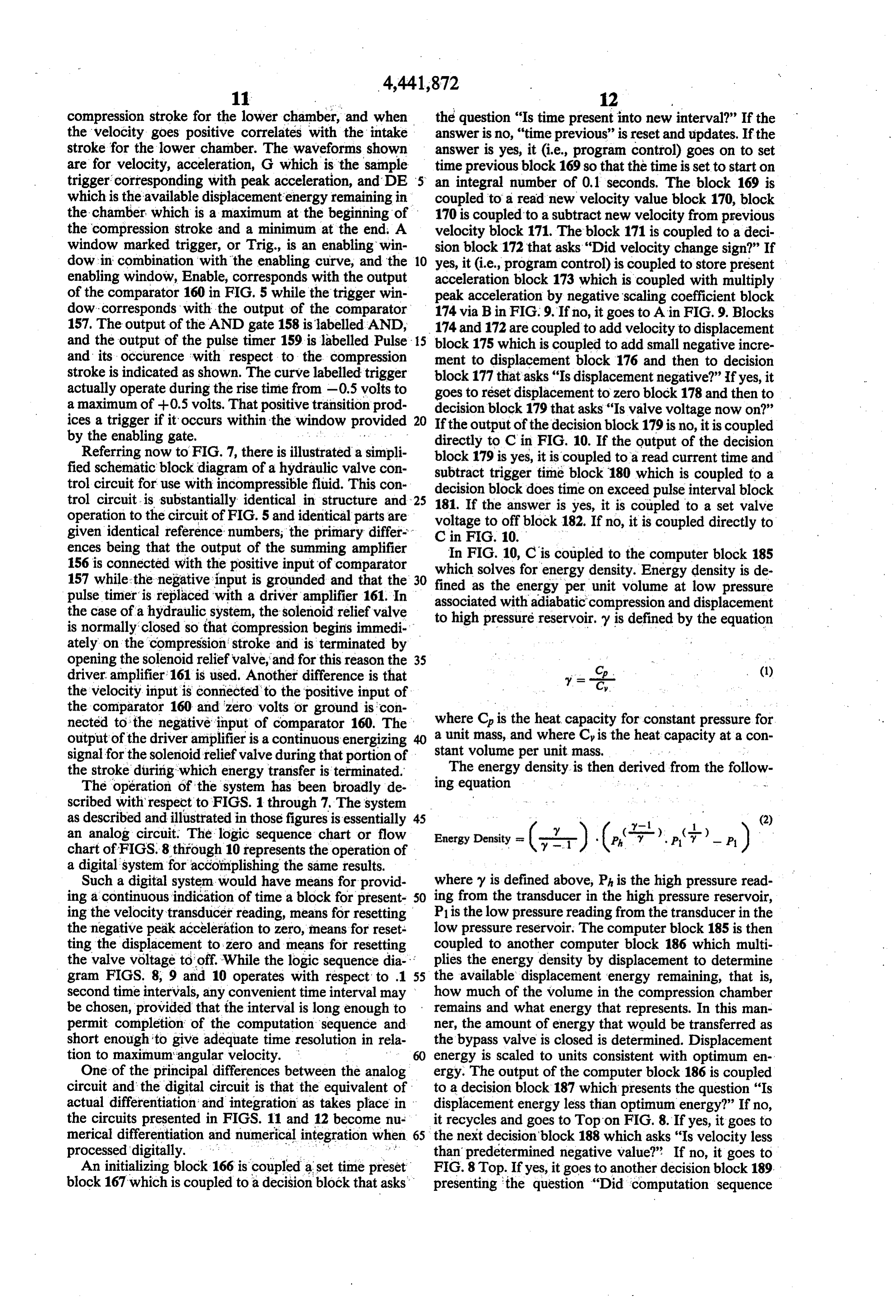
compression stroke for the lower chamber, and when the question "Is time present into new interval?" If the the velocity goes positive correlates with the intake answer is no, "time previous" is reset and updates. If the stroke for the lower chamber. The waveforms shown answer is yes, it (i.e., program control) goes on to set are for velocity, acceleration, G which is the sample time previous block 169 so that the time is set to start on trigger corresponding with peak acceleration, and DE 5 an integral number of 0.1 seconds. The block 169 is which is the available displacementenergy remaining in coupled to a read new velocity value block 170, block the chamber which is a maximum at the beginning of 170 is coupled to a subtract new velocity from previous the compression stroke and a minimum at the end. A velocity block 171. The block 171 is coupled to a deci window marked trigger, or Trig, is an enabling win sion block 172 that asks "Did velocity change sign?" If dow in combination with the enabling curve, and the 10 yes, it (i.e., program control) is coupled to store present enabling window, Enable, corresponds with the output acceleration block 173 which is coupled with multiply of the comparator 160 in FIG. 5 while the trigger win peak acceleration by negative scaling coefficient block dow corresponds with the output of the comparator 174 via B in FIG. 9. If no, it goes to Ain FIG. 9. Blocks 157. The output of the AND gate 158 is labelled AND, 174 and 172 are coupled to add velocity to displacement and the output of the pulse timer 159 is labelled Pulse - 15 block 175 which is coupled to add small negative incre and its occurence with respect to the compression ment to displacement block 176 and then to decision stroke is indicated as shown. The curve labelled trigger block 177that asks "Is displacement negative?”If yes, it actually operate during the rise time from -0.5 volts to goes to reset displacement to zero block 178 and then to a maximum of -0.5 volts. That positive transition prod decision block 179 that asks "Is valve voltage now on?" ices a trigger if it occurs within the window provided 20 If the output of the decision block 179 is no, it is coupled by the enabling gate. directly to C in FIG. 10. If the output of the decision Referring now to FIG. 7, there is illustrated a simpli block 179 is yes, it is coupled to a read current time and fied schematic block diagram of a hydraulic valve con subtract trigger time block 180 which is coupled to a trol circuit for use with incompressible fluid. This con decision block does time on exceed pulse interval block trol circuit is substantially identical in structure and 25 181. If the answer operation to the circuit of FIG. 5 and identical parts are voltage to off blockis182. yes, it is coupled to a set valve If no, it is coupled directly to given identical reference numbers; the primary differ C in FIG, 10.
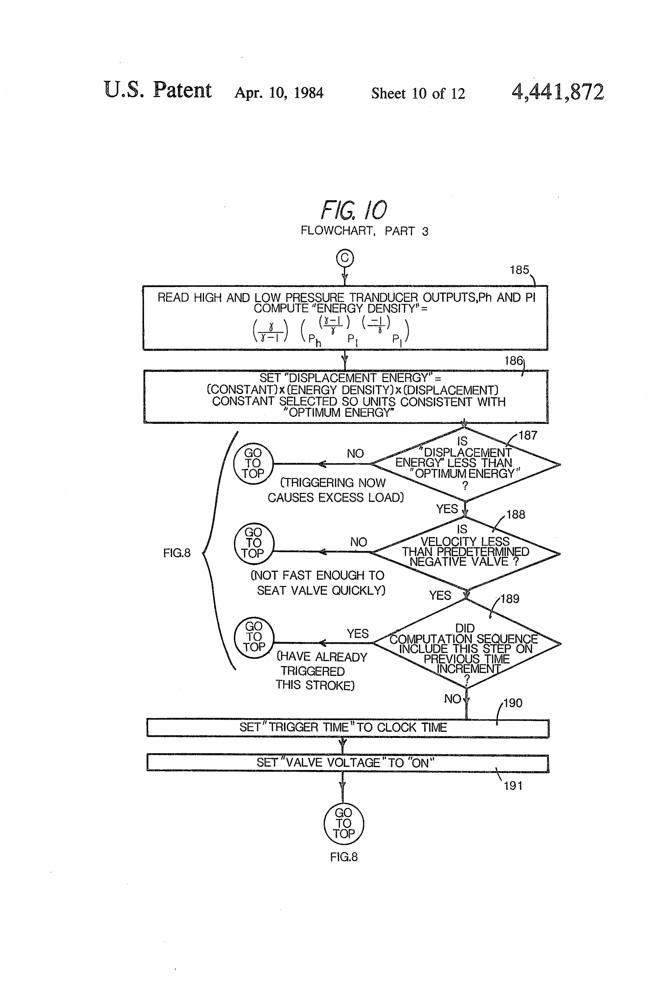
ences being that the output of the summing amplifier In FIG. 10, C is coupled to the computer block 185 156 is connected with the positive input of comparator 157 while the negative input is grounded and that the 30 fined assolves which the for energy density. Energy density is de energy per unit volume at low pressure pulse timer is replaced with a driver amplifier 161. In associated with adiabatic the case of a hydraulic system, the solenoid relief valve to high pressure reservoir.compression
and displacement defined by the equation is normally closed so that compression begins immedi ately on the compression stroke and is terminated by opening the solenoid relief valve, and for this reason the 35 driver amplifier 161 is used. Another difference is that 2. - (1) the velocity input is connected to the positive input of the comparator 160 and zero volts or ground is con nected to the negative input of comparator 160. The where C is the heat capacity for constant pressure for a unit mass, and where Cy is the heat capacity at a con output of the driver amplifier is a continuous energizing 40 stant volume per unit mass. . ," signal for the solenoid relief valve during that portion of The energy density is then derived from the follow the stroke during which energy transfer is terminated. ing equation
The operation of the system has been broadly de scribed with respect to FIGS. 1 through 7, The system as described and illustrated in those figures is essentially 45 y-1 1. (2) an analog circuit. The logic sequence chart or flow chart of FIGS. 8through 10 represents the operation of Energy Daily -(yzi ) (e. y . (3-) a digital system for accomplishing the same results.
Such a digital system would have means for provid where y is defined above, Phis the high pressure read ing a continuous indication of time a block for present- 50 ing from the transducer in the high pressure reservoir, ing the velocity transducer reading, means for resetting P1 is the low pressure reading from the transducer in the the negative peak acceleration to zero, means for reset low pressure reservoir. The computer block 185 is then ting the displacement to zero and means for resetting coupled to another computer block 186 which multi the valve voltage to off. While the logic sequence dia plies the energy density by displacement to determine gram FIGS. 8, 9 and 10 operates with respect to .1 55 the available displacement energy remaining, that is, second time intervals, any convenient time interval may how much of the volume in the compression chamber be chosen, provided that the interval is long enough to remains and what energy that represents. In this man permit completion of the computation sequence and ner, the amount of energy that would be transferred as short enough to give adequate time resolution in rela the bypass valve is closed is determined. Displacement tion to maximum angular velocity. 60 energy is scaled to units consistent with optimum en One of the principal differences between the analog ergy. The output of the computer block 186 is coupled circuit and the digital circuit is that the equivalent of to a decision block 187 which presents the question "Is actual differentiation and integration as takes place in displacement energy less than optimum energy?” If no, the circuits presented in FIGS. 11 and 12 become nu it recycles and goes to Top on FIG. 8. If yes, it goes to merical differentiation and numerical integration when 65 the next decision block 188 which asks "Is velocity less processed digitally. .. . . than predetermined negative value?” If no, it goes to An initializing block 166 is coupled a set time preset FIG. 8 Top. If yes, it goes to another decision block 189. block 167 which is coupled to a decision block that asks presenting the question "Did computation sequence
Page 20
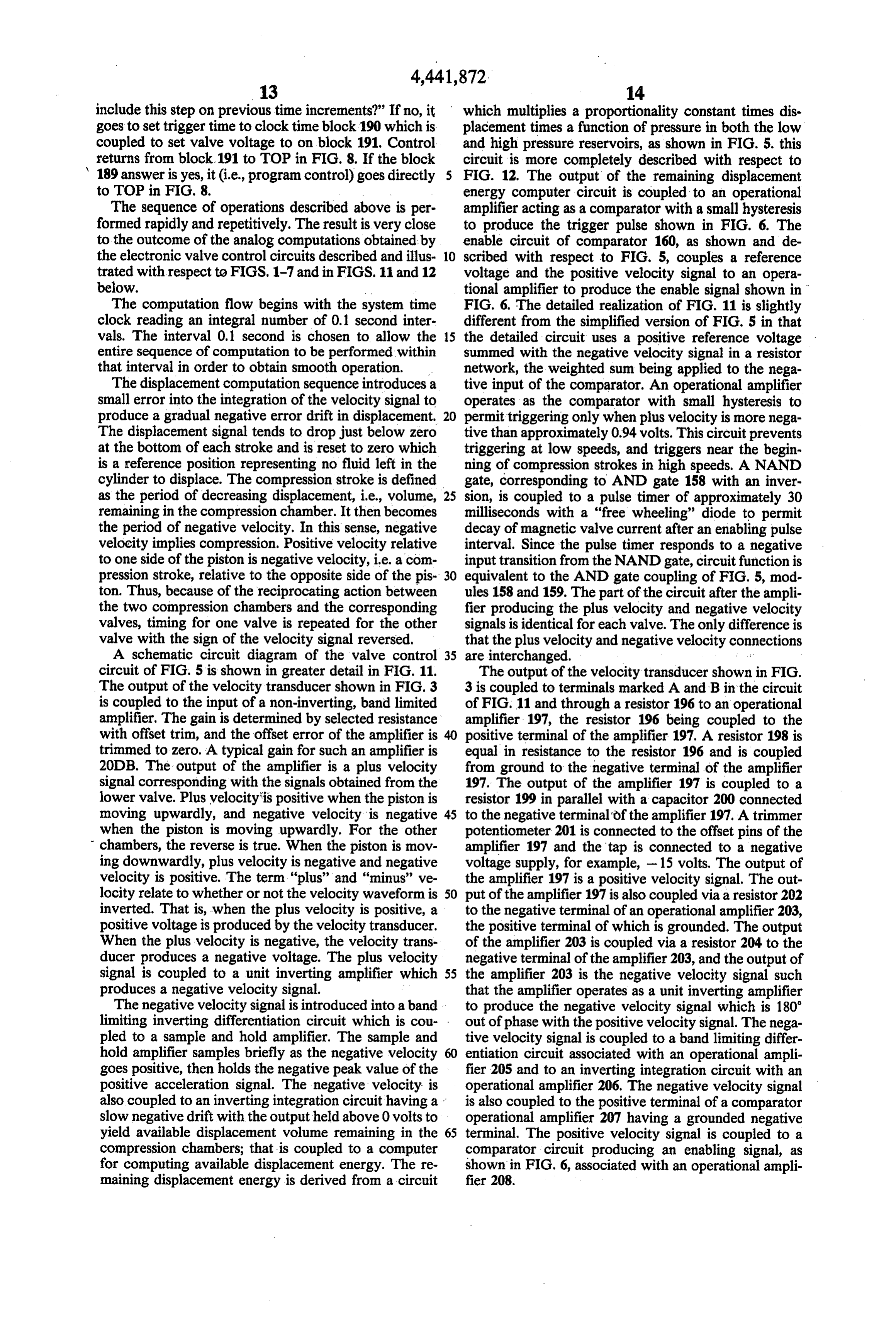
include this step on previous time increments?' If no, it which multiplies a proportionality constant times dis goes to set trigger time to clock time block 190 which is placement times a function of pressure in both the low coupled to set valve voltage to on block 191. Control and high pressure reservoirs, as shown in FIG. 5. this returns from block.191 to TOP in FIG. 8. If the block circuit is more completely described with respect to 189 answer is yes, it (i.e., program control) goes directly FIG. 12. The output of the remaining displacement to TOP in FIG. 8. - energy computer circuit is coupled to an operational The sequence of operations described above is per amplifier acting as a comparator with a small hysteresis formed rapidly and repetitively. The result is very close to produce the trigger pulse shown in FIG. 6. The to the outcome of the analog computations obtained by enable circuit of comparator 160, as shown and de the electronic valve control circuits described and illus 10 scribed with respect to FIG. 5, couples a reference trated with respect to FIGS. 1-7 and in FIGS. 11 and 12 voltage and the positive velocity signal to an opera below. tional amplifier to produce the enable signal shown in The computation flow begins with the system time FIG. 6. The detailed realization of FIG. 11 is slightly clock reading an integral number of 0.1 second inter different from the simplified version of FIG. 5 in that vals. The interval 0.1 second is chosen to allow the 15 the detailed circuit uses a positive reference voltage entire sequence of computation to be performed within summed with the negative velocity signal in a resistor that interval in order to obtain smooth operation. network, the weighted sum being applied to the nega The displacement computation sequence introduces a tive input of the comparator. An operational amplifier small error into the integration of the velocity signal to operates as the comparator with small hysteresis to produce a gradual negative error drift in displacement. 20 permit triggering only when plus velocity is more nega The displacement signal tends to drop just below zero tive than approximately 0.94 volts. This circuit prevents at the bottom of each stroke and is reset to zero which triggering at low speeds, and triggers near the begin is a reference position representing no fluid left in the ning of compression strokes in high speeds. A NAND cylinder to displace. The compression stroke is defined gate, corresponding to AND gate 158 with an inver as the period of decreasing displacement, i.e., volume, 25 sion, is coupled to a pulse timer of approximately 30 remaining in the compression chamber. It then becomes milliseconds with a "free wheeling' diode to permit the period of negative velocity. In this sense, negative decay of magnetic valve current after an enabling pulse velocity implies compression. Positive velocity relative interval. Since the pulse timer responds to a negative to one side of the piston is negative velocity, i.e. a com input transition from the NAND gate, circuit function is pression stroke, relative to the opposite side of the pis 30 equivalent to the AND gate coupling of FIG. 5, mod ton. Thus, because of the reciprocating action between ules 158 and 159. The part of the circuit after the ampli the two compression chambers and the corresponding fier producing the plus velocity and negative velocity valves, timing for one valve is repeated for the other signals is identical for each valve. The only difference is valve with the sign of the velocity signal reversed, that the plus velocity and negative velocity connections A schematic circuit diagram of the valve control 35 are interchanged. .. circuit of FIG. 5 is shown in greater detail in FIG. 11. The output of the velocity transducer shown in FIG. The output of the velocity transducer shown in FIG. 3 3 is coupled to terminals marked A and B in the circuit is coupled to the input of a non-inverting, band limited of FIG. 11 and through a resistor 196 to an operational amplifier. The gain is determined by selected resistance amplifier 197, the resistor 196 being coupled to the with offset trim, and the offset error of the amplifier is 40 positive terminal of the amplifier 197. A resistor 198 is trimmed to zero. A typical gain for such an amplifier is equal in resistance to the resistor 196 and is coupled 20DB. The output of the amplifier is a plus velocity from ground to the negative terminal of the amplifier signal corresponding with the signals obtained from the 197. The output of the amplifier 197 is coupled to a lower valve. Plus velocity is positive when the piston is resistor 199 in parallel with a capacitor 200 connected moving upwardly, and negative velocity is negative 45 to the negative terminal of the amplifier 197. A trimmer when the piston is moving upwardly. For the other potentiometer 201 is connected to the offset pins of the chambers, the reverse is true. When the piston is mov amplifier 197 and the tap is connected to a negative ing downwardly, plus velocity is negative and negative voltage supply, for example, -15 volts. The output of velocity is positive. The term "plus' and "minus' ve the amplifier 197 is a positive velocity signal. The out locity relate to whether or not the velocity waveform is 50 put of the amplifier 197 is also coupled via a resistor 202 inverted. That is, when the plus velocity is positive, a to the negative terminal of an operational amplifier 203, positive voltage is produced by the velocity transducer. the positive terminal of which is grounded. The output When the plus velocity is negative, the velocity trans of the amplifier 203 is coupled via a resistor 204 to the ducer produces a negative voltage. The plus velocity negative terminal of the amplifier 203, and the output of signal is coupled to a unit inverting amplifier which 55 the amplifier 203 is the negative velocity signal such produces a negative velocity signal. that the amplifier operates as a unit inverting amplifier The negative velocity signal is introduced into aband to produce the negative velocity signal which is 180 limiting inverting differentiation circuit which is cou- . out of phase with the positive velocity signal. The nega pled to a sample and hold amplifier. The sample and tive velocity signal is coupled to a band limiting differ hold amplifier samples briefly as the negative velocity entiation circuit associated with an operational ampli goes positive, then holds the negative peak value of the fier 205 and to an inverting integration circuit with an positive acceleration signal. The negative velocity is operational amplifier 206. The negative velocity signal also coupled to an inverting integration circuit having a is also coupled to the positive terminal of a comparator slow negative drift with the output held above 0 volts to operational amplifier 207 having a grounded negative yield available displacement volume remaining in the 65 terminal. The positive velocity signal is coupled to a compression chambers; that is coupled to a computer comparator circuit producing an enabling signal, as for computing available displacement energy. The re shown in FIG. 6, associated with an operational ampli maining displacement energy is derived from a circuit fier 208.
Page 21
The negative velocity signal is coupled, more particu pair of diodes 236 and 237 are coupled in inverse paral larly, through a capacitor 209 in series with a resistor lel between the output of the amplifier 208 and its nega 210 to the negative terminal of amplifier 205, the posi tive input terminal. The plus velocity signal is coupled tive terminal being grounded. The output of the ampli through a resistor. 238 to the negative terminal of the fier 205 is coupled through a resistor 211 connected in amplifier 208. The positive input terminal of the ampli parallel with a capacitor 212 to the negative terminal of fier is coupled through a resistor 239 to ground and the amplifier, the output of the amplifier 205 being the through a resistor 240 to the output of the amplifier. As acceleration signal and being coupled to the drain of a field effect transistor 213. The source of the field effect mentionedsignal above, the output of the amplifier is the transistor is coupled to ground through a capacitor 214 10 enabling shown in FIG. 6 and is coupled through a diode 241 to the base of an NPN transistor 242. The and to the positive terminal of an operational amplifier output of the amplifier is connected to the cathode of 215 in the sample and hold amplifier circuit.
The gate of the field effect transistor 213 is coupled thethe diode 241, and the anode of diode 241 is connected through a resistor 216 to a source of negative voltage, to base of transistor 242. The emitter of the transis for example - 15 volts, with resistor 216 in parallel with 15 a resistor 243 toand tor is grounded, the collector is connected through a positive supply, for example -- 15 a diode 217. The anode of the diode is connected to the negative supply, and the cathode is connected to the volts. The trigger signal from the output of amplifier gate of the transistor 213. The waveform at the gate of anode coupled
connected to the cathode of a diode 244 having an directly to the base of the transistor the field effect transistor 213 is shown as G in FIG. 6.
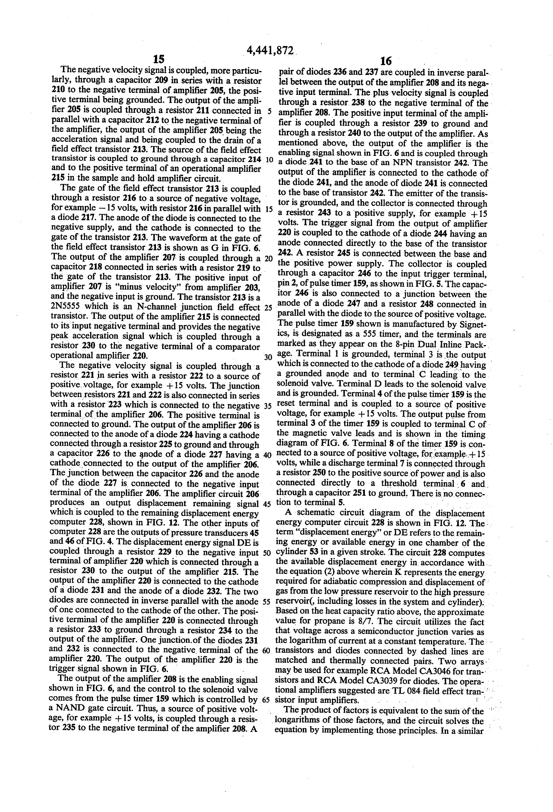
The output of the amplifier 207 is coupled through a 20 242. A resistor 245 is connected between the base and the positive power supply. The collector is coupled capacitor 218 connected in series with a resistor 219 to through a capacitor 246 to the input trigger terminal, the gate of the transistor 213. The positive input of amplifier 207 is "minus velocity" from amplifier 203, pin 2, of pulse timer 159, as shown in FIG. 5. The capac and the negative input is ground. The transistor 213 is a itor 246 is also connected to a junction between the anode of a diode 247 and a resistor 248 connected in 2N5555 which is an N-channel junction field effect 25 parallel with the diode to the source of positive voltage. transistor. The output of the amplifier 215 is connected The pulse timer 159 shown is manufactured by Signet to its input negative terminal and provides the negative peak acceleration signal which is coupled through a ics, is designated as a 555 timer, and the terminals are resistor 230 to the negative terminal of a comparator marked as they appear on the 8-pin Dual Inline Pack operational amplifier 220. 30 age. Terminal 1 is grounded, terminal 3 is the output The negative velocity signal is coupled through a which is connected to the cathode of a diode 249 having resistor 221 in series with a resistor 222 to a source of a grounded anode and to terminal C leading to the positive voltage, for example +15 volts. The junction solenoid valve. Terminal D leads to the solenoid valve between resistors 221 and 222 is also connected in series and is grounded. Terminal 4 of the pulse timer 159 is the with a resistor 223 which is connected to the negative 35 reset terminal and is coupled to a source of positive terminal of the amplifier 206. The positive terminal is voltage, for example -- 15 volts. The output pulse from connected to ground. The output of the amplifier 206 is terminal 3 of the timer 159 is coupled to terminal C of connected to the anode of a diode 224 having a cathode the magnetic valve leads and is shown in the timing connected through a resistor 225 to ground and through diagram of FIG. 6. Terminal 8 of the timer 159 is con a capacitor 226 to the anode of a diode 227 having a nected to a source of positive voltage, for example+ 15 cathode connected to the output of the amplifier 206. volts, while a discharge terminal 7 is connected through The junction between the capacitor 226 and the anode a resistor 250 to the positive source of power and is also of the diode 227 is connected to the negative input connected directly to a threshold terminal 6 and terminal of the amplifier 206. The amplifier circuit 206 through a capacitor 251 to ground. There is no connec produces an output displacement remaining signal 45 tion to terminal 5. . .. . . which is coupled to the remaining displacement energy A schematic circuit diagram of the displacement computer 228, shown in FIG. 12. The other inputs of energy computer circuit 228 is shown in FIG. 12. The . computer 228 are the outputs of pressure transducers 45 term "displacement energy' or DE refers to the remain and 46 of FIG. 4. The displacement energy signal DE is ing energy or available energy in one chamber of the coupled through a resistor 229 to the negative input 50 cylinder 53 in a given stroke. The circuit 228 computes terminal of amplifier 220 which is connected through a the available displacement energy in accordance with. resistor 230 to the output of the amplifier 215. The the equation (2) above wherein Krepresents the energy output of the amplifier 220 is connected to the cathode required for adiabatic compression and displacement of of a diode 231 and the anode of a diode 232. The two gas from the low pressure reservoir to the high pressure diodes are connected in inverse parallel with the anode 55 reservoir(, including losses in the system and cylinder). of one connected to the cathode of the other. The posi Based on the heat capacity ratio above, the approximate tive terminal of the amplifier 220 is connected through value for propane is 8/7. The circuit utilizes the fact a resistor 233 to ground through a resistor 234 to the that voltage across a semiconductor junction varies as output of the amplifier. One junction.of the diodes 231 the logarithm of current at a constant temperature. The and 232 is connected to the negative terminal of the transistors and diodes connected by dashed lines are amplifier 220. The output of the amplifier 220 is the matched and thermally connected pairs. Two arrays trigger signal shown in FIG. 6. may be used for example RCA Model CA3046 for tran The output of the amplifier 208 is the enabling signal sistors and RCA Model CA3039 for diodes. The opera shown in FIG. 6, and the control to the solenoid valve tional amplifiers suggested are TL 084 field effect tran comes from the pulse timer 159 which is controlled by 65 sistor input amplifiers. . a NAND gate circuit. Thus, a source of positive volt The product of factors is equivalent to the sum of the age, for example -- 15 volts, is coupled through a resis longarithms of those factors, and the circuit solves the tor 235 to the negative terminal of the amplifier 208. A equation by implementing those principles. In a similar
Page 22
manner, the exponents are obtained by multiples of the the transistor 275 and the positive input terminal of the logarithms. amplifier 274. A capacitor 283 is coupled between the The displacement signal is coupled through a resistor emitter and collector of the transistor 282, and the emit 256 to the collector of an NPN transistor 257, the emit ter is also coupled through the anode of a diode 284 to ter of which is coupled to the output of an operational the output of the amplifier 281. The output of the ampli amplifier 258. A capacitor 259 is connected across the fier and the cathode of the diode 284 are connected emitter and collector of the transistor 257, and the col together and with a resistor 285 whose opposite end is lector of the transistor is also connected to the negative connected to the negative input terminal of the ampli input terminal of the amplifier 258, the positive terminal fier. 274 and to the collector of the transistor 275. The being grounded. The emitter of the transistor 257 is O remainder of the circuit generates a temperature sensi connected to the emitter of an NPN transistor 260 tive reference voltage which contributes to the compu which is matched to transistor 257. The collector is tation for the factor K in the equation for displacement connected to the negative input terminal of an opera energy, DE. A source of positive voltage, for example tional amplifier 261, the positive terminal of which is -- 15 volts, is coupled through a resistor 286 to the grounded. The output of the amplifier 261 is coupled 15 negative input terminal of an operational amplifier 287 through a resistor 262 to its negative input terminal. The having a grounded positive input terminal, the negative output of the amplifier 261 is the displacement energy terminal also being connected to the collector of an signal. The circuit within the dashed line 263 is a differ NPN transistor 288 which is matched with the transis ential antilog converter and multiplier which is re tor 266. The base of the transistor 288 is grounded, a peated for each valve control circuit. Two such circuits capacitor 289 is connected between the emitter and are required, one for each valve control circuit. The collector of the transistor 288, and the emitter is con remainder of the computer circuit is used for both nected to the output of the amplifier 287 and the base of valves. the transistor 260.
The low pressure signal is coupled through a resistor The electronic circuits just described are powered by 264 to the negative input terminal of an operational 25 rechargeable batteries (not shown) kept charged by amplifier 265 having a grounded positive terminal. The photovoltaic array 40 of FIG. 2. Power supply connec negative terminal is also coupled to the collector of a tions must be made to the operational amplifiers and are transistor 266 having an emitter coupled directly to the not shown in the schematics.
base of the transistor 257. A capacitor 267 is connected The energy conversion system according to the pres between the emitter and collector of the transistor 266, 30 ent invention, as described above, thus, can permit a and the base of the transistor is grounded. The emitter wind turbine to drive a reciprocating piston compressor of the transistor 266 is connected to the anode of a diode efficiently with the compressor pumping refrigerant 268, and the cathode of the diode 268 is connected to gases. The gas lines can belong, so that heat sources and the output of the amplifier 265 which is also coupled to sinks can be remote from the wind turbine and compres a test point terminal indicated as TP. A trimming poten 35 sor. Power transmission is effectively the fluid power tiometer 269 has a fixed portion connected at one end to represented by refrigerant flow in the pipes. The insu a positive voltage source, for example + 15 volts, and at lated pipelines may also be regarded as heat pipes in an the other end to a negative voltage, for example - 15 actively-driven heat pump system. Pipe runs are limited volts. The tap on the potentiometer is connected by flow losses and heat transfer through the pipe insula through a resistor 270 to the base of an NPN transistor tion. Maximum runs are on the order of a few hundred 271 and through a resistor 272 to ground. The collector yards for small systems (twenty-foot diameter wind of the transistor 271 is connected to the negative input turbines) and increase with system scale. terminal of the amplifier 265 and to the collector of the Except for the long-distance pipelines and separation transistor 266. The low pressure signal is also coupled of system components, the basic refrigerant circuit con through a resistor 273, equal in value to the resistor 264, 45 figuration is conventional and used in many commercial to the negative input terminal of an operational ampli applications. High-pressure gas travels from the com fier 274. The collector of an NPN transistor 275 is con pressor to the condenser, where it gives up heat on nected to the negative input terminal of the amplifier condensing. In this system, warm water enters and be 274. The emitter is connected to a series of six diodes comes the heat carrier as it becomes exiting hot water. indicated at 276, the emitter being connected to the 50 Refrigerant condensate flows through an uninsulated anode of the first diode with each cathode connected to pipeline to the evaporator. A float valve meters high an anode. A capacitor 277 is connected between the pressure refrigerant liquid into the low pressure side. emitter and collector of the transistor 275. The emitter The evaporator is a refrigerant boiler. Water is again of the transistor 271 is connected to the collector and the heat transfer medium, as warm water enters and is base of a transistor 278, which is matched with the 55 chilled to exit as cold water. In a heating system, the transistor 275. The emitter is connected to a series of six "warm' water may be cool ground water serving as a diodes 279 which are pairwise matched with the diodes heat source. Refrigerant evaporates, absorbing heat 276 and connected in series with each other in the same from the water, and the low pressure refrigerant gas manner as the diodes 276 with the cathodes of the last returns to the compressor to become high pressure gas two diodes connected together and to the output of the once again.
amplifier 274. As previously described and shown in FIG. 2, the The high pressure signal is coupled through a resistor wind turbine blades drive a cranklinked to a shaft going 280 to the negative input terminal of an operational to a spherical bearing. A linear ball bushing constrains amplifier 281, the positive input terminal of which is the shaft below to a linear reciprocating motion. Shaft grounded. The negative input terminal of the amplifier 65 velocity is sensed by a velocity transducer which sends 281 is also connected to the collector of an NPN transis a signal to the electronic control circuit. The compres tor 282 which is matched with the transistor 271 and has sor cylinder draws gas from the two valve assemblies a grounded base and an emitter connected to the base of from the low pressure reservoir and sends that gas to
Page 23
4,441,872 r
the high pressure reservoir. The reservoirs absorb pull valve, except that the velocity signals --vel. and -vel. sations in the gas motion from the compressor reducing are interchanged. The output of the velocity transducer , conversion of gas motion to acoustic waves traveling is supplied to an amplifier, and the amplified velocity: along the pipelines. signal is +vel. and is inverted to give-vel. The -vel. The high pressure reservoir serves an important heat signal undergoes band limited differentiation (the cir ing function. In dead calm periods when ambient termp-: cuit integrates at high frequencies) to yield an accelera erature is very low, refrigerants could potentially con tion signal. A non-inverting comparator driven, by the dense in the compressor, diluting and washing away -vel. signal provides a timing waveform whose posi lubricants. To prevent this, first the compressor is nor tive transition causes a quick sampling of the negative mally returned to the low pressure line. Thus, conden 10 going peak of acceleration to obtain acceleration at the. sation in the compressor can only begin in the vicinity beginning of the compression stroke. This acceleration of the pressure-determining temperature of the evapora is proportional to the square of angular velocity of the tor. The high pressure reservoir is held at the condenser turbine and determines the desired energy threshold for temperature by heat-pipe. action, with refrigerant gas valve closure on the compression stroke to follow im condensing in the reservoir, liberating heat, and flowing 15 mediately. The -vel. signal is integrated to give a posi back as condensate. The heated reservoir shares, the tive position, or displacement, signal, and the displace insulating jacket with the compressor cylinder keeping ment signal is reset to just above zero at the end of each that cylinder warm. As long as heat storage maintains compression stroke so that the voltage represents dis condenser temperature somewhat above evaporator placement remaining to the end of the compression temperature (cold storage in ice or frozen solutions 20 stroke (including "dead volume' that is not displaced). would accomplish the same purpose), condensation in A non-linear function generator accepts the pressure the cylinder is avoided. . *, transducer output voltages and yields a voltage propor The electronic control circuit triggers the two mag tional to compression energy per unit volume. This netic valves. Electric power for the control comes from measure has the physical units of pressure. The energy a photovoltaic array (PVA) and is stored in recharge 25 density is multiplied by displacement volume to yield a able batteries in the control box. The photovoltaic array "Displacement Energy', or "DE" signal. When the serves as an "optical isolator' for the electronics per positive "Displacement Energy” signal crosses the mitting a complete package with no insulated wires magnitude of the negative acceleration magnitude sig penetrating the conductive Faraday cage formed by the nal, the inlet valve is usually tripped shut. The valve is housing and a screen over the photovoltaic array. This 30 not tripped at very low turbine speed. A second com design avoids ground paths that would attract energy parator generates a trigger-enable time window begin from lightning discharges through electronics. It would ning shortly after the beginning of the compression be permissible to use part of the wind-derived mechani stroke and ending shortly before the end of the stroke. cal energy of the system to generate electricity, though This window begins and ends as compression velocity for the very small scale needed, the photovoltaic ap 35 exceeds and then falls below a fixed bias. If angular proach is simpler than designing a low-power generator velocity is too low, the enable window has ended (or and linkages. - never begun) before the "Displacement Energy' As previously described and shown in FIG. 3, the threshold transition takes place, and then triggering is piston sends gas back and forth through the normally prevented. At very high turbine speeds, the accelera open low pressure inlet valves, which double as bypass tion magnitude signal will always exceed the "Displace valves. A pulse of current to the coil around the mag ment Energy' threshold voltage such that maximum netic core extending down in front and behind the plane displacement is not enough to satisfy the optimum load of the drawing causes the piece of magnetic material in ing criterion. In this case, the beginning of the trigger the end of the inlet reed valve member to move to the enable window, just after the beginning of the compres O-ring valve seat adjacent the low pressure outlet of the 45 sion stroke, times the triggering of the timer and subse valves. The valve body or housing is cut from three quent closure of the inlet valve. Triggering is always pieces of non-magnetic material. The pieces are ma delayed slightly until there is some velocity in the inlet chined, coated with gasketing compound, and screwed valve to seat the inlet valve quickly, minimizing the together (screws not shown). When the inlet valve is energy needed to sustain a magnetic trigger pulse. closed magnetically, pressure buildup quickly secures 50 The non-linear energy function generator depends on the valve in closed position so that the magnetic pulse the heat capacity ratio of the refrigerant gas (y). The can be very brief. When cylinder pressure builds up and circuit of FIG. 12 is specifically devised for propane, a exceeds output reservoir pressure, the outlet reed valve refrigerant gas whose heat capacity ratio (y) is roughly 128, now no longer partially covered by the inlet reed 8/7. The circuit utilizes the fact that a semiconductor valve 127, opens to permit one-way exhaust flow. When 55 junction exhibits a logarithmic voltage/current charac compression is complete, falling cylinder pressure per teristic that can be used to generate powerfunctions and mits the inlet reed valve to reopen. Electrical energy to - products. The equation solved by the circuit appears operate the servo-valve is very low since most of the beneath the schematic. Note that a voltage representing energy comes from the gas flow. . . . one-times-the-logarithm of a current is generated by a The velocity transducer is formed of a stationary coil single transistor, and seven-times-the-logarithm of a and a moving magnetic core that includes part of the current is generated by seven transistors, six of them reciprocating piston shaft. The voltage signal varies diode-connected, in series. The resulting sum of eight accurately in proportion to velocity. The transducer is logarithms is applied as a voltage to the string of eight commonly called a voice coil generator and is the coun transistors, which generate current equal to the expo terpart of the voice coil actuator used in loudspeakers 65 nential function of one-eighth the input sum. This cur except that the magnet moved instead of the coil. rent is the desired power function product, and the With respect to the electronic control circuit of FIG. linear term is subtracted at the output summing ampli 4, the lower part of the circuit is repeated for the second fier. Finally, the circuit generates the logarithm of the
Page 24
energy density current, sums this with the logarithm of said transformer means include electrically actuated displacement, subtracts a scaling logarithm, and ex relief valve means.
ponentiates to generate the final output. The detailed 4. The system of claim 1, wherein: circuit function will be clear to one skilled in the art of said fluid relief means include electrically actuated electronics. valve means for enabling energy transfer to said To indicate a few more concrete details of a particu load means, and transfer valve means responsive to lar energy conversion system of the present invention, said enabling valve means for transferring energy the specific energy conversion system described pumps from said source to said load means. heat from ground water at about 50 F. to aquaculture 5. A fluid energy conversion system, comprising: water varying from 60' to 90' F. Condenser refrigerant 10 (A) variable fluid energy source means; temperature must belimited to 105 F. to avoid exceed (B) variable load means;
ing the compressor cylinder's maximum pressure rating (C) transformer means responsive to said energy of 200 PSI. Excessive pressure in the high pressure source and load means, including means for deter reservoir may be used to inhibit valve triggering (not mining the relative energies associated with said shown in circuitry), isolating the compressor cylinder 15 load and source means for controlling the period from high pressure and preventing further heat pump during which said load and source means are cou ing. The compressor cylinder is a modified air cylinder pled together, substantially continuously to match of eight-inch diameter and four-inch stroke. This dis the impedances of said source and load means, such placement absorbs full output power at optimum match that substantially maximum energy transfer takes from a 20-foot diameter turbine up to a windspeed vary 20 place substantially continuously, ing from roughly 20 to 24 MPH, depending on system said transformer means including fluid relief means operating temperatures. Pipe surface area in both the for controlling said period and electronic control evaporator and condenser is about 40 square feet. This means, is sufficient to transfer roughly 100,000 BTU/HR, the said electronic control means having, means for maximum system output, with a temperature differen 25 sensing a selected parameter of said system, tial of 20 F. in both evaporator and condenser. means responsive to said sensed parameter for Inasmuch as the present invention is subject to many actuating said fluid relief means, and computer variations, modifications and changes in detail, it is means responsive to said sensed parameter for intended that all subject matter described above and computing said period during which said source shown in the accompanying drawings be interpreted as 30 and load means are coupled for transferring illustrative and not in a limiting sense. power from said source to said load means, I claim: - said computer means including 1. A fluid energy conversion system, comprising: means for computing the amount of energy (A) variable fluid energy source means; transferred from said source to said load (B) variable load means; 35 means;
(C) transformer means responsive to said energy means for predicting a desired level of energy source and load means, including means for deter transfer; and mining the relative energies associated with said means for terminating said period only if said load and source means for controlling the period energy transferred exceeds said level. during which said load and source means are cou 6. The system of claim 5, wherein: pled together, substantially continuously to match said transformer means include piston-actuated com the impedances of said source and load means, such pressor means.
that substantially maximum energy transfer takes 7. The system of claim 5, wherein: place substantially continuously, said transformer means include electrically actuated said transformer means including fluid relief means 45 relief valve means.
for controlling said period and electronic control 8. The system of claim 5, wherein: means, said fluid relief means include said electronic control means having, means for sens electrically actuated valve means for enabling en ing a selected parameter of said system, means ergy transfer to said load means, and responsive to said sensed parameter for actuating 50 transfer valve means responsive to said enabling said fluid relief means, and computer means respon valve means for transferring energy from said sive to said sensed parameter for computing said source to said load means, period during which said source and load means 9. A fluid energy conversion system, comprising: are coupled for transferring power from said (A) rotating energy source means driven by variable source to said load means, 55 fluid motion;
said computer means including (B) variable fluid load means; means for computing the amount of energy that (C) variable energy transformer means coupled be can be transferred during the remainder of a tween said source and load means; transformer cycle; (D) as a part of said transformer means, compressor means for predicting a desired level of energy means for conversion of rotational energy of said available from said source means; and source means into fluid energy of said load means, means for initiating said period only if said energy where said conversion of energy takes place during level available from said source means exceeds repetitive energy transfer cycles, which may over said amount. lap in time, and where the repetition frequency of 2. The system of claim 1, wherein: 65 said transfer cycles is in fixed proportion to the said transformer means includes piston-actuated com rotation speed of said source means; - pressor means. (E) as a part of said compressor means, variable fluid 3. The system of claim 1, wherein: relief means that can reduce the time duration of
Page 25
said transfer cycles, such that the amount of energy 13. The system of claim 9, wherein said specified transferred from said source means in one of said average energy transfer represents a specified combina tion transfer cycles can be reduced, such that the rota tion speed of said source means is allowed to be 5. ofinantheaverage over one or more of said transfer cycles past, higher than it would be in the absence of fluid of the energy transferred during the present uncom relief; pleted transfer cycle, and
(F) as a part of said transformer means, control means of a predicted average over one or more of said trans that regulate said relief means to achieve a desired fer cycles in the future.
range of rotation speeds in said source means, such 10 14. The system of claim 9, wherein:
that said source means can efficiently absorb and (A) said rotating energy source means is a water transfer the energy of said fluid motion; turbine;
(G) as a part of said control means, sensor means (B) said fluid motion driving said source is water responsive to one or more selected parameters of 15 (C)flowing said through an adjustable gate;
desired value of said specified ratio is fixed the operation of said system, such that the response for any given gate setting but is different for differ of said sensor means can potentially be used to ent gate settings; and compute approximately a specified ratio of the (D) said control means include means for adjusting square of the rotation speed of said source means to the operation of said control means such that said a specified average energy transfer from said 20 desired value, toward which said specified ratio is source means per transfer cycle; and caused to be corrected, can effectively be altered (H) as a part of said control means, computer means when said gate is adjusted, such, that substantially that use the response of said sensor means, and that maximum average power transfer can take place direct the regulation of said relief means, to affect for any given gate setting over a range of gate said time duration, thereby to affect said amount of 25 settings and for said range of conditions of said energy transferred and said range of rotation fluid motion and said load means, but where said speeds in said source means in such a way that said range of conditions may differ for different gate specified ratio of squared rotation speed to average settings.
energy transfer per cycle is caused to be corrected 30 15. The system of claim 9, wherein: (A) said rotating energy source means is a wind tur toward a desired value, said desired value being bine;
determined as a value that causes substantially (B) said desired value of said specified ratio is fixed maximum average power transfer from said source for any given air density but is different for differ means to said load means to take place for a range ent values of air density; and of conditions of said fluid motion and said load 35 (C) said control means include means for adjusting eaS the operation of said control means such that said 10. The system of claim 9, wherein said specified desired value, toward which said specified ratio is average energy transfer is an average over one or more caused to be corrected, can effectively be altered to of said transfer cycles in the past. fit different air density conditions, such that sub 11. The system of claim 9, wherein said specified stantially maximum average power transfer can average energy transfer represents the energy trans take place for any given air density condition over ferred during the present, uncompleted transfer cycle. a range of said air density conditions and for said range of conditions of said fluid motion and said 12. The system of claim 9, wherein said specified load means, but where said range of conditions average energy transfer represents a predicted average 45 may differ for different airk density conditions.
over one or more of said transfer cycles in the future.
Provenance
- Collection
- Cited prior art
- Original PDF
- patentimages.storage.googleapis.com →
- Filed
- 1981-04-29
- Pages
- 25
- Method
- pdftotext (the PDF's own text layer) + pdftoppm 300dpi page scans
- Source
- Google Patents bibliographic record
- Granted
- 1984-04-10
- Inventors
- Joseph B. Seale
- Transcribed from
- patentimages.storage.googleapis.com →