patent · US3559626
Apparatus and process for accumulating and concentrating heat energy
2 February 1971
Page 1 — bibliographic record
United States Patent 113,559,626 72) inventor Douglas R. Paxton 3.242.91 l 3/1966 Schroedter................... 42631st St., Newport Beach, Calif. 92660 1221406 21 Appl. No. 788,800 3,395,678 8/1968 Kochey, Jr.................... 1221406 22 Filed Jan. 3, 1969 Primary Examiner-Kenneth W.Sprague 45) Patented Feb.2, 1971 Attorney-Pastoriza & Kelly
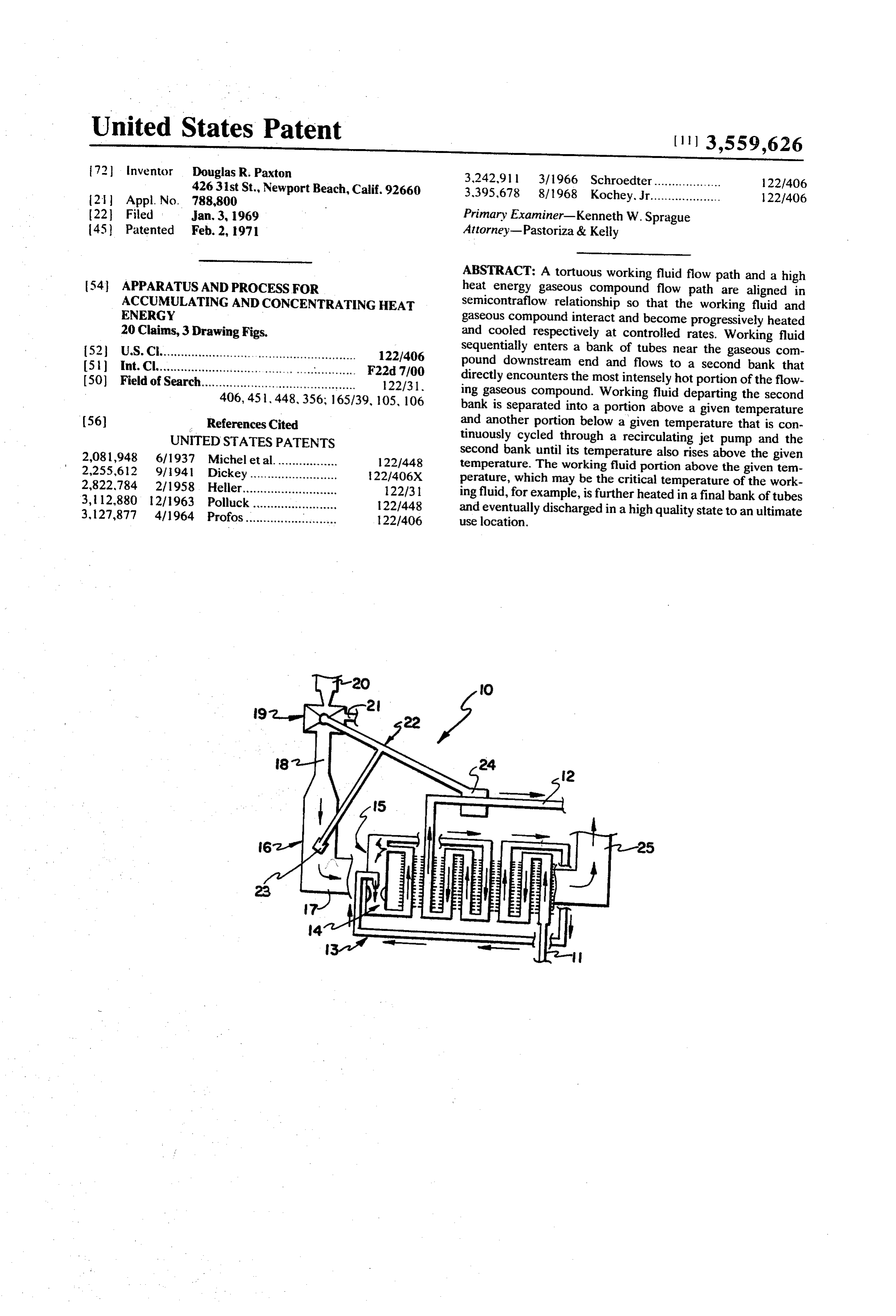
ABSTRACT: A tortuous working fluid flow path and a high 54 APPARATUS AND PROCESS FOR heat energy gaseous compound flow path are aligned in ACCUMULATING AND CONCENTRATING HEAT semicontraflow relationship so that the working fluid and ENERGY gaseous compound interact and become progressively heated 20 Claims, 3 Drawing Figs. and cooled respectively at controlled rates. Working fluid 52 U.S. Cl........................................................ 1221406 sequentially enters a bank of tubes near the gaseous com (51 Int. Cl............ ... F22d 7700 pound downstream end and flows to a second bank that (50) Field of Search............................................ 122/31 directly encounters the most intensely hot portion of the flow 406, 451,448,356; 165/39, 105, 106 ing gaseous compound. Working fluid departing the second bank is separated into a portion above a given temperature 56) References Cited and another portion below a given temperature that is con UNITED STATES PATENTS tinuously cycled through a recirculating jet pump and the 2,081,948 6/1937 Michel et al.................. 1221448 second bank until its temperature also rises above the given 2.255,612 9/1941 Dickey ......... 22/406X temperature. The working fluid portion above the given tem 2,822,784 2/1958 Heller.... 122/31 perature, which may be the critical temperature of the work 3, 12.880 12/1963 Polluck. 122/448 ing fluid, for example, is further heated in a final bank of tubes 3.127,877 4/1964 Profos. and eventually discharged in a high quality state to an ultimate
Page 2
Drawing sheet — no readable text.
Page 3
Drawing sheet — no readable text.
Page 4
APPARATUS AND PROCESS FOR ACCUMULATING AND Working fluid discharged from the second bank and which CONCENTRATING HEAT ENERGY is above the given temperature is passed to a third bank of This invention relates to a heat exchanger and more specifi tubes that is located physically between the first and second cally to a semicontraflow-type heat exchanger capable of sup banks and is protected from excessive heating by the recircu plying high quality working fluid while operating on a start and lation of working fluid through the second bank. Because the stop basis. recirculating jet pump constantly recirculates working fluid BACKGROUND OF THE INVENTION through the second bank, the mass flow rate of working fluid is greater through the second bank than through the first bank it is common practice to employ a contraflow type heat and third bank. Before entering the third bank the working exchanger for transferring heat energy from one flowing fluid 0. fluid is preferably passed through an intermediate bank of to another fluid flowing in an opposite direction. As the hotter tubes located physically between the first and third banks for fluid becomes progressively cooler, the colder fluid constantly stabilizing and controlling the working fluid temperature. absorbs heat and becomes progressively warmer. Frequently Coupled to the recirculating jet pump is a fluid separation the fluid being heated enters the contraflow heat exchanger as 15 chamber for diverting working fluid below the given tempera a liquid and departs as a gas. ture, which may be the critical temperature of the working A serious obstacle that conventional contraflow heat fluid for example, back to the recirculating jet pump and exchangers have been unable to overcome concerns conserv diverting working fluid above the given temperature in a ing energy and preventing hardware deterioration when the direction towards the third bank of tubes. Recirculation is ac heat exchanger is operated on an intermittent or start and stop 20 complished by a pressure differential established between basis. When hot gases are being routed in one direction and a greater working fluid pressure in a diffuser section of the recir fluid for absorbing heat from the gas is being flowed in the op culating jet pump and lower working fluid pressure in the fluid posite direction, the fluid ordinarily exits at a maximum con separation chamber. The pressure differential forces working stant temperature. When the fluid flow is abruptly terminated, fluid below the given temperature to recirculate through the then the heat energy from the gas can no longer be carried 25 second bank until its temperature rises above the given tem away so available heat energy from the gas boosts the tem perature. Preferably a spiral is formed on the interior perature of the now stationary fluid to an extremely high periphery of the fluid separation chamber and working fluid degree where catastrophic results can occur such as destruc egressing the second bank is tangentially injected against the tion of the heat exchanger itself. undersurface of the spiral in order to force the relatively Various approaches have been proposed for eliminating this 30 colder working fluid downwardly to the recirculating jet problem such as: pump.
1. immediately injecting cold liquid in the fluid discharge From a process standpoint the present invention involves end when the fluid flow is shut off; the steps of simultaneously flowing a high heat energy gaseous 2. dumping the hot gas into a cold sump; 35 compound and a working fluid along flow paths that intersect 3. dumping the extremely hot fluid into a cold sump; in semicontraflow relationship. The working fluid is preheated 4. providing a huge chamber or tank for the heat absorbing in a first bank of tubes and then flowed through a chamber to a fluid so that the fluid is characterized by a large thermal second bank of tubes. Effluent from the second bank is capacity and therefore can soak in great quantities of heat separated into portions above and below a given temperature. without appreciable temperature increases; and Working fluid above the given temperature is removed from 5. restricting the thermal capacity of the heat exchanger 40 the chamber to a third bank of tubes. Working fluid below the system to such low temperature limits that anticipated given temperature is recirculated through the chamber and temperature rises by the fluid cannot possibly attain dan second bank continuously until its temperature rises above gerous levels. In addition, these approaches can be com said given temperature. The recirculating flow serves to force bined such as by simultaneously injecting cold liquid and 45 working fluid through the second bank at a mass flow rate dumping hot gases. greater than that of the first bank and third bank. At all times All of the foregoing approaches are unsatisfactory in vary the gaseous compound is directed to flow successively into ing degrees because external systems must be employed or the contact with the second bank, third bank, and, then the first operational range of the heat exchanger must be restricted to bank.
narrow low temperature levels. Another disadvantage in 50 Preferably the temperature of working fluid discharged herent in conventional contraflow heat exchangers is their ina from the third bank is constantly sensed in order to automati bility to adequately control the temperatures of organic fluids cally regulate the mass flow rate of gaseous compound and which are very susceptible to thermal breakdown and decom hence heat quantity entering the system.
position.
55 BRIEF DESCRIPTION OF THE DRAWINGS
BRIEFSUMMARY OF THE INVENTION
The numerous benefits and unique aspects of the presentin
Briefly stated the present invention contemplates a com vention will be fully understood when the following detailed pact, easily operated apparatus with no moving parts, and, a description is studied in conjunction with the drawings, in process of for accumulating a high heat energy gaseous com which:
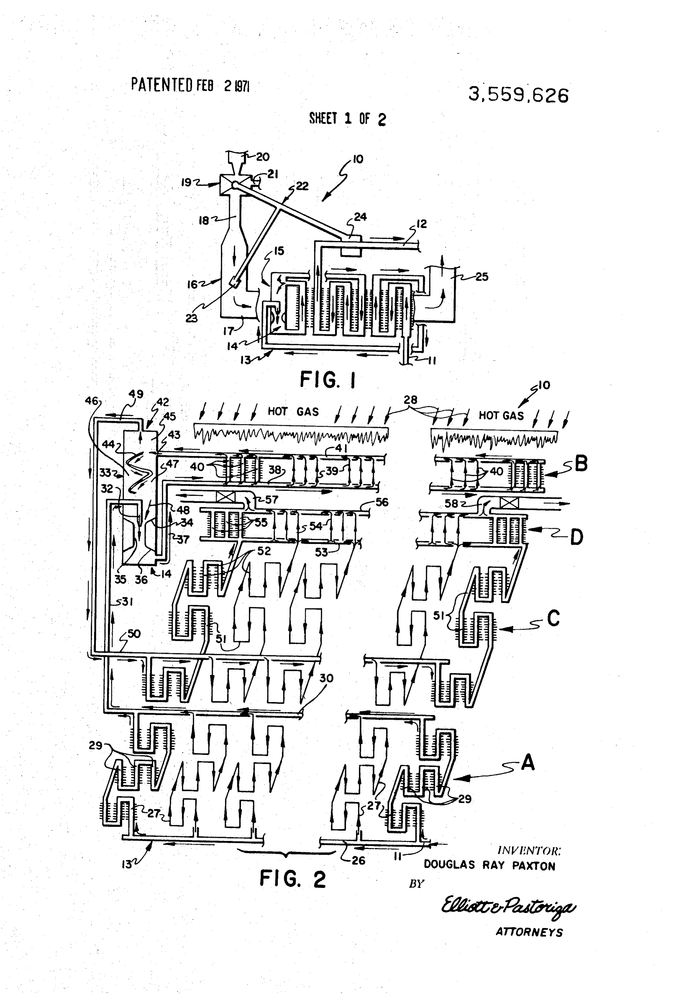
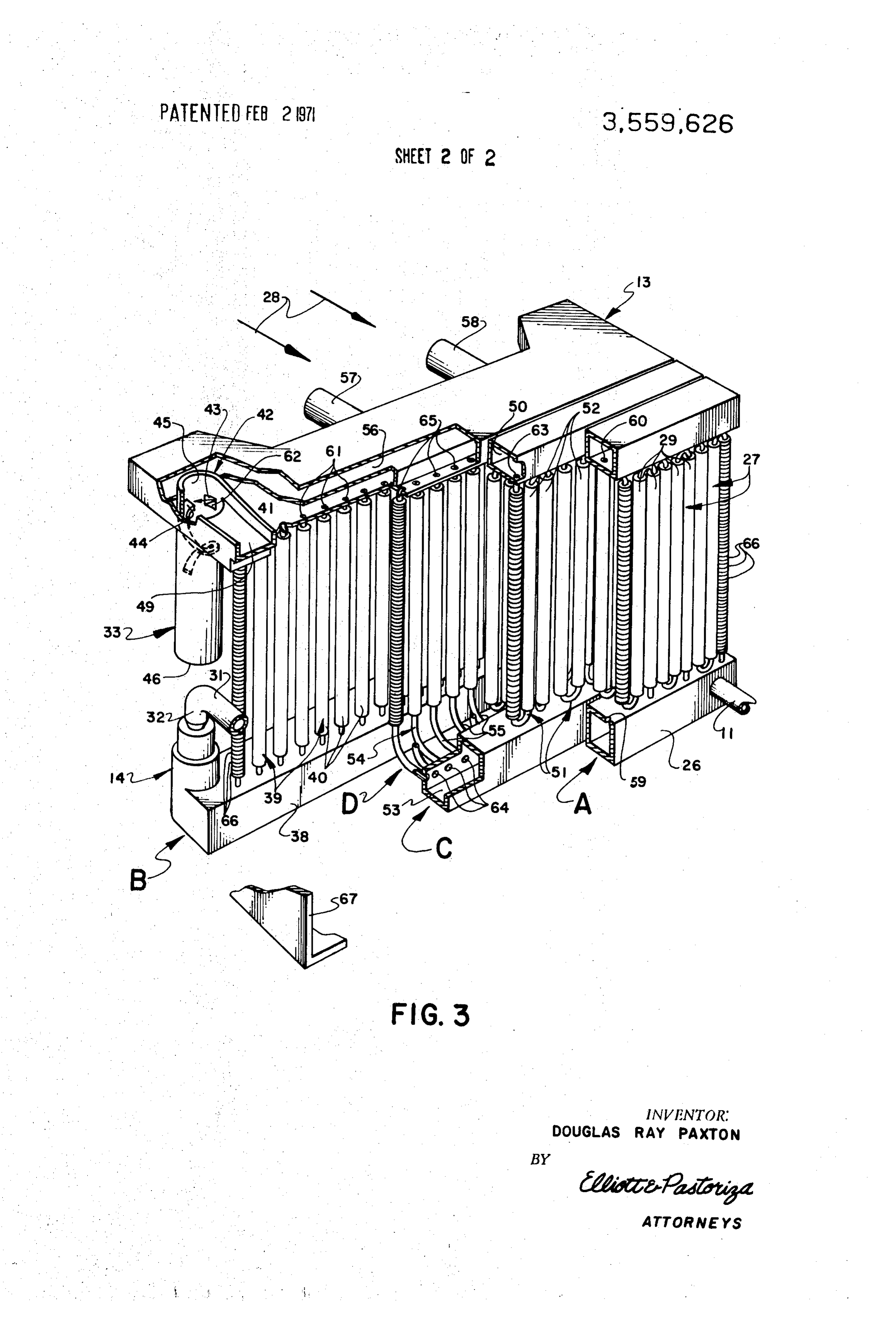
pound and concentrating it upon a working fluid. Flow paths 60 FIG. 1 is a schematic view showing the heatenergy accumu for the working fluid and gaseous compound are aligned in lator and concentrator system of the present invention; semicontraflow relationship so the working fluid becomes FIG. 2 is a flow diagram showing how the working fluid and progressively heated at a controlled rate while the gaseous gaseous compound flow paths are arranged in semicontraflow compound becomes progressively cooled. 65 relationship; and,
The apparatus includes a first bank of tubes for receiving FIG. 3 is a perspective partially sectional view showing im and preheating the working fluid and a second bank of tubes tor portant details of some components of heatenergy accumula located further upstream in the gaseous compound flow path and concentrator system.
than the first bank. Positioned between and arranged in com DETALED DESCRIPTION OF THE PREFERRED munication with the first and second banks is a recirculation 70 means, such as a recirculating jet pump. The recirculating jet EMBODIMENT pump is operated by working fluid for recirculating a segment Referring now to FIG. 1, a heat energy accumulator and of working fluid discharged from the second bank at a tem concentrator system 10 constructed in accordance with the perature below a given temperature back through the second. present invention is shown incorporated in one of numerous bank until it exceeds the given temperature. 75 possible assemblies in which it is important to raise a fluid to
Page 5
high temperature or supercritical temperature without the risk After working fluid has been routed from manifold 26 of thermal breakdown. As explained in copending U.S. Pat. through tubular clusters 27 it becomes discharged into an exit application filed on Oct. 13, 1968, and entitled "ENERGY manifold 30 and routed through a conduit 31 to recirculating CONVERSION SYSTEM AND PROCESS FOR GENERAT jet pump 14. Working fluid issues through a nozzle 32 into ING TORQUE, the system 10 may be used in various vehi recirculating jet pump 14 that is housed in a recirculation cles and other equipment that require generated torquc. Typi chamber 33. Recirculating jet pump 14 includes an entrance cal examples are conventional automobiles and other land throat 34 adjacent nozzle 32, an intermediate mixing section vehicles, helicopters, marine vehicles, heavy-duty equipment 35, and, a diffuser section 36. Diffuser section 36 com such as hoists and related article handlers, bulldozers and municates with a conduit 37 through which working fluid earth movers, hotel air conditioning and refrigeration systems 10 is flowed to a bank of tubes B.
as well as other related stationary total energy systems. Bank of tubes B incorporates a plurality of tube clusters 39 Heat energy accumulator and concentrator system 10 has each having three individual tubes 40 aligned in parallel with an inlet 11 for admitting working fluid at a lower temperature one another. Tubes 40 are shown in clusters 39 merely for and an exit 12 for discharging the working fluid at a predeter 15 comparison purposes so it can be clearly demonstrated that mined higher temperature and distributing the working fluid bank B has more fluid inlets and outlets for the working fluid in this state to an ultimate use location such as a drive than bank A. After being heated by the gaseous compound to mechanism (not shown) arranged to convert thermal energy a high energy level the working fluid is passed through an exit into mechanical energy. System 10 includes a heat exchanger manifold 41 to a fluid separation chamber 42 of circular cross 13 coupled in fluid communication to a recirculating jet pump 20 section. As indicated by arrow 43 working fluid from manifold 14. Recirculating jet pump 14 is oriented in fluid communica 41 is directed tangentially to the undersurface of a spiral 44 in tion with and coupled to the base of a fluid separator 15. As corporated on the interior surface of fluid separation chamber shall be fully explained, separator 15 operates to divide work 42. Spiral 44, that is wound through two or more helical turns, ing fluid into two segments, one segment of which has a tem functions to assist in diverting working fluid above a given perature below a given temperature while the other fluid seg 25 temperature or below a given density to a hot fluid separation ment has a temperature exceeding the given temperature. zone 45 and working fluid below the given temperature or Heat energy accumulator and concentrator system 10 is ar above a given density to a cold fluid separation zone 46. ranged adjacent a heat generating chamber 16 having an exit While the fluid guided or diverted into zone 45 and 46 may section 17 through which a high heat energy gaseous com be vapor and liquid respectively, this type of segregation pound is distributed to system 10. Heat generating chamber 30 predicated upon differences in fluid state is not necessary and 16 includes an inlet section 18 joined to a mixing chamber 19 both may be substantially compressible or substantially non that accepts oxidizer such as ambient air from an oxidizer line compressible fluids. Intermediate section 47 of recirculation 20 and fuel from a fuel line 21. The oxidizer and fuel charges chamber 33, which is a portion of separation chamber 42, is issuing through lines 20 and 21 strike or impinge upon one constantly occupied with working fluid. Therefore it can be another in mixing chamber 19 where they become sufficiently 35 seen that when centrifugal force drives relatively colder work commingled before being channeled into heat generating ing fluid under spiral 44 it becomes thrust downwardly chamber 16. towards recirculating jet pump 14 so relatively hotter working A monitor responsively coupled with mixing chamber 19 fluid must rise into hot fluid separation zone 45. and heat energy accumulator and concentrator system 10 in The colder working fluid that is swirled downwardly cludes a sensor 23 for sensing the temperature of the high heat 40 through recirculation chamber 33 and returned to recircula energy gaseous compound flowing through heat generating tion jet pump 14, as indicated by arrow 48, is continuously chamber 16 and, in response to this temperature, regulating recirculated until its temperature exceeds the predetermined the fuel to air ratio. given temperature. Upon this occasion, the particular slug of In ordinary heat exchange systems the amount of heat in working fluid will be transmitted through a bypass conduit 49
troduced into the heat exchange system is controlled by to manifold 50 associated with bank of tubes C. changes in pressure. In contrast with this conventional ap The jet of working fluid streaming through nozzle 32 draws proach another sensor 24 is arranged to sense temperature of fluid from chamber 33 into entrance throat 34. The mass flow the working fluid discharged from heat exchanger 13. In ratio of the driving fluid entering throat 34 from nozzle 32 and response to this temperature sensed by sensor 24 the mass 50 the driven fluid entering throat 34 from chamber 33 may be flow rate of the oxidizer and fuel ingredients and hence the for example of the order of one to two. The driving fluid of the quantity of heat added to the system is thus regulated. Gase jet flow entrains a portion of the driven fluid and increases its ous compound eventually exits through an exhaust line 25. acceleration as the two fluids travel through mixing section Referring now to FIG. 2, heat energy accumulator in con 35. The combined kinetic energy of the two fluids is converted centrator system 10 is illustrated in flow diagram or schematic 55 to increase potential energy by reason of distortion in diffuser form. Working fluid is transmitted from inlet 11 to a manifold section 36 so that the fluid pressure at the base of chamber 33 26 that distributes the working fluid to a bank of tubes A. As is significantly greater than the pressure of the working fluid in shall be fully explained, the working fluid passes sequentially the top of chamber 33. As a consequence, working fluid is through banks of tubes A, B, C, and finally D. Bank of tubes A pushed through manifold 38 and tubes 40 because of the pres includes plural tube clusters 27 that are aligned in rows, in a 60 sure differential.
direction parallel to the flow path of the high heatenergy gase One way to increase the percentage of driven fluid entering ous compound indicated by arrow 28, and in columns aligned recirculation jet pump 14 is to increase the distance between perpendicularly to gaseous compound flow path 28. Each tube the tip of nozzle 32 and location of the smallest diameter of cluster 27 has three serially aligned individual tubes 29. The throat 34. The mixing efficiency of the two fluids can be in important purposes for the particular tubular cluster and in 65 creased by enlarging the length of mixing section 35 with dividual tube alignment as well as the structural relationships respect to its diameter. The pressure differential may also be between banks of tubes A, B, C and D will be fully described increased by increasing the final exit area of diffuser section as the description of the present invention proceeds. 36, or the nozzle orifice may be reduced to supply more As employed to explain the present invention the term energy by increasing the fluid velocity.
semicontraflow is intended to mean that while the gaseous 70 Since individual tubes 29 of bank A constitute only one compound and working fluid travel in flow paths generally third of the flow paths that are constituted by individual tubes aligned in opposite directions the paths may be aligned in the 40 of bank B it can be understood that, if recirculation jet same directions for relatively short segments. The semicon pump 14 were eliminated the total mass flow rate through traflow system of the present invention may also include cross banks A and B would be identical but the mass flow rate flow segments. 75 through individual tubes 29 would be three times greater than
Page 6
S 6 that through individual tubes 40. It is important to note at this columns aligned substantially perpendicular to the gaseous point that the recirculation jet pump 14 can be modified or ad compound flow path 28. Tube clusters 27 are also arranged in justed as indicated in the previous paragraph so that not only plural rows aligned substantially parallel to the gaseous com can the mass flow rate in bank B exceed that of bank A but the pound flow path. After egressing tube clusters 27 through exit individual mass flow rates of tubes 40 can also surpass that of 5 ports 60, the working fluid is routed to conduit 31 that ter individual tubes 29. The reasons for flowing working fluid at a minates in nozzle 32 which injects working fluid into the relatively high mass flow rate through bank B and its in throat section of recirculating jet pump 14. dividual tubes will be fully explained as the description of the The working fluid flows through bank B and exits by ports present invention proceeds. 61 to a manifold 41. A stream of working fluid indicated by in order to permit fluid separation chamber 42 to divide O arrow 43 is injected tangentially from a manifold 41 through a relatively hot and cold working fluid into zones 45 and 46 discharge port 62 into fluid separation chamber 42. Discharge respectively, recirculation chamber 33 remains entirely filled port 62 is positioned so that stream 43 impinges upon the un with working fluid. When the velocity of working fluid issuing dersurface of spiral 44 in order to force colder working fluid from exit manifold 41 becomes greatly diminished upon enter against the interior periphery of the fluid separation chamber ing fluid separation chamber 42, relatively colder working 15 42 and downwardly to jet pump 14. As previously mentioned, fluid sinks and automatically displaces relatively warmer the colder fluid travels down the outside of chamber 42 working fluid which is forced upwardly. It can be seen there beneath spiral 44 and warmer fluid therefore becomes auto fore that if spiral 44 were eliminated, the separation of fluid matically displaced upwardly through the center of chamber based on temperature differences could still be effected 42 and passes outwardly through bypass conduit 49. The although not as rapidly as when spiral 44 is employed. Spiral colder working fluid is continuously recirculated through 44 promotes a swifter separation of the relatively hot and cold bank B by jet pump 14 until it as also exceeds the given tem fluids by accepting working fluid aimed in a tangential perature.
direction 43 and retaining the colder fluid beneath its under Working fluid heated to the given temperature flows from surface. 25 bypass conduit 49 to bank C and enters tube clusters 51 In order to vary the given temperature that distinguishes through inlet ports 63 arranged in communication with between the relatively hot and cold working fluid, the width of manifold 50. The tube clusters 51 of bank C are aligned in spiral 44 can be adjusted. For example by widening the width three columns arranged substantially perpendicular to the of spiral 44, more working fluid will be routed for recircula gaseous compound flow path 28. Tube clusters 51 are also tion and therefore only working fluid above an increased tem 30 aligned in rows substantially parallel to gaseous compound perature will be permitted to flow through conduit 49. Also flow path 28. As in the case of tube clusters 27 of bank A, the the jet pump flow rate can be increased. tube clusters 51 of each row are arranged in series. Working fluid at the desired given temperature is flowed to Working fluid passes from manifold 53 to bank D by inlet manifold 50 for distribution through tube clusters 51. As in ports 64. As in the case of tubes 40 of bank B, the tubes 55 of the case of tube cluster 27 of bank of tubes A, tube clusters 5 35 bank D form a single column aligned perpendicularly with are aligned in rows parallel with gaseous compound flow path gaseous compound flow path 28. In contrast with the in 28 and in column perpendicular to gaseous compound flow dividual tube tubes of banks A and C the individual tubes of path 28. Individual tubes 52 are arranged in series. banks B and D are aligned in parallel with one another. It Working fluid is driven to manifold 53 of bank of tubes D 40 should be noted that the individual tubes of bank A and bank for distribution to tube clusters 54. The individual tubes 55 of Care arranged vertically to flow working fluid in alternating tube clusters 54 conduct the working fluid into an exit upwardly and downwardly patterns. As shown in both FIG. 1 manifold 56 which in turn delivers the working fluid to a pair and FIG.3 the vertically aligned tubes of bank D flow working of exit conduits 57 and 58. Tubes 55 are also shown in clusters fluid in a direction opposite to the direction through which the 54 merely for comparison purposes so it can be demonstrated immediately adjacent tubes of bank Cflow the working fluid. that banks B and D each have more working fluid inlets and 45
The reason for causing the individual tubes of banks A, C, outlets than banks A and C. Optionally much the same effect and D to thus periodically or alternately flow working fluid in would be achieved by employing the same number of fluid in reverse directions is to achieve a high heat transfer efficiency lets and outlets in banks B and D but dimensioning their tubes by substantially uniformly distributing thermal energy of the with larger diameters than those defined by the tubes of banks 50 gaseous compound to the working fluid. If the individual tubes A and C. It is important to note that the total cross-sectional were not arranged to substantially uniformly accept heat from area of the respective banks is one of the important factors in the gaseous compound, then hotter gaseous compound would determining the velocity of working fluid through the in become concentrated upon particular portions of the in dividual tubes of the banks. dividual tubes and gaseous compound exhausted from heat Exit conduits 57 and 58 may for example deliver the work 55 exchanger 13 would then be divided into hotter and colder ing fluid in its now predetermined optimum state to zones. Inefficiency would be proportional to the disparity of mechanisms for generating mechanical energy. the temperatures in these two zones. The banks of tubes A, B, C, and Dare structured to sequen Thus high efficiency is attained by, in essence, arranging the tially treat flowing working fluid in such a way that it is gradu individual tubes so that a high heat transfer capability is main ally transformed to a predetermined high thermal energy state. 60 tained throughout the system and the gaseous compound is Bank of tubes A functions primarily to preheat entering work forced to liberate heat substantially uniformly and exit from ing fluid at a steady rate. Bank of tubes B operates to quickly heat exchanger 13 without zones of substantial temperature absorb heat from the gaseous compound at a rate sufficient to differences. With regard to attaining this desired uniform heat prevent destruction or melting of individual tubes 40 and 55 distribution it should be noted that the individual tubes. while also preventing degradation and decomposition of the 65 rather than being aligned vertically, could be aligned horizon working fluid. Bank of tubes Cis intended to stabilize the tem tally or at any desired inclination.
perature of the working fluid by either yielding heat energy to The individual tubes 55 of bank D are aligned vertically for a or extracting it from the gaseous compound. Bank of tubes D purpose to be described. Working fluid heated to the optimum serves to raise the working fluid temperature and furnish desired temperature flows through exit ports 65 into manifold working fluid in a high quality state to exit conduits 57 and 58. 70 56 and outwardly to conduits 57 and 58. Referring now to FIG. 3, working fluid entering heat The density, i.e., number per unit area, of the individual exchanger 13 through inlet 11 first passes through manifold tubes of the various banks may be constant or variable. Their 26. The working fluid passes through inlet ports 59 into the spacing may be tighter or wider for columns than for the rows. first individual tubes 29 of three serially aligned tube clusters One factor dictating the tube density and desirability of incor 27. The tube clusters 27 of bank A are arranged in three 75 porating or excluding heat conducting fins 66 on the tubes is
Page 7
predetermined by the impelling power of a blower, for exam hot gaseous compound. It is contemplated that when substan ple, used to push the gaseous compound through its flow path tial recirculation activity comes to a natural halt, sufficient 28. As the blower power is increased, the density and percent time will have elapsed to reduce the heat content of the gase age of finned tubes may also bc increased to maximize heat ous compound below the danger level. By distributing heat transfer efficiency. evenly from the gaseous compound throughout a large seg The tortuous flow path of the working fluid is defined by ment of the working fluid, this available heat in the gaseous heat exchanger 13 and recirculating jet pump 14. The flow compound is prevented from being concentrated upon a rela path 28 of the gaseous compound is defined primarily by the tively small portion of working fluid at the instant that spaces between adjacent individual tubes of banks A, B, C, and 10 discharge is stopped.
D and a surrounding container 67. Container 67 that encloses Some organic fluids must be heated at a more gradual a portion of heat exchanger 13 is a thin sheet metal duct rate when below , their critical temperatures than when layered with insulation to prevent escape of heat by radiation above their critical temperatures or else thermal breakdown or conduction. will result. When these organic fluids are forced to absorb heat Heat exchanger 13 is of general rectangular block configu 15 at a harmfully high rate, under conditions where local hot ration and, as can be fully understood now that the structure spots are engendered, they tend to break down into undesira of the present invention has been fully described, includes no ble constituents incapable of being reunited. Some of the con moving parts. Banks B, D, C, and A are arranged successively stituents fail to vaporize while others fail to condense and in an upstream to downstream direction with respect to the some constituents exist as solids that are deleterious to the gaseous compound flow path 28 so that the temperature of 20 system efficiency. These constituents may also form acids working fluid can be gradually increased as working fluid is capable of attacking and destroying various container materi moved along its flow path. als.
OPERATION A related problem with some organic fluids is that portions above the critical temperature cannot be heated to high tem
Keeping the above construction in mind it can be un 25 peratures while in contact with portions below the critical derstood how many of the previously described disadvantages temperature or else thermal breakdown may occur in the fluid of conventional contraflow heat exchangers are overcome or of subcritical temperature. Supercritical temperature fluid substantially eliminated by the present invention. must be separated from the subcritical temperature fluid be For the purpose of explaining its operation, the heat energy 30 fore its temperature is raised to a higher level. accumulator and concentrator system 10 is assumed to be in For purposes of explaining the operation of the present in corporated in an environment where the heat transfer action vention it is assumed that the working fluid is one of these or between the gaseous compound and working fluid is to be at ganic fluids prone to thermal breakdown under conditions least occasionally started and stopped. outlined above. Fluid separation chamber 42, in this situation, Fresh charges of working fluid entering the system through 35 would be arranged to divert working fluid above critical tem inlet 11 are preheated in bank A whose individual tubes 29 are perature to bypass conduit 49 in order to separate it from rela arranged to experience a mass flow rate sufficient to prevent tively cooler working fluid below the critical temperature. As the working fluid from stagnating and thermally decomposing. has been previously explained the working fluid temperature The most intense heat of the gaseous compound discharged through is gradually raised at a controlled rate while flow is occuring from heat generating chamber 16 is encountered by bank B. 40 when flowbanks is
A and B and is prevented from sharply rising abruptly stopped due to the recirculating action
Working fluid flowing through individual tubes 40 of bank B, at a relatively high mass flow rate. rapidly absorbs heat developed in part by jet pump 14. Inasmuch as bank B includes more fluid inlets and outlets from the gaseous compound to prevent components of bank B and bank D from melting or weakening. Relatively high tem than bank A and its individual tubes 40 are arranged in parallel perature working fluid passing through bank B is separated 45 to define much shorter flow paths than those defined by in out at short intervals in order to prevent the working fluid fluid dividual tubes 29 of bank A, it can be understood that working from attaining undesirable high temperatures. The relatively to passing through bank B is relatively quickly transmitted high mass flow rate through bank B, which is greater than that ingfluid separation chamber 42 and is prevented from becom through either banks A, C, or D, is caused by recirculating jet that workingtofluid heated a dangerous level. Thus bank B is structured so recirculated therethrough is exposed to the pump 14 that continuously recirculates a segment of working 50 gaseous fluid below the given temperature discharged from bank B cant heatcompound but its for a sufficient duration to acquire signifi flow paths are sufficiently short so that the back through bank B until it also exceeds the given tempera working fluid has frequent opportunities to escape to fluid ture.
Merely physically interposing bank B between heat generat separation chamber 42. The working fluid is permitted to escape from separation chamber 42 through bypass conduit ing chamber 16 and final bank D would adequately protect 55 49 before it reaches a temperature which would tend to cause bank D only during continuous working fluid flow condition. decomposition of the working fluid still below critical tem However, this arrangement alone, without recirculation, perature.
would fail to prevent overheating and possible destruction Working fluid diverted through bypass conduit 49 enters during sudden termination of working fluid flow through exit 60 bank C where it encounters gaseous compound with conduits 57 and 58.
The physical integrity of bank D is preserved during inter through bankheat diminished content. Initially working fluid flowing
C may liberate heat to the gaseous compound mittent or stop and start situations by recirculating jet pump but eventually it absorbs heat from the gaseous compound at a 14. When for example exit conduits 57 and 58 are shut off stable and controlled rate. The flow paths are longer through a sizeable slug of working fluid will still be continuously cycled 65 individual through jet pump 14 and bank B to withdraw heat from the of bank B tubes so that 52 of bank Cthan through individual tubes 40 the working fluid has an opportunity to ab gaseous compound that still unpreventably is impinging sorb considerable thermal energy from the gaseous compound against bank B with undiminished heat content. Recirculation without serious risk of stagnation. The risk of stagnation and of this slug of working fluid continues due partially to its iner decomposition is minimized in bank tia and momentum, the lingering pressure differential which 70 tubes 52 are arranged to experienceCabecause its individual relatively high mass sustains the pumping action, and, convection currents flow rate.
developed within the working fluid that establish a thermal The individual tubes 55 of final bank D are arranged in siphon effect for enhancing the pumping action. Thus the parallel like the individual tubes 40 of bank B. Due to the recirculation activity is sustained for a period of time suffi previously mentioned recirculation action the mass flow rate cient to shut off or at least safely diminish the flow of intensely 75 through bank B and its individual tubes is much greater than
Page 8
the mass flow rate through bank D and its individual tubes. greater working fluid pressure in the diffuser section and Since it is important to supply working fluid of high quality at lower working fluid pressure in the fluid separation a substantially constant temperature through exit conduits 57 chamber to force working fluid below said given tempera and 58, bank D operates to assure that this objective is accom ture to recirculate until its temperature rises above said plished. While even ordinary contraflow heat exchangers are 5 given temperature.
capable of furnishing fluid at a relatively constant temperature 2. The structure according to claim 1 including; during continuous flow situations they are incapable of doing a spiral formed on the interior periphery of the fluid separa so economically when flow is commenced from a stopped tion chamber, the second working fluid flow path seg or stalled condition. ment being oriented to tangentially inject a stream of The individual tubes 55 are vertically aligned to lift working 10 working fluid against the undersurface of the spiral in fluid and minimize the tendency of discharging relatively order to force colder working fluid downwardly to the higher density working fluid from bank D to exit conduits 57 recirculating jet pump.
and 58. By this structural arrangement the colder and thus 3. The structure according to claim 2, including: poorer quality working fluid tends to gravitationally settle 15 a bypass conduit connected to the top portion of the fluid near the bottom sections of individual tubes 55 so only separation chamber for conducting away diverted work warmer, high quality working fluid rises to the top near the ing fluid whose temperature is above said given tempera exit ports. Therefore when exit conduits 57 and 58 are opened ture.
the relatively high temperature, low density, high quality 4. A heat energy system for accumulating a high heat energy working fluid flows outwardly. Since individual tubes 55 are gaseous compound and concentrating it upon a working fluid, arranged in parallel the velocity of working fluid in tubes 55 the system comprising:
will be maintained at a sufficiently low level so that it will be a means defining a flow path for a high heat energy gaseous prevented from lifting the poorer quality high density fluid. compound;
Eventually, upon resumed flow of the hot gaseous compound b. a first bank of tubes for receiving and preheating working this poorer quality working fluid will absorb enough heat to at 25 fluid and having individual tubes serially aligned in a tain its ideal operating temperature and experience a drop in column of tube clusters that intersects the gaseous com density to the point where it will rise in the stream of high pound flow path, the first bank of tubes including at least quality fluid and be discharged through exit conduits 57 and two columns with adjacent tube clusters of the different 58. columns constituting rows aligned substantially parallel to As previously mentioned the quantity of thermal energy the gaseous compound flow path, the clusters of each row added to the system by the gaseous compound is controlled, 30 being aligned in series;
not by sensing differences in pressure as is the customary c. a second bank of tubes in communication with the first manner, but by arranging sensor 24 to constantly sense the bank, the second bank having a column of individual temperature of working fluid discharged from heat exchanger tubes aligned in parallel that intersects the gaseous com 13. In response to the temperature sensed by sensor 24 the 35 pound flow path;
mass flow rate of oxidizer and fuel ingredients flowing into d. recirculating means operated by the working fluid for heat generating chamber 16 is automatically regulated to recirculating a segment of working fluid discharged from match the demand by system 10. the second bank back through the second bank: It can be seen now that the gaseous compound flow path e. an exit conduit for discharging working fluid; and and working fluid flow path within the heat energy accumula 40 f. a third bank of tubes in communication with the second tor and concentrator system 10 are arranged in semicon bank at its upstream end and in communication with the traflow relationship in such a manner that working fluid is exit conduit at its downstream end, the third bank having progressively heated while gaseous compound is progressively a column of individual tubes aligned in parallel that cooled. intersects the gaseous compound flow path. From the foregoing it will be evident that the present inven 45 5. A heatenergy system for accumulating a high heatenergy tion has provided an apparatus and process for accumulating gaseous compound and concentrating it upon a working fluid, and concentrating heat energy in which all of the various ad the system comprising:
vantages are fully realized. a means defining a flow path for high heat energy gaseous | claim: compound;
1. A heatenergy system for accumulating a high heatenergy 50 b. a first bank of tubes for receiving and preheating working gaseous compound and concentrating it upon a working fluid, fluid, the first bank having individual tubes serially the system comprising: aligned in a column of tube clusters that intersects the a. a heat exchanger; gaseous compound flow path;
b. means including the heat exchanger for defining a tor c. a second bank of tubes in communication with the first tuous flow path of for working fluid; 55 bank, the second bank having a column of individual c. means including the heat exchanger defining the flow tubes aligned in parallel that intersects the gaseous com path for high heat energy gaseous compound, the flow pound flow path;
paths being aligned in semicontraflow relationship so the d. recirculating means operated by the working fluid for gaseous compound can transfer heat to the working fluid; recirculating a segment of working fluid discharged from d. a recirculating jet pump operated by the working fluid 60 the second bank back through the secondbank; for recirculating a segment of working fluid through a e. an exit conduit for discharging working fluid; portion of the working fluid flow path, the pump includ f. a third bank of tubes in communication with the second ing an entrance throat, an intermediate mixing section, bank at its upstream end and in communication with the and a diffuser section; exit conduit at its downstream end, the third bank having e. a first working fluid flow path segment positioned to in 65 a column of individual tubes aligned in parallel that inter ject working fluid into the entrance throat; sects the gaseous compound flow path; and f. a fluid separation chamber coupled at its base to the recir g- an intermediate bank of tubes in communication with the culating jet pump for diverting working fluid below a second bank at its upstream end and in communication given temperature back to the recirculating jet pump, with the third bank at its downstream end for stabilizing and, diverting working fluid above said given temperature 70 and controlling the working fluid temperature, the inter in a direction away from the recirculating jet pump; and mediate bank having individual tubes serially aligned in a g. a second working fluid flow path segment for passing column of tube clusters that intersects the gaseous com working fluid to the fluid separation chamber, the second pound flow path.
segment being located downstream of the first segment; 75 6. The structure according to claim 5, wherein: h.wherein a pressure differential is established between the intermediate bank of tubes includes at least two
Page 9
columns with adjacent tube clusters of different columns bank and intermediate bank are serially aligned in multi constituting rows aligned substantially parallel to the ple tube clusters.
gaseous compound flow path, the tube clusters of each 12. The structure according to claim 10, wherein: row being arranged in series. the second bank and third bank have greater flow cross-sec 7. The structure according to claim 5, wherein: 5 tional areas than the first bank and intermediate bank. the individual tubes of the first, second, third and inter 13. The structure according to claim 12, wherein: mediate banks are substantially equivalent in length and the second bank and third bank have more working fluid in cross section and at least some of the individual tubes carry externally mounted heat conducting fins. 14.lets and outlets than
A heatenergy thefor system firstaccumulating bank and intermediate bank.
a high heatener 8. A heat energy system for accumulating a high energy 10 gy gaseous compound and concentrating it upon a working gaseous compound and concentrating it upon a working fluid fluid, the system comprising:
the system comprising: a. means defining a flow path for a high heat energy gaseous a means defining a flow path for a high heat energy gaseous compound; : : compound; b. plural banks of tubes aligned along the gaseous com b. a first bank of tubes for receiving and preheating working 15 pound flow path for conducting working fluid, each bank fluid, the first bank having individual tubes serially having individual tubes that intersect the gaseous com aligned in a column of tube clusters that intersects the pound flow path; and gaseous compound flow path; c. a final bank of tubes included in said plural banks having c. a second bank of tubes in communication with the first a cross-sectional area greater than at least one other of bank, the second bank having a column of individual 20 said plural banks, the final bank having individual tubes tubes aligned in parallel that intersects the gaseous com aligned vertically to lift working fluid and minimize the pound flow path; tendency of discharging relatively higher density working d. recirculating means operated by the working fluid for fluid.
recirculating a segment of working fluid discharged from 15. A process of concentrating heat energy contained in a the second bank back through the second bank; 25 gaseous compound upon a working fluid, the process compris e. an exit conduit for discharging working fluid; and ing the steps of:
f, a third bank of tubes in communication with the second a. simultaneously flowing a high heat energy gaseous com bank at its upstream end and in communication with the pound and a working fluid along semicontraflow paths; exit conduit at its downstream end, the third bank having b. preheating the working fluid in a first bank of tubes; a column of individual tubes aligned in parallel that inter- 30 c. flowing the working fluid through a chamber to a second sects the gaseous compound flow path; bank of tubes, wherein, the second, third and first banks of tubes are ar d. separating working fluid effluent from the second bank ranged successively in an upstream to downstream direction into portions above and below a given temperature; within the gaseous compound flow path so the temperature of e. removing working fluid above the given temperature the working fluid can be gradually increased along its flow 35 from the chamber to a third bank of tubes positioned path. between the first and second banks; 9. A heatenergy system for accumulating a high heatenergy f. recirculating the working fluid below said given tempera gaseous compound and concentrating it upon a working fluid ture through said chamber and second bank until its tem whose flow paths are arranged in semicontraflow relationship, 40 perature rises above said given temperature, the recir the system comprising: culation serving to force working fluid to flow at a greater a. means defining a flow path for the high heat energy mass flow rate through the second bank than through the gaseous compound; first bank and third bank; and b. a first bank of tubes for receiving and preheating working g. directing the gaseous compound to flow successively in fluid, the first bank having individual tubes that intersect 45 contact with the second bank, third bank and then first the gaseous compound flow path; bank.
c. a second bank of tubes having a column of individual 16. The process according to claim 15, wherein; tubes that intersect the gaseous compound flow path; recirculation of the working fluid below said given tempera d. recirculating means in communication with and located ture is accomplished with a pumping action. between the first bank and second bank for recirculating 17. The process according to claim 15, wherein: a segment of working fluid discharged from the second 50 said given temperature is the critical temperature of the bank back through the second bank; and working fluid.
e. a third bank of tubes having a column of individual tubes 18. The process according to claim 17, including the step of: that intersect the gaseous compound flow path, wherein flowing working fluid above critical temperature through an the banks of tubes are arranged so that gaseous com 55 intermediate bank between the second bank and third pound is forced to successively contact the second bank, bank in order to gradually increase its temperature to a third bank, and first bank to become progressively cooled level below the working fluid thermal breakdown tem
as the working fluid become progressively heated. 19. The process according to claim 15, including the step of: 10. The structure according to claim 9, including: lifting the working fluid vertically through the third bank to antheintermediate bank of tubes located physically between 60 first and third banks for stabilizing and controlling the minimize the tendency of discharging relatively higher working fluid temperature. density working fluid from the third bank. 20. The process according to claim 15, including the step of:
11. The structure according to claim 10, wherein: constantly sensing the temperature of working fluid the individual tubes of the second bank and third bank are discharged from the third bank and automatically regulat arranged in parallel and the individual tubes of the first 65 ing the mass flow rate of the gaseous compound.
Provenance
- Collection
- Cited prior art
- Original PDF
- patentimages.storage.googleapis.com →
- Filed
- 1969-01-03
- Pages
- 9
- Method
- pdftotext (the PDF's own text layer) + pdftoppm 300dpi page scans
- Source
- Google Patents bibliographic record
- Granted
- 1971-02-02
- Inventors
- Douglas R Paxton
- Transcribed from
- patentimages.storage.googleapis.com →