patent · US5230717
Pressurized gassification apparatus
27 July 1993
Page 1 — bibliographic record
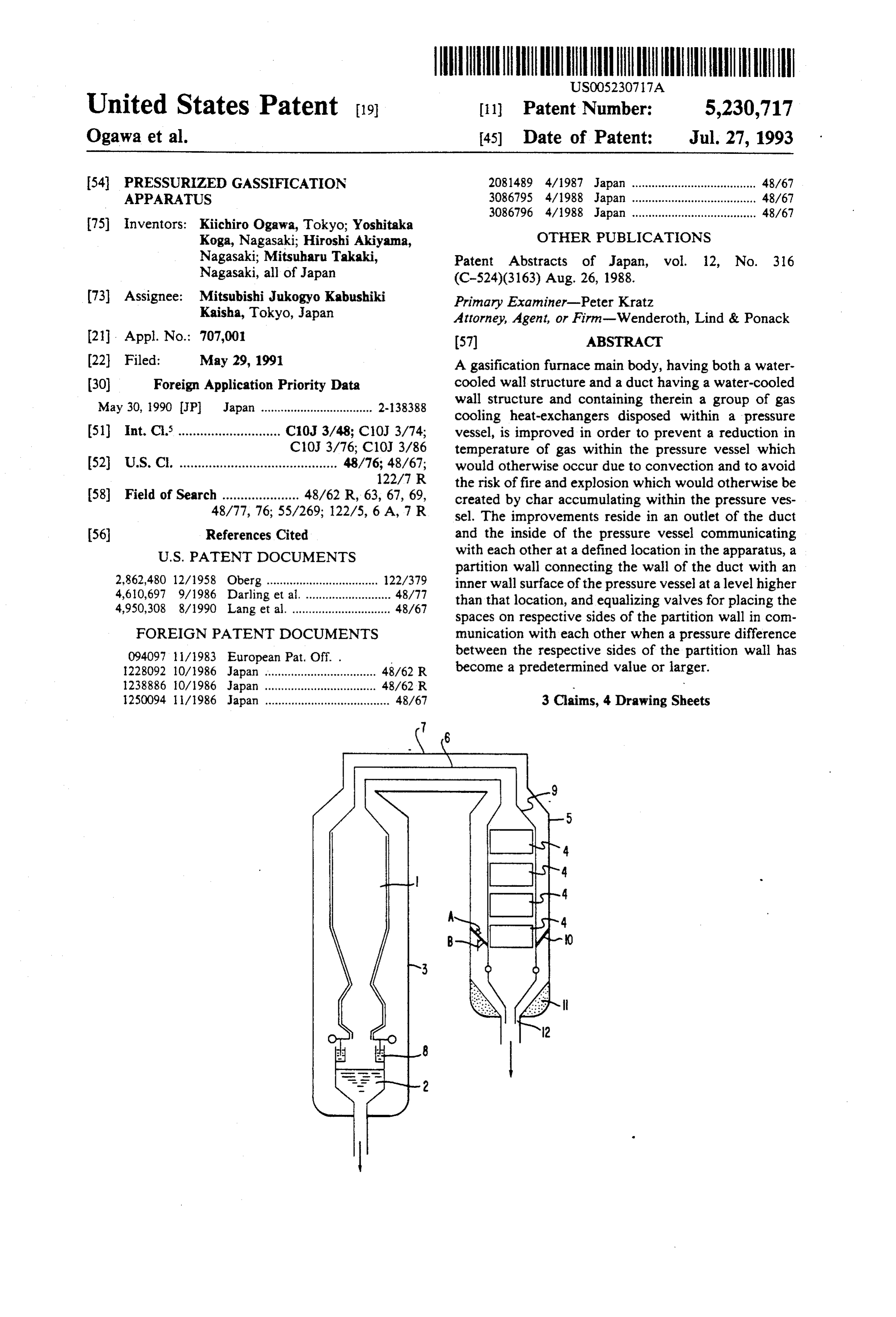
United States Patent (19) 11) Patent Number: 5,230,717 Ogawa et al. 45) Date of Patent: Jul. 27, 1993 54 PRESSURIZED GASSIFICATION 2081489 4/1987 Japan ...................................... 48/67 APPARATUS 3086795 4/1988 Japan ...................................... 48/67 3086796 4/1988 Japan ...................................... 48/67 75) inventors: Kiichiro Ogawa, Tokyo; Yoshitaka
Koga, Nagasaki; Hiroshi Akiyama, OTHER PUBLICATIONS
Nagasaki; Mitsuharu Takaki, Patent Abstracts of Japan, vol. 12, No. 316 Nagasaki, all of Japan (C-524)(3163) Aug. 26, 1988.
(73) Assignee: Mitsubishi Jukogyo Kabushiki Primary Examiner-Peter Kratz Kaisha, Tokyo, Japan Attorney, Agent, or Firn-Wenderoth, Lind & Ponack 21. Appl. No.: 707,001 (57) ABSTRACT (22 Filed: May 29, 1991 A gasification furnace main body, having both a water 30 Foreign Application Priority Data cooled wall structure and a duct having a water-cooled May 30, 1990 JP Japan .................................. 2-138388 wall structure and containing therein a group of gas cooling heat-exchangers disposed within a pressure 51 int. Cl. ............................ C10J 3/48; C10J 3/74; vessel, is improved in order to prevent a reduction in C107 3/76, C10J 3/86 temperature of gas within the pressure vessel which 52 U.S. C. ........................................... 48/76; 48/67; would otherwise occur due to convection and to avoid 122/7 R the risk of fire and explosion which would otherwise be 58 Field of Search ..................... 48/62 R, 63, 67, 69, created by char accumulating within the pressure ves 48/77, 76; 55/269; 122/5, 6A, 7 R sel. The improvements reside in an outlet of the duct 56 References Cited and the inside of the pressure vessel communicating
partition wall connecting the wall of the duct with an 2,862,480 12/1958 Oberg.................................. 122/379 inner wall surface of the pressure vessel at a level higher 4,610,697 9/1986 Darling et al........................... 48/77 than that location, and equalizing valves for placing the 4,950,308 8/1990 Lang et al. .............................. 48/67 spaces on respective sides of the partition wall in com FOREIGN PATENT DOCUMENTS munication with each other when a pressure difference 094097 11/1983 European Pat. Off. . between the respective sides of the partition wall has 1228,092 10/1986 Japan .................................. 48/62 R become a predetermined value or larger. 238886 0/1986 Japan .................................. 48/62 R.
250094 l/1986 Japan ...................................... 48/67 3 Claims, 4 Drawing Sheets
Page 2
Drawing sheet — no readable text.
Page 3
Drawing sheet — no readable text.
Page 4
Drawing sheet — no readable text.
Page 5
Drawing sheet — no readable text.
Page 6
quently, there is a shortcoming in that a complicated
PRESSURIZED GASSIFICATION APPARATUS device or equipment is necessary for adjusting and con trolling the feeding pressure of the inert gas by detect
BACKGROUND OF THE INVENTION ing the pressure within the furnace by means of a differ 1. Field of the Invention ential pressure gauge 041.
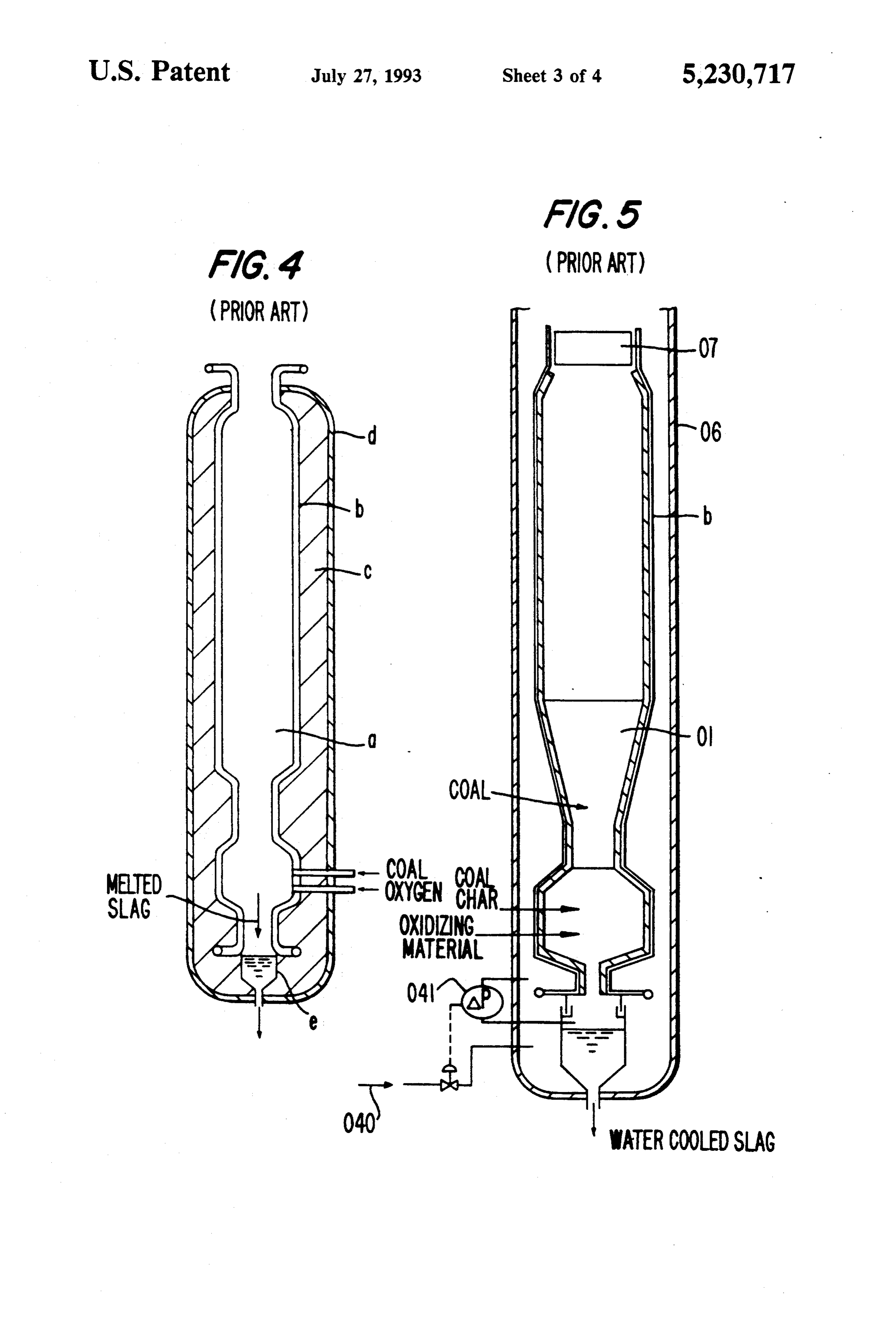
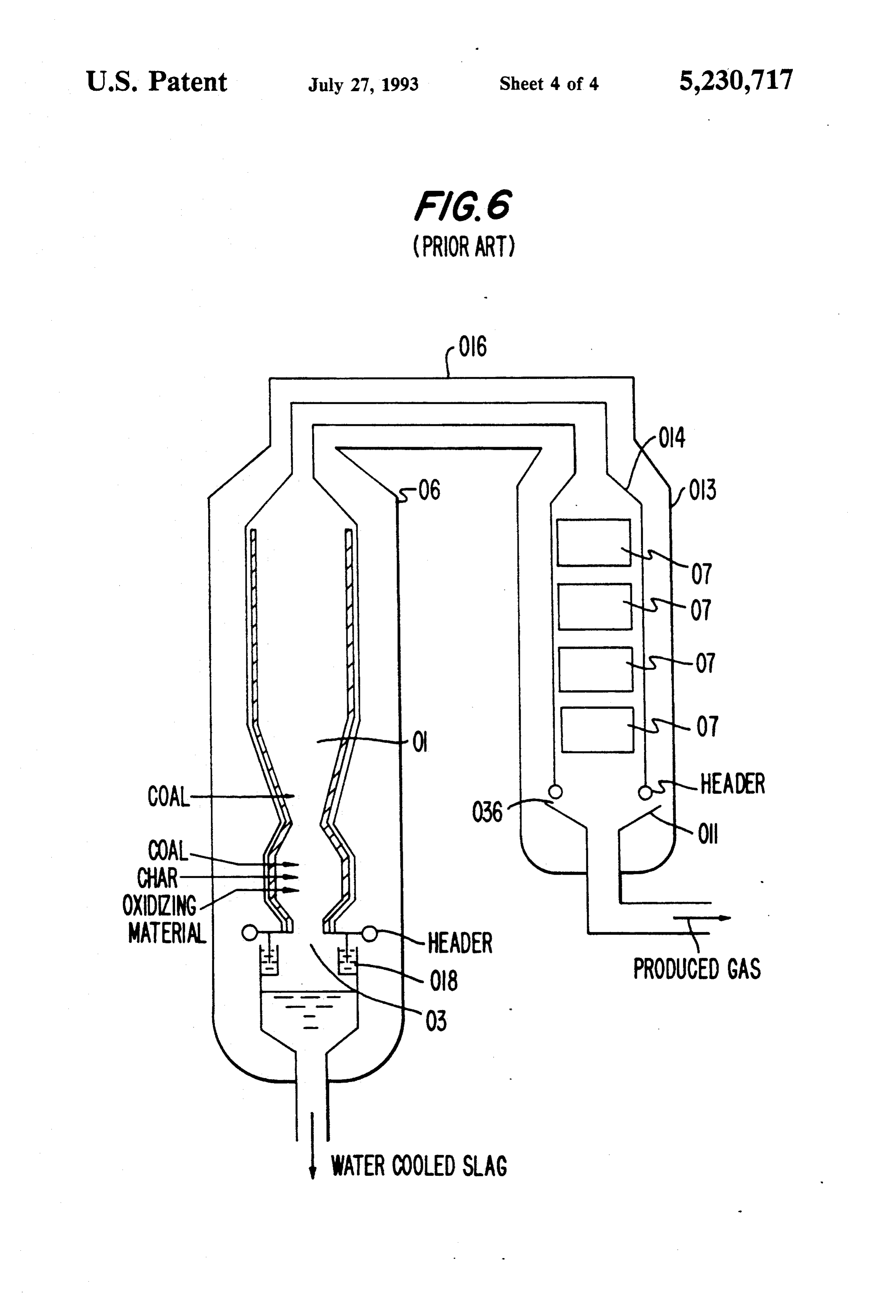
The present invention relates to improvements in a In order to eliminate these shortcomings, a pressur pressurized type gasification apparatus which includes a ized type gasification apparatus illustrated in FIG. 6 gasification furnace main body having a water-cooled was proposed (Japanese Patent Application No. wall structure and a duct having a water-cooled wall 60-221324 (1985), Laid-Open Japanese Patent Specifica structure and containing therein a group of gas cooling 10 tion NO. 62-81489 (1987)). In this apparatus, an interior heat-exchangers for recovering heat from gas produced of a pressure vessel 06 accommodating a gasification in the gasification furnace main body. furnace main body 01 and an interior of a pressure ves 2. Description of the Prior Art sel 013 accommodating a water-cooled wall 014 sur Every one of FIGS. 4 to 6 illustrates a different exam rounding a heat-exchanger group 07 communicating ple of a pressurized type coal gasification apparatus in 15 with the interior of the gasification furnace main body the prior art. 01 communicate with each other through a balance pipe At first, FIG. 4 shows one example of such apparatus 016. And, at a slag ejection port 03 of the gasification having a single-wall structure, in which reference char furnace main body 01 is provided a gas sealing device acter a designates a gasification furnace main body, 018 providing a water seal. In addition, at an outlet of characterb designates a water-cooled wall, character c 20 the water-cooled wall 014 is provided a gas receiver 011 designates a heat insulating material, character d desig nates a pressure vessel, and character e designates an mounted to the pressure vessel 013, and between the water-cooled wall 014 and the pressure vessel 013, and ash hopper. In a pressurized type gasification apparatus, between the water-cooled since the interior of the gasification furnace main body vessel 013 is formed a gaswall 014 and the pressure passageway 036 through is at high-temperature and high-pressure, in the case of 25 which a produced gas at a low temperature can freely a furnace wall having a single-wall structure such as the flow in and flow out.
illustrated example, in view of a structural strength it was necessary to form the furnace wall as an extremely theInpressure the apparatus shown in FIG. 6, the pressure within vessel 013 can be controlled in a self thick wall structure. However, not only is a thick fur balancing manner by allowing a low-temperature pro nace wall costly to manufacture but there is also a short duced gas at the outlet
of the water-cooled wall 014 coming in that the furnace is quickly damaged because surrounding the heat-exchanger group 07 to freely flow a thermal radiation effect cannot be obtained. Thus, this water-cooled structure does not adapt well to the high into the pressure vessel 013, and hence a constant pres temperature and high-pressure conditions of the interior sure difference can be maintained conforming to the of the furnace and is not economical if a sufficient wall 35 pressure variations within the gasification furnace main strength is to be provided. body 01. Consequently, pressure control can be Hence, as shown in FIG. 5, a pressurized type gasifi achieved very economically and reliably without neces cation apparatus having a so-called double-wall struc sitating special pressure detector means or control ture, in which a gasification furnace main body is dis means. In addition, by providing the outlet of the water posed within a pressure vessel, was proposed (Japanese cooled wall 014 as a free end, a difference in thermal Patent Application No. 60-48202 (1985), Laid-Open expansion between the water-cooled wall 014 and the Japanese patent Specification No. 61-207492 (1986)). pressure vessel 013 can be accommodated for. Further This double-wall structure is constructed of a gasifica more, since the sealing device 018 employing a water tion furnace main body 01 and a pressure vessel 06 seal is provided at the slag ejection port 03 of the gasifi containing the former therein. The inner pressure of the 45 cation furnace main body 01, a difference in thermal pressure vessel 06 is maintained at a pressure equal to or expansion between the gasification furnace main body a little lower than the inner pressure of the gasification 01 and the pressure vessel 06 also can be accommodated furnace main body 01. A pressure difference arises due for.
to the high pressure within the gasification furnace main However, the pressurized type gasification apparatus body 01 being present in a stepped portion of the gasifi shown in FIG. 6 and described is not considered to be cation furnace main body 01. In this case, the wall of the favorable in view of performance for the following gasification furnace main body 01 can be thin. Also, a reasons, and especially for reasons of safety, because a high thermal radiation effect can be produced by em low-temperature gas at the outlet of the water-cooled ploying, for example, a water-cooled wall structure. wall can freely flow into and flow out from the pressure Therefore, there is an advantage in that the gasification 55 vessel 013 without being subjected to any restriction. furnace main body has a long life. That is, the gas flowing into the pressure vessel 013 However, in the case of employing such a double fills the interior of the same vessel. And the gas coming wall structure, the pressure within the pressure vessel into contact with the water-cooled wall 014 is partly 06 must be maintained at a certain fixed pressure in heated by heat dissipating from the inside of the water correspondence with the pressure within the gasifica cooled wall resulting in a reduction of its specific grav tion furnace main body 01. Therefore, in the example ity, whereby it rises along the water-cooled wall 014. A shown in FIG. 5, a pressurized inert gas 040 is injected gas filling the upper portion is displaced downward due to the interior of the pressure vessel 06 (the exterior of to a difference in the specific gravity of the gases. In the gasification furnace main body 01). In this case, the other words, natural convection would occur within pressure of the inert gas fed into the pressure vessel 06 65 the pressure vessel 013. Since this low-temperature gas must be varied in correspondence with the pressure having fallen due to natural convection passes through change within the gasification furnace main body 01 the gas passageway 036, mixes into a principal flow and produced upon operation of the apparatus. Conse lowers the temperature of the produced gas, the condi
Page 7
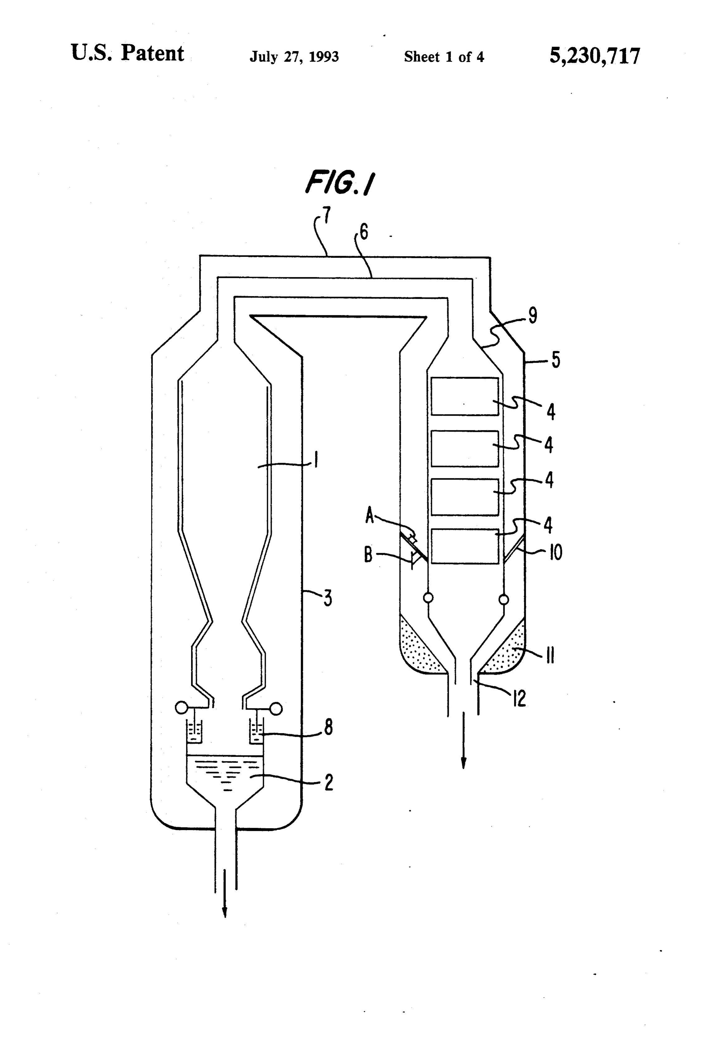
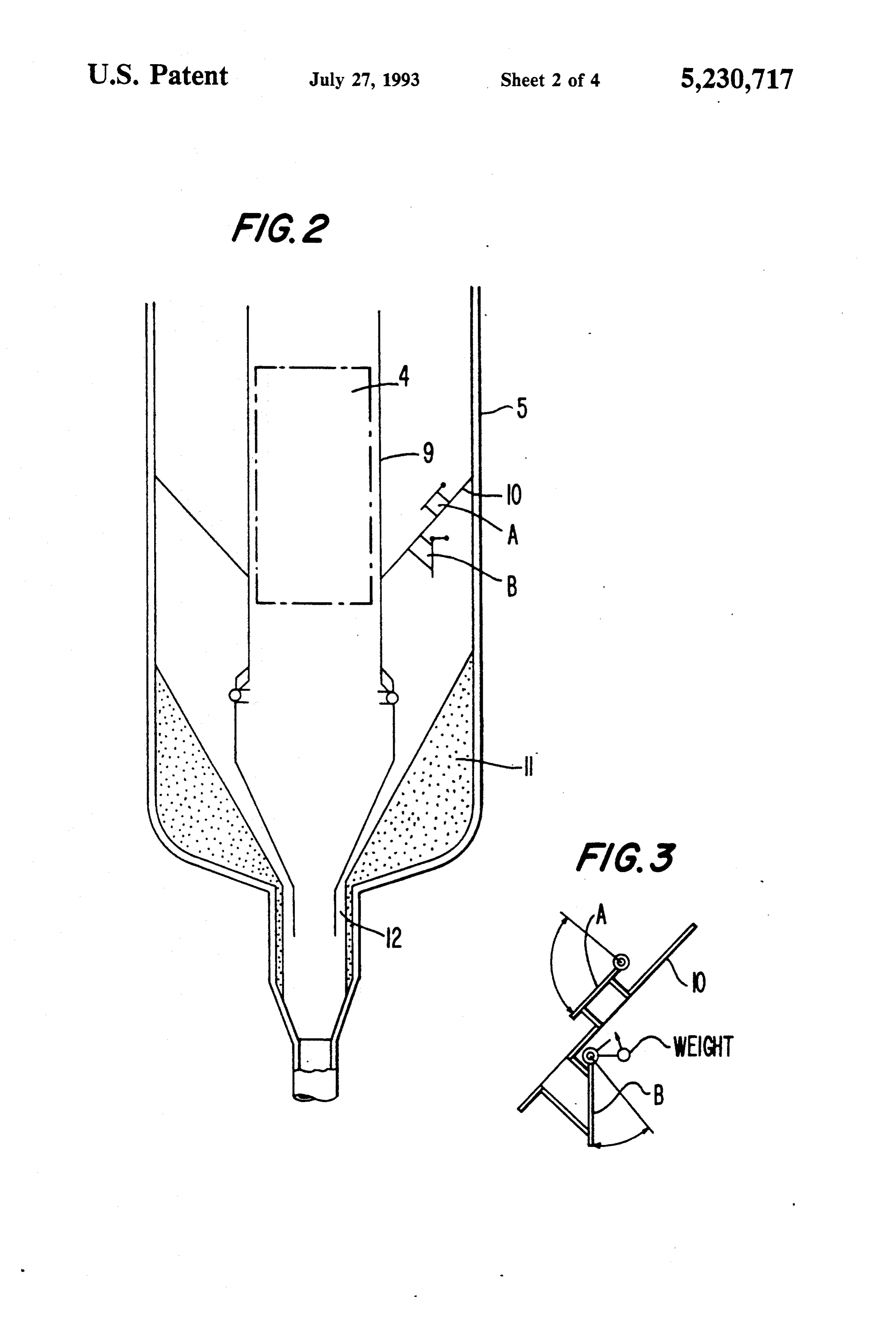
tion of the gas fed to an apparatus in the succeeding FIG. 2 is an enlarged schematic view of a bottom stage becomes unstable. As this is caused by a natural portion of a gas cooling heat-exchanger group in the convection phenomenon, it is difficult to preliminarily same apparatus;
estimate the amount of temperature change, and it is FIG. 3 is a detailed schematic view of equalizing impossible to control it. valves in the same bottom portion; and In addition, when the produced gas at the outlet of FIGS. 4 to 6 are schematic views of respective pres the water-cooled wall 014 flows into the pressure vessel surized type coal gasification apparatus in the prior art. 013 as described above, an unburnt carbon content DETAILED DESCRIPTION OF THE (char) contained in the produced gas also enters the 10 PREFERRED EMBODIMENTS pressure vessel. Char accumulating within the pressure vessel is undesirable in view of maintenance and man Now, the present invention will be described in agement of the apparatus and from the viewpoint of greater detail with reference to FIGS. 1 to 3 which safety because the accumulated material may ignite and illustrate one preferred embodiment of the invention. At first, referring to FIG. 1, a gasification furnace may cause fire due to various circumstances and it may 5 main even create a disaster such as an explosion or the like. havingbody 1 is formed of a water-cooled wall structure its inner surface covered by refractory material,
SUMMARY OF THE INVENTION and it is disposed within a pressure vessel 3 along with
It is therefore one object of the present invention to coolingslag hopper 2. On the other hand, a plurality of gas provide a pressurized type gasification apparatus hav 20 having aheat-exchangers 4 are contained within a duct 9 ing a double-wall structure in which a reduction in duct 9 is disposed within astructure, water-cooled wall and further, the temperature of a produced gas caused by natural con pressure vessels 3 and 5 are connectedvesselpressure
5. These pressure vection within a pressure vessel is prevented and a risk vessel connecting pipe 7 containing a gas communica offire and explosion caused by the accumulation of char tion pipe 6therein so as to form a structure for maintain within a pressure vessel is eliminated. 25 ing a pressure balance between the respective pressure According to one feature of the present invention, vessels. The gas communication pipe 6 places the inte there is provided an improved pressurized type gasifica rior of the gasification furnace main body1 in communi tion apparatus in which a gasification furnace main cation with the interior of the water-cooled wall duct 9. body having a water-cooled wall structure and a duct The slag ejection hopper 2 is connected with the having a water-cooled structure and containing therein 30 gasification furnace main body I via a water seal mecha a group of gas cooling heat-exchangers for recovering nism 8 so that a difference in thermal expansion caused heat from gas produced in the gasification furnace main by a temperature difference between the gasification body are disposed within a pressure vessel, wherein the furnace main body 1 and the pressure vessel 3 can be improvements reside in an outlet of the duct and the accommodated for perfectly.
inside of the pressure vessel communicating with each 35 On the other hand, an outlet portion of the water other, a partition wall connecting the wall of the duct cooled water duct 9 containing the group of gas cooling with an inner wall surface of the pressure vessel at a heat-exchangers 4 therein is not directly connected with level higher than the location where the outlet of the the pressure vessel 5 but communicates with the pres duct communicates with the interior of the pressure sure vessel 5 via a gas passageway 12 so that a low-tem vessel, and in that there are provided equalizing valves perature gas at the outlet of the heat-exchanger group for placing the respective spaces on opposite sides of the can freely flow into and out of the pressure vessel 5. partition wall in communication with each other when Thanks to this gas passageway 12, a difference in ther a pressure difference between the respective sides of the mal expansion between the water-cooled wall duct 9 partition has become a predetermined value or larger. 45 and the pressure vessel 5 can be accommodated for, According to the present invention, because the par cooling whereby the apparatus is highly reliable in that the gas tition wall is provided at a level higher than the location heat-exchanger group will not be damaged. where the outlet of the duct communicates with the This gas passageway 12 is dimensioned so as to insure a interior of the pressure vessel, the above-mentioned necessary minimum clearance through which gas can flow at a problems caused by the natural convection within the 50 sure in thefor maintaining a balance between the pres water-cooled wall duct 9 and the pressure in pressure vessel are obviated.
In addition, when a difference between the pressure theInpressure vessel 5.
addition, as shown more clearly in FIG. 2, a parti within the gasification furnace main body and the wa ter-cooled wall accommodating the heat-exchanger tion wall 10 is provided so as to connect the water cooled duct 9 containing the heat exchanger group group and the pressure within a pressure vessel contain 55 therein with the inner wall surface of the pressure vessel ing therein the water-cooled wall has reached a certain 5 at a level value or larger, the equalizing valves are opened, passageway higher than the above-mentioned gas flow 12. Furthermore, this partition wall 10 is whereby safety is insured. provided with equalizing valves A and B which open BRIEF DESCRIPTION OF THE DRAWINGS only in the case where a pressure difference between the respective sides of the partition wall has become a
The above-mentioned and other objects, features and predetermined value or larger.
advantages of the present invention will become more apparent by referring to the following description of theFIG.3 shows one example of the detailed structure of equalizing valves A and B mounted to the partition one preferred embodiment of the invention taken in wall 10. The equalizing valve A is constructed in such a conjunction with the accompanying drawings. 65 manner that it will automatically open upwards against In the accompanying drawings: gravity in the case where the pressure under the parti FIG. 1 is a schematic view of one preferred embodi tion wall 10 is higher than the pressure above the parti ment of the present invention; tion wall 10. The equalizing valve B is constructed in
Page 8
such a manner that it will automatically open against As described above, in the illustrated embodiment, gravity acting upon a weight mounted to a valve body the partition wall 10 is provided with the equalizing in the case where the pressure above the partition wall valves A and B within the pressure vessel 5. 10 is higher than the pressure under the partition wall As will thus be apparent from the pressurized type 10. gasification apparatus according to the present inven It is to be noted that the bottom portion of the pres tion, problems such as a lowering in the temperature of sure vessel 5 under the partition wall 10 is formed as a produced gas which occurred in the prior art as the conical by means of refractory material 11 for the pur result of natural convection of the gas within the pres pose of preventing dust accompanying the outflow and sure vessel and of the risk of fire and explosion resulting inflow of gas from accumulating at the bottom portion O from an accumulation of char within the pressure vessel of the vessel 5 as much as possible. are resolved. The apparatus thus exhibits high degrees In such an apparatus, a high-temperature gas pro of safety and reliability.
duced within the gasification furnace main body 1 has While a principle of the present invention has been its sensible heat thermally recovered in the gas cooling described above in connection with one preferred em heat-exchanger group 4, and it is fed as a low-tempera 15 bodiment of the invention, it is a matter of course that ture gas to a subsequent installation (not shown). In many apparently widely different embodiments of the addition, slag falling in the slag hopper disposed under present invention can be made without departing from the gasification furnace main body 1 is subsequently the spirit of the invention.
cooled and crushed. We claim:
In this preferred embodiment of the present inven 20 1. A pressurized gasification apparatus comprising: a tion, even in the event that the gas occupying the space gasification furnace main body having a water-cooled between the pressure vessel 5 and the water-cooled wall wall structure, a duct having a water-cooled wall struc duct 9 is heated by heat dissipating from the water ture, a group of gas cooling heat-exchangers contained cooled wall duct 9 and a natural convection of the gas within said duct, a pressure vessel in which said gasifi occurs due to a change in the specific gravity of the gas 25 cation furnace main body, said duct, and said group of within the pressure vessel 5, gas at the gas passageway gas cooling heat-exchangers are contained, the interior 12 at the outlet portion of the heat-exchanger group is of said duct communicating with the interior of said not influenced because the partition wall 10 is provided. gasification main furnace body so that said group of Thus, the lowering of the temperature caused by the gas-cooling heat exchangers recover heat from gas pro low-temperature gas within the pressure vessel flowing duced in said gasification main body, said duct having into the principal flow of the produced gas can be pre an outlet communicating with the interior of said pres vented. sure vessel at a defined location in the apparatus, a Furthermore, the equalizing valves A and B provided partition wall connecting the wall of said duct with an on this partition wall 10 ensure safety. More particu inner wall surface of said pressure vessel so as to parti larly, as described above, the equalizing valves A. and B 35 tion the interior of the pressure vessel into spaces on are provided for the purpose of maintaining the pres opposite sides of said partition wall, respectively, said sure difference between the inside of the water-cooled partition wall being disposed at a level in the apparatus wall duct 9 and the inside of the pressure vessel 5 at a that is above the location where said outlet of the duct certain constant balanced pressure difference which communicates with the interior of said pressure vessel, insures safety of the apparatus. In the event that the and equalizing valves operative to place the spaces on pressure difference has exceeded this balanced pressure opposite sides of said partition wall in open communica difference and has become abnormal, either one of the tion with each other when a pressure difference on equalizing valves A and B would automatically open opposite sides of said partition wall has become a prede and the pressure difference would be returned to a nor termined value or larger.
mal value. 45 2. A pressurized gasification apparatus as claimed in The above-described equalizing valves A and B have claim 1, wherein at least one of said equalizing valves is their appropriate specifications determined after a toler operative to place the spaces on opposite sides of said able pressure difference has been calculated taking into partition wall in open communication with each other consideration the structural strength and operating con when pressure on one side of said partition wall has ditions of the pressurized type gasification apparatus. In become higher than pressure on the other side thereof addition, the equalizing valves have such a structure by a predetermined value or larger, and the remainder that a fine granular char component contained in the gas of said equalizing valves place the spaces on opposite filling the inside of the pressure vessel 5 may hardly sides of said partition wall in open communication with accumulate thereon. Furthermore, if the equalizing each other when the pressure on said other side of said valves A and B are designed so that they can automati 55 partition wall has become higher than the pressure on cally maintain the pressure within the pressure vessel at said one side thereof by a predetermined value or an appropriate value even upon the start-up and stop of larger.
the pressurized type gasification apparatus and upon 3. A pressurized gasification apparatus as claimed in variations in the load on the apparatus, safety and reli claim 1, wherein the outlet of said duct having a water ability of the apparatus can be further improved. Specif. cooled wall structure forms a free end of said duct that ically, the valves are designed so as to operate at a is spaced inwardly from the inner wall surface of said pressure difference of 50-600 mm water column taking pressure vessel at said location to thereby define a gas into account a pressure difference between the upper passageway between said outlet and the inner wall sur side and the lower side of the partition wall, an effective face through which gas passageway the interior of said aperture area and the weight of the equalizing valve, 65 duct communicates with the interior of said pressure and the compressive strength of the water-cooled wall vessel.
duct and the pressure vessel. s: k
Provenance
- Collection
- Cited prior art
- Original PDF
- patentimages.storage.googleapis.com →
- Filed
- 1991-05-29
- Pages
- 8
- Method
- pdftotext (the PDF's own text layer) + pdftoppm 300dpi page scans
- Source
- Google Patents bibliographic record
- Granted
- 1993-07-27
- Inventors
- Kiichiro Ogawa; Yoshitaka Koga; Hiroshi Akiyama; Mitsuharu Takaki; Mitsubishi Heavy Industries Ltd
- Transcribed from
- patentimages.storage.googleapis.com →