(1003)
VIC Coil Assembly
Also written Voltage Intensifier VIC-Coil Assembly · VIC Coil-Array
Where it is first named
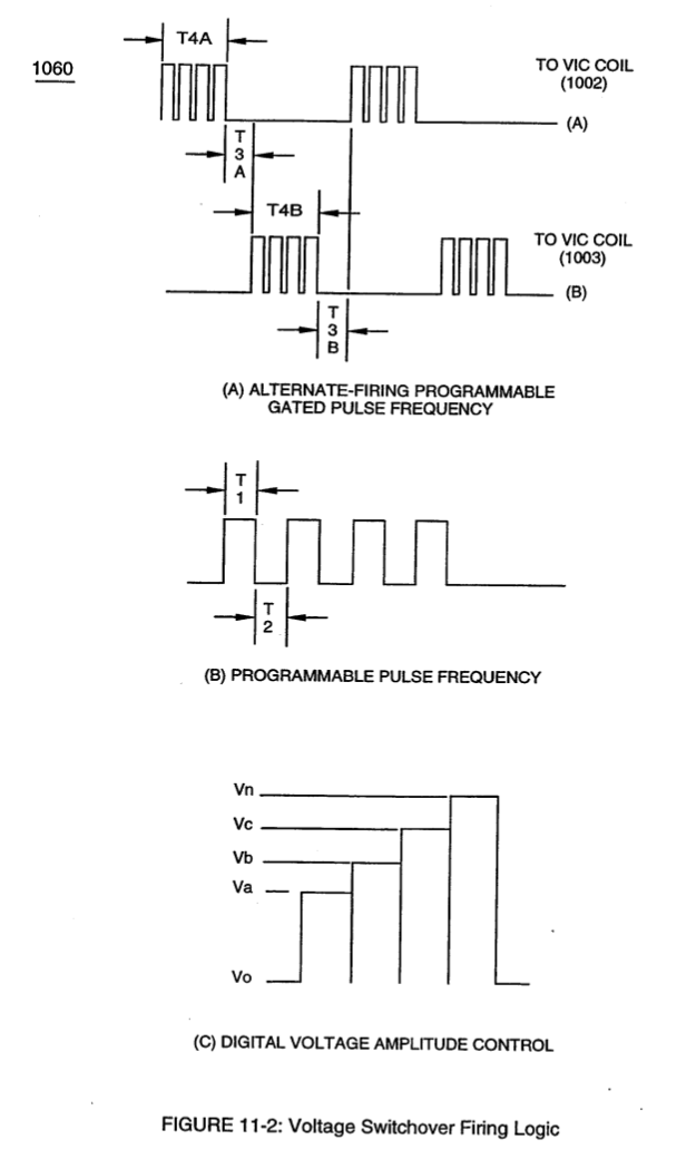
To reverse direction of the line of travel of the deflecting water molecule from left-hand movement to right-hand movement, another and completely separate Voltage Intensifier VIC-Coil Assembly (1003) of Figure (11-3) is periodically switched-on electrically by alternate voltage pulse waveform (T4B) once first voltage pulse wave-form (T4A) is terminated for a brief period of time (T3A)
How it is written
- (1003) 3×
- (1002/1003) 1× with (1002) VIC Coil-Array
Drawings 5
-
dual unipolar voltage pulse circuit (1010) of Figure (11-1) · Voltage Flexing Process
-
gated pulse-voltage waveform (1020) of Figure (11-2) · Voltage Flexing Process
-
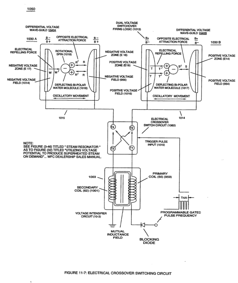
Differential Voltage Wave-Guild (1040B) · Electrical Crossover Switching Circuit
-
When (B+/B+ - B-/B- / 1030B) switch function is activated, switch terminals (T1/T2 - T3/T4) are closed. · Electrical Crossover Switching Circuit
-
(1030) of figure (11-3) · Voltage Flexing Process
Where it is named · 4
VIC Switchover Circuit 2×
-
Voltage Intensifier VIC-Coil Assembly (1003)
To reverse direction of the line of travel of the deflecting water molecule from left-hand movement to right-hand movement, another and completely separate Voltage Intensifier VIC-Coil Assembly (1003) of Figure (11-3) is periodically switched-on electrically by alternate voltage pulse waveform (T4B) once first voltage pulse wave-form (T4A) is terminated for a brief period of time (T3A)
-
VIC Coil-Array (1002/1003)
Electrically interfacing alternate "Switchover" voltage pulse wave-form (T4A/T4B) to each of both VIC Coil-Array (s) (1002/1003) of Figure (11-3) as schematically depicted, now, forms VIC Switchover Circuit (1010) of Figure (11-1).
Electrical Crossover Switching Circuit 2×
-
VIC Coil Assembly (1003)
To reduce the number of Voltage Intensifier VIC-Circuit to the use of only one VIC Coil Assembly (1003) while encouraging the utilization of using a Voltage Repelling Force (W - W') and/or (TT'), Electrical Crossover Circuit (1060) of Figure (11-7) is, now, electrically placed between VIC Coil Assembly (1003) and both Differential Voltage Wave-Guilds (1030A / 1030B), as so illustrated in (1050) of Figure (11-7).
-
VIC Coil Assembly (1003)
To reduce the number of Voltage Intensifier VIC-Circuit to the use of only one VIC Coil Assembly (1003) while encouraging the utilization of using a Voltage Repelling Force (W - W') and/or (TT'), Electrical Crossover Circuit (1060) of Figure (11-7) is, now, electrically placed between VIC Coil Assembly (1003) and both Differential Voltage Wave-Guilds (1030A / 1030B), as so illustrated in (1050) of Figure (11-7).