patent · US4145979
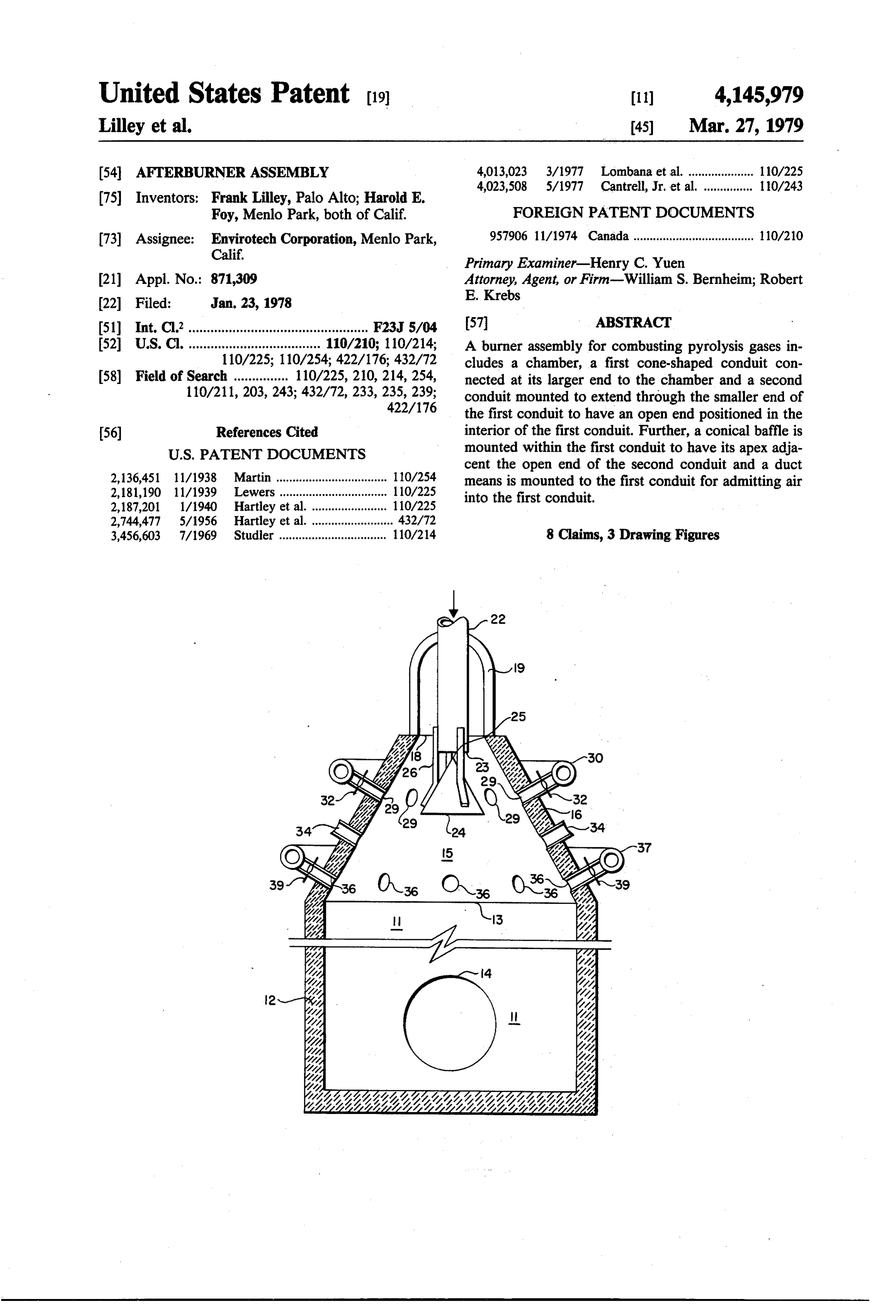
Afterburner assembly
27 March 1979
Page 1
United States Patent (19) 11) 4,145,979 Lilley et al. (45) Mar. 27, 1979 54 AFTERBURNER ASSEMBLY 4,013,023 3/1977 Lombana et al. .................... 110/225
(75) Inventors: Frank Lilley, Palo Alto; Harold E.
Foy, Menlo Park, both of Calif. FOREIGN PATENT DOCUMENTS (73) Assignee: Envirotech Corporation, Menlo Park, 957906 11/1974 Canada ..................................... 110/210 Calif. Primary Examiner-Henry C. Yuen 21 Appl. No.: 871,309 Attorney, Agent, or Firm-William S. Bernheim; Robert E. Krebs
(51) Int. C.’................................................. F23J 5/04 57 ABSTRACT 52 U.S. C. .................................... 110/210; 110/214; A burner assembly for combusting pyrolysis gases in 110/225; 110/254; 422/176; 432/72 cludes a chamber, a first cone-shaped conduit con 58) Field of Search ............... 110/225, 210, 214, 254, nected at its larger end to the chamber and a second 110/211, 203, 243; 432/72, 233, 235, 239; conduit mounted to extend through the smaller end of 422/176 the first conduit to have an open end positioned in the (56) References Cited interior of the first conduit. Further, a conical baffle is
cent the open end of the second conduit and a duct 2,136,451 11/1938 Martin ................................. 110/254 means is mounted to the first conduit for admitting air 2,181,190 1 1/1939 Lewers .............. -a - 110/225 into the first conduit.
2,187,201 1/1940 Hartley et al......... ... 110/225 2,744,477 5/1956 Hartley et al. ........ ... 432/72 3,456,603 7/1969 Studler ................................. 110/214 8 Claims, 3 Drawing Figures
Page 2
Drawing sheet — no readable text.
Page 3
Drawing sheet — no readable text.
Page 4
hollow cone to have a larger circular end 13 and a
AFTERBURNER ASSEMBLY spaced-apart smaller circular end 18. The larger circu BACKGROUND lar end 13 is connected in gas flow communication to 1. Field of the Invention the inlet end 13 of the chamber 11. Preferably the first 5 conduit 15 is located vertically above the chamber 11 so
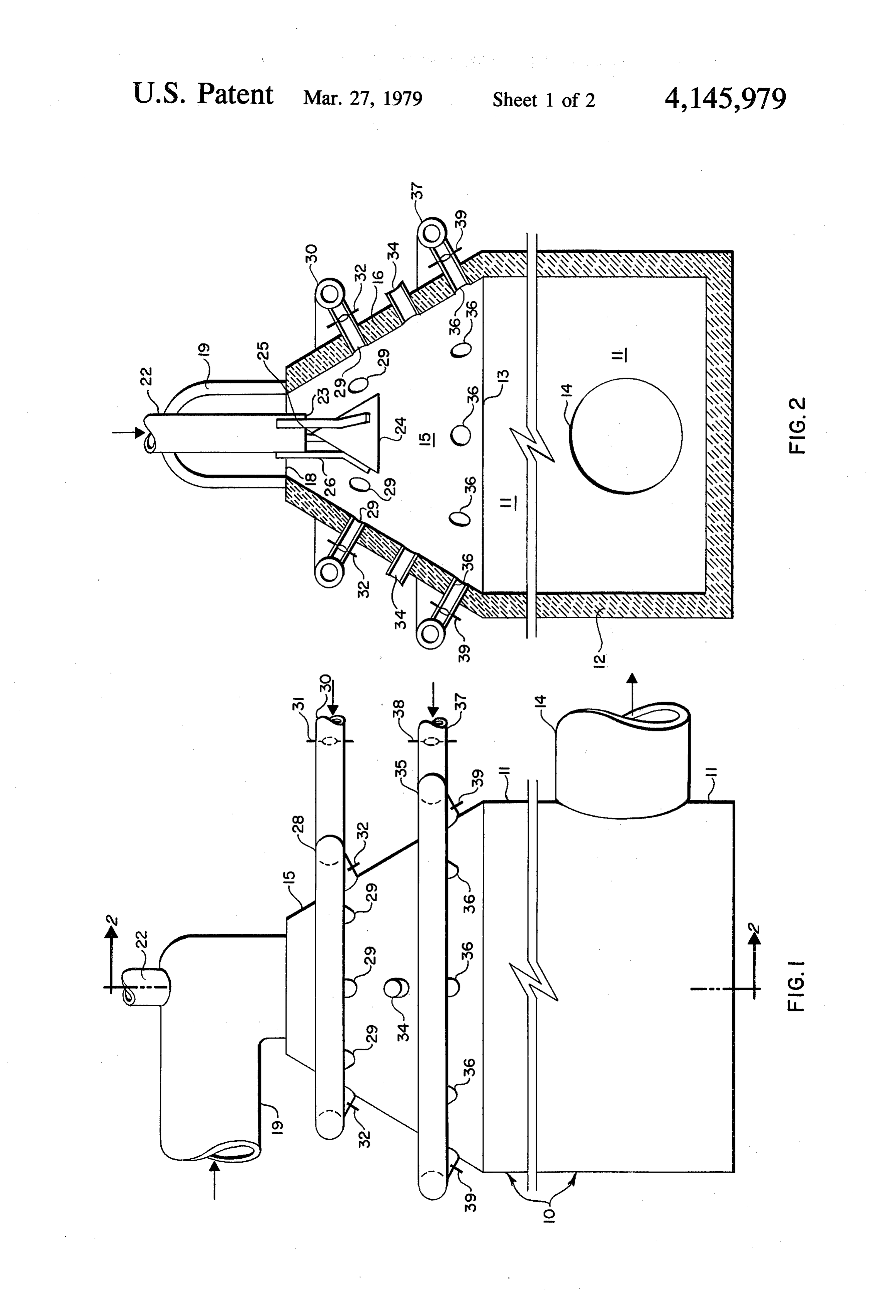
The invention relates in general to a burner for com that the openinlet end 13 is above the open outlet 14. A busting gaseous fuels. gas duct 19 is connected to the smaller circular end 18 2. State of the Art for admitting a gas stream to the chamber 11. It is known to produce charcoal by pyrolyzing wood A cylindrical second conduit 22 is connected in gas chips under a reducing atmosphere (oxygen deficient) 10 flow communication to the smaller end 18 of the first in a multiple hearth furnace. This pyrolysis produces conduit 15 and mounted to extend concentrically gases which are not completely combusted. To recap through the ture the heat content of these pyrolysis gases, the gases 23 positionedsmaller end 18 to have an open circular end in the interior of the first conduit 15 to have been passed to an afterburner to complete combus admit a first air stream to the chamber 11. Preferably, tion of the gases and from the afterburner passed to a 15 the second conduit 22 is slideably mounted so that the heat exchanger.
Heretofore, this approach to recapturing the heat position of the open circular end 23 within the first content of pyrolysis gases has not been entirely satisfac 22 extends along conduit 15 the axis on which the second conduit tory. Afterburners have commonly allowed uncom order to adjust thefirst into the conduit 15 can be changed in combustion characteristic of the busted gases to pass through to the heat exchanger. 20 burner assembly 10.
Such uncombusted gases cause damage to the heat ex Within the first conduit 15 a conical baffle 24 is changer by providing a reducing atmosphere which is mounted to have its apex 25 adjacent the open end 23 of conducive to corrosion in the heat exchanger and by the second conduit 22. The surface of the baffle 24 allowing combustion, which results in overheating, to diverges outward from the apex 25 equal distance from occur in the heat exchanger. 25 an axis which is an extension of the cylindrical axis of In addition, these afterburners have typically em the second conduit 22. Bars 26 mount the conical baffle ployed small diameter orifices and passages to convey the pyrolysis gases to achieve good mixing of the pyrol 24The to the second conduit 22 at the open end 23. ysis gases with oxygen which is needed to combust the mountedfirstadjacentconduit 15 is encircled by a bustle main 28 the smaller end 18. A plurality of gases. These small orifices and passages are undesirable 30 nozzles 29 are spaced along the bustle main 28 to inter because of possible clogging by particulates carried in connect in gas flow communication the bustle main 28 the gases. and the interior of the first conduit 15. Through these OBJECTS OF THE INVENTION nozzles 29 a second air stream is admitted into the first conduit 15 to mix with the gas stream admitted through
An object of this invention is to provide a burner with 35 duct 19 and the first air stream admitted through second which to complete combustion of pyrolysis gases pro conduit 22. The nozzles 29 extend through the sidewall duced in a multiple hearth furnace. Another object is to of the first conduit 15 at an angle to the sidewall which provide a burner achieving good mixing of pyrolysis is approximately perpendicular. The second air stream gases with oxygen without conveying the pyrolysis enters gases through small orifices or passages. 40 nected the bustle main 28 through an air duct 30 con to the bustle main 28. The flow of the second air
BRIEF DESCRIPTION OF THE DRAWINGS stream is controlled by butterfly dampers 31 and 32, Further objects and advantages of the invention may mounted in the air duct 30 and nozzles 29 respectively. Apertures 34 through the wall of first conduit 45 be readily ascertained by reference to the following description and appended drawings, which are offered 45 provide tures 34 means for mounting pilot burners. The aper are formed in the first conduit 15 between the by way of description only and not in limitation of the bustle main 28 and the open end 13 of the chamber 11. invention, the scope of which is defined in the appended A second bustle main 35 is mounted to encircle the claims. first conduit 15 adjacent the larger end 13. A plurality In the drawings: of nozzles 36 are spaced along the bustle main 35 to FIG. 1 is a side view of a burner according to the 50 interconnectingas flow communication the bustle main present invention.
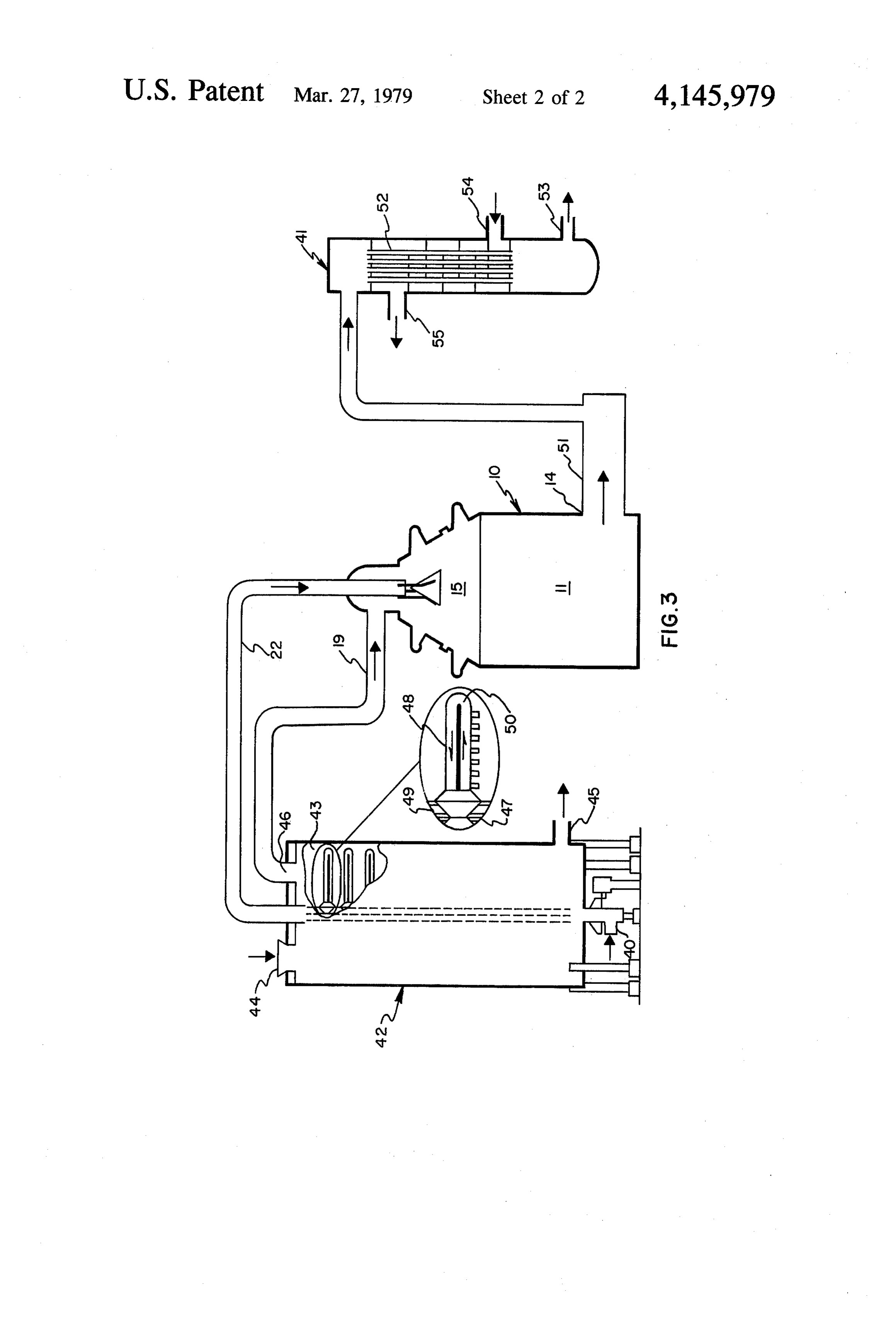
FIG. 2 is a sectional view of the burner of FIG. 1 35 and the interior of the first conduit 15. The cooling air stream enters the bustle main 35 through an air duct taken along the line 2-2 for viewing in the direction of 37 connected to the bustle main 28. To control the flow the arrows. of the cooling air stream, butterfly dampers 38 and 39 FIG. 3 is a pictorial schematic of a pyrolysis gas 55 are mounted in the air duct 37 and nozzles 36, respec system employing the burner of FIG. 1. tively.
PREFERRED EMBODIMENT OF THE FIG. 3 is a pictorial schematic of a heat recovery INVENTION system which includes the burner assembly 10, a heat exchanger 41 and a multiple hearth furnance 42. The
As shown in FIGS. 1 and 2, a burner assembly 10 for 60 multiple hearth furnace 42 includes a furnace chamber combusting gaseous fuels includes a chamber 11 lined 43 having an inlet 44 for admitting feed, a first outlet 45 with refractory 12 and having an open inlet end 13 and for discharging solids, and a second outlet 46 for dis an outlet 14. The outlet 14 can be located at the opposite charging gases. The second outlet 46 is connected in end of the chamber 11 from the open inlet end 13, but, flow communicaton to duct 19.
is preferably mounted at an angle of about ninety de- 65 Mounted in the furnace chamber 43 is a central shaft grees with respect to open inlet end 13. 47 supporting a plurality of rotatable arms 48. A cooling The assembly 10 also incorporates a first conduit 15, system for circulating air for cooling the shaft 47 and lined with refractory 16 and shaped like a truncated the arms 48 includes a conduit 49 extending in the shaft
Page 5
47 and passages 50 in the arms connected to the conduit interior of said first conduit to admit a first air 49. Air for cooling is admitted to conduit 49 through an stream to said chamber;
inlet 40 located at the bottom of the furnace 42. Follow d. a conical baffle mounted within said first conduit ing circulation the air is discharged from the conduit 49 and having its apex adjacent said open end of said to the second conduit 22 of the assembly 10. 5 second conduit so that the first air stream upon The outlet 14, of the assembly 10 is connected in flow exiting said open end of said second conduit di communication by a duct 51 to the heat exchanger 41. verges over said baffle with a conical flow pattern; The heat exchanger 41 can be any of many known di and rect and indirect, co-current and counter-current type e. duct means mounted to admit a second air stream heat exchangers. The heat exchanger 41 shown in FIG. 10 into said first conduit and positioned so that the 3 is of a indirect counter-current type. The hot gases second air stream upon admission, converges with the first air stream.
from the assembly 10 enter tubes 52 of the heat ex 2. An assembly according to claim 1 wherein said first changer 41 from duct 51 and are discharged through conduit and second conduit are coaxially mounted at duct 53. A gas, such as air, to be heated enters the heat said smaller exchanger through duct 54 and is discharged through 15 stream entersend of said first conduit so that the gas said smaller end as an annulus of flow duct 55. about the exterior of said second conduit. In operation, a gas stream containing fuel, such as the 3. An assembly according to claim 1 wherein said gases from the multiple hearth furnace 42 being oper conical baffle is mounted to said second conduit. ated in a pyrolysis mode, is delivered to the chamber 11 4. An assembly according to claim 1 further including of assembly 10 through duct 19. Upon entering the a second duct means mounted in gas flow communica smaller end 18 of the first conduit 15, this gas stream is 20 tion with said chamber to admit additional air down in the form of an annulus surrounding the second con stream of said first duct means.
duit 22. A first air stream, such as the heated cooling 5. An assembly according to claim 1 wherein said shaft air from the multiple hearth furnace 42, containing outlet of said chamber is oriented at an angle of about oxygen to be mixed with the gas stream to allow com 25 ninety degrees with respect to said inlet of said cham bustion is delivered to the chamber 11 through the sec ber.
ond conduit 22 at the open end 23. Upon exiting 6. A heat recovery system for recovering the heat through the open end 23, this first air stream contacts content of pyrolysis gases generated in a multiple hearth the baffle 24 and assumes a diverging conical flow pat furnace, said system comprising:
tern over the baffle 24 similar to the conical shape of a. an afterburner including:
first conduit 15. This diverging pattern produces a con 30 i. a chamber having an open inlet end and an open fluence of the first air stream with the gas stream. A outlet;
second air stream containing additional oxygen to be ii. a first conduit shaped like a truncated hollow mixed with the gas stream is admitted to the chamber 11 cone and connected in gas flow communication, through nozzles 29 with a converging conical flow at its larger end, to said inlet end of said chamber pattern. This latter flow pattern produces a confluence 35 for admitting a gas stream to said chamber; of the second air stream with gas stream and first air iii. a cylindrical second conduit connected in gas stream adjacent the downstream end of the baffle 24 to flow communication with said first conduit and provide a combustible mixture of gases. Self-sustaining mounted to extend through the smaller end of combustion can be established. Pilot burners mounted in said first conduit to have an open end positioned aperatures 34 provide initial heat and ignition for com in the interior of said first conduit to admit a first bustion. After combustion the gases are discharged air stream to said chamber; through outlet 14 and delivered to the heat exchanger iv. a conical baffle mounted within said first con 41. duit and having its apex adjacent said open end of said second conduit so that the first air stream
If needed, cooling can be provided in the assembly 10 upon exiting said open end of said second con by introducing air through nozzles 36 to prevent tem-4s duit diverges over said baffle with a conical flow peratures above those the assembly 10 can withstand. pattern; and V The burner assembly 10 has several desirable charac . . duct means mounted to admit a second air teristics. The assembly 10, without the utilization of stream into said first conduit and positioned so small orifices or small passages, achieves good mixing that the second air stream, upon admission, con of gases. Further, the assembly 10 minimizes the possi 50 verges with the first air stream; and bility of additional combustion occurring downstream b. a multiple hearth furnace including a chamber of the assembly 10. Even further, the orientation of the having a feed inlet, a solids outlet and a gas outlet; outlet 14 at an angle to the inlet 13 facilitates departure a central shaft mounted in said chamber, a plurality of heavy particles from the combusted gases to prevent of rotatable arms mounted within said chamber and their escape to the atmosphere downstream of the as 55 supported from said central shaft; and means for sembly 10. delivering the exhaust gases from said gas outlet of We claim: said furnace to said smaller end of said first conduit 1. An assembly for combusting pyrolysis gases which of said afterburner.
comprises: 7. A heat recovery system according to claim 6 fur a. a chamber having an open inlet end and an open ther including an air cooling system having means for outlet; circulating air in said central shaft and plurality of arms b. a first conduit shaped like a truncated hollow cone for cooling and including means for delivering the air and connected in gas flow communication, at its from said air cooling system after circulation to said larger end, to said inlet end of said chamber for second conduit of said afterburner.
admitting a gas stream to said chamber; 8. A heat recovery system according to claim 6 fur c. a cylindrical second conduit connected in gas flow 65 ther including a heat exchanger and means for deliver communication with said first conduit and ing gases from said open outlet of said afterburner to mounted to extend through the smaller end of said said heat exchanger.
first conduit to have an open end positioned in the + k is
Provenance
- Collection
- Cited prior art
- Original PDF
- patentimages.storage.googleapis.com →
- Filed
- 1978-01-23
- Pages
- 5
- Method
- pdftotext (the PDF's own text layer) + pdftoppm 300dpi page scans
- Source
- Google Patents bibliographic record
- Granted
- 1979-03-27
- Inventors
- Frank Lilley; Harold E. Foy; Envirotech Corp
- Transcribed from
- patentimages.storage.googleapis.com →