patent · US5310334A
Method and apparatus for thermal destruction of waste
10 May 1994
Page 1 — bibliographic record
United States Patent 19 11) Patent Number: 5.310,334
Spiros (45) Date of Patent: May 10, 1994 54 METHOD AND APPARATUS FOR 4,48,889 /1984 Sikander et al. ................ 10/21 X THERMAL DESTRUCTION OF WASTE 4,680,008 7/1987 Rioux .............................. 110/21 X
75 Inventor: Spiro Spiros, Mascot, Australia 5,169,605 12/1992 Carpentier .......................... O/214 (73) Assignee: Air Duke Australia, Ltd., Sydney, Primary Examiner-Larry Jones Australia Attorney, Agent, or Firm-James E. Brunton 21 Appl. No.: 892,754 (57) ABSTRACT (22 Filed: Jun. 3, 1992 An apparatus for removing contaminates from indus 51) Int. Cl. .............................................. F23D 14/00 trial waste streams by thermal destruction in which (52) U.S. C. ........................................ 431/5: 431/198; contaminated waste emission gases are controllably 431/264; 423/210; 110/215; 10/216; 110/344 intermixed with hydroxy gas and the mixture thus 58) Field of Search..................... 431/5, 12, 198,258, formed ignited within a combustion chamber of unique 431/264, 278, 285; 110/210, 211, 212, 214; design. The temperature within the combustion cham 432/72; 422/183, 168, 182; 423/210 ber is maintained at no less than 3000 degrees Fahren
heit to achieve molecular
disassociation
the pollut ants contained within the emission gas into harmless 4,145,979 3/1979 Lilley et al. ...................... 432/72 X 4,421,474 12/1983 Meyer ................................. 431/15 16 Claims, 3 Drawing Sheets
Page 2
Drawing sheet — no readable text.
Page 3
Drawing sheet — no readable text.
Page 4
Drawing sheet — no readable text.
Page 5
ature ideally suited for the safe and effective destruction
METHOD AND APPARATUS FOR THERMAL of hazardous waste.
DESTRUCTION OF WASTE The injector assembly of the apparatus is water cooled to maintain the temperature inside the assembly
BACKGROUND OF THE INVENTION 5 below about 300° C., thus keeping the flame outside the I. Field of the Invention nozzle and effectively preventing potential backflash. The present invention relates generally to a method The dimensions of the orifices provided in both the and apparatus for the thermal destruction of waste. injector element and the burner nozzle are designed to More particularly, the invention concerns a novel after optimum burning of the hydroxy gas within the com burner apparatus and its method of use for removing 10 bustion chamber of the apparatus. Additionally, the pollutants from industrial waste streams by high tem angle of the injection of the gas into the combustion perature thermal destruction using hydroxy gas. chamber is precisely controlled so as to focus the con 2. Discussion of the Invention centration of the heat energy towards the center of the Industries throughout the world have come under 15 burner. Further, the residence time of the contaminates increasing regulatory pressure to limit the quantities of within the burner is optimized to effectively complete pollutants discharged to the surrounding environments. their destruction resulting in relatively rapid kinetics. Of particular concern is the removal from industrial By changing direction of gas flow within the injector assembly waste streams of priority pollutants such as polyaro high velocity at least four times, the hydrogen burns at very matic hydrocarbons (PAH), pesticides, heavy metals, 20 and combustion can be easily and safely volatile organic compounds (VOC), and PCB, to name terminated. Also, due to the absence of air inside the but a few. The thrust of the present invention is to re burner a unidirectional flow is maintained at all times move these priority pollutants from gaseous emissions during the combustion process.
by high temperature thermal destruction using hydroxy With this summary description of the apparatus of the gas, that is, a gaseous mixture of hydrogen and oxygen. 25 invention in mind, it is an object of the present invention While the use of hydroxy gas to accomplish high to provide a method and apparatus for removing con temperature burning is not new, the use of this gas in a taminates from industrial waste streams by thermal closely controlled environment for the highly efficient destruction in which contaminated waste emission gases thermal destruction of priority pollutants presents excit are controllably intermixed with hydroxy gas and the ing, heretofore largely unexplored possibilities. mixture thus formed ignited in the absence of air within a combustion chamber of unique design.
SUMMARY OF THE INVENTION Another object of the invention is to provide an appa The apparatus of the present invention comprises a ratus of the aforementioned character in which the sealed combustion chamber having a unique configura gaseous mixture is controllably introduced into the tion into which a precisely controlled mixture of hy 35 combustion chamber in a manner to optimize the safe droxy gas and the gaseous waste emissions to be ther and complete destruction of the contaminates. mally destroyed can be introduced. The gaseous mix Another object of the invention is to provide an appa ture flows into the combustion chamber via an injector ratus as described in the preceding paragraph in which assembly of unique design which includes an injector the injector assembly used to inject the gases into the element and a burner nozzle. After introduction of the combustion chamber is water cooled to prevent unde gaseous mixture into the combustion chamber, it is con sirable backflash.
trollably ignited in the absence of airby a novel arc type Still another object of the invention is to provide an igniter assembly. apparatus in which the injector assembly is uniquely As discussed in detail in Australian Patent specifica designed path to cause the gaseous mixture to flow along a tion No. 7141 1/74 published Jan. 22, 1976, considerable 45 tortuous nation of thereby insuring safe and effective termi combustion at the end of the destruction cycle.
energy is associated with the dissociation of molecular Another object of the invention is to provide an appa oxygen into atomic oxygen by passing this gas through an arc. As observed in the Australian patent, this prop ratus of the class described which is highly effective in erty can be usefully employed to generate temperatures accomplishing ants such as virtually complete destruction of pollut polyaromatic hydrocarbons, heavy metals, even higher than those previously attainable with, for 50 example, an atomic hydrogen flame. The significance of volatile organics, pesticides and the like. the energy which can be obtained in this way can be apparatus Yet another object of the invention is to provide an appreciated from the following reactions that take contaminates for thermal destruction of industrial waste place, and the heat energies associated therewith, when 55 operation, is ofwhich simple is both efficient and reliable in design and can be economically hydrogen and oxygen are both passed through an elec constructed and operated.
tric arc. Thus:
BRIEF DESCRIPTION OF THE DRAWING
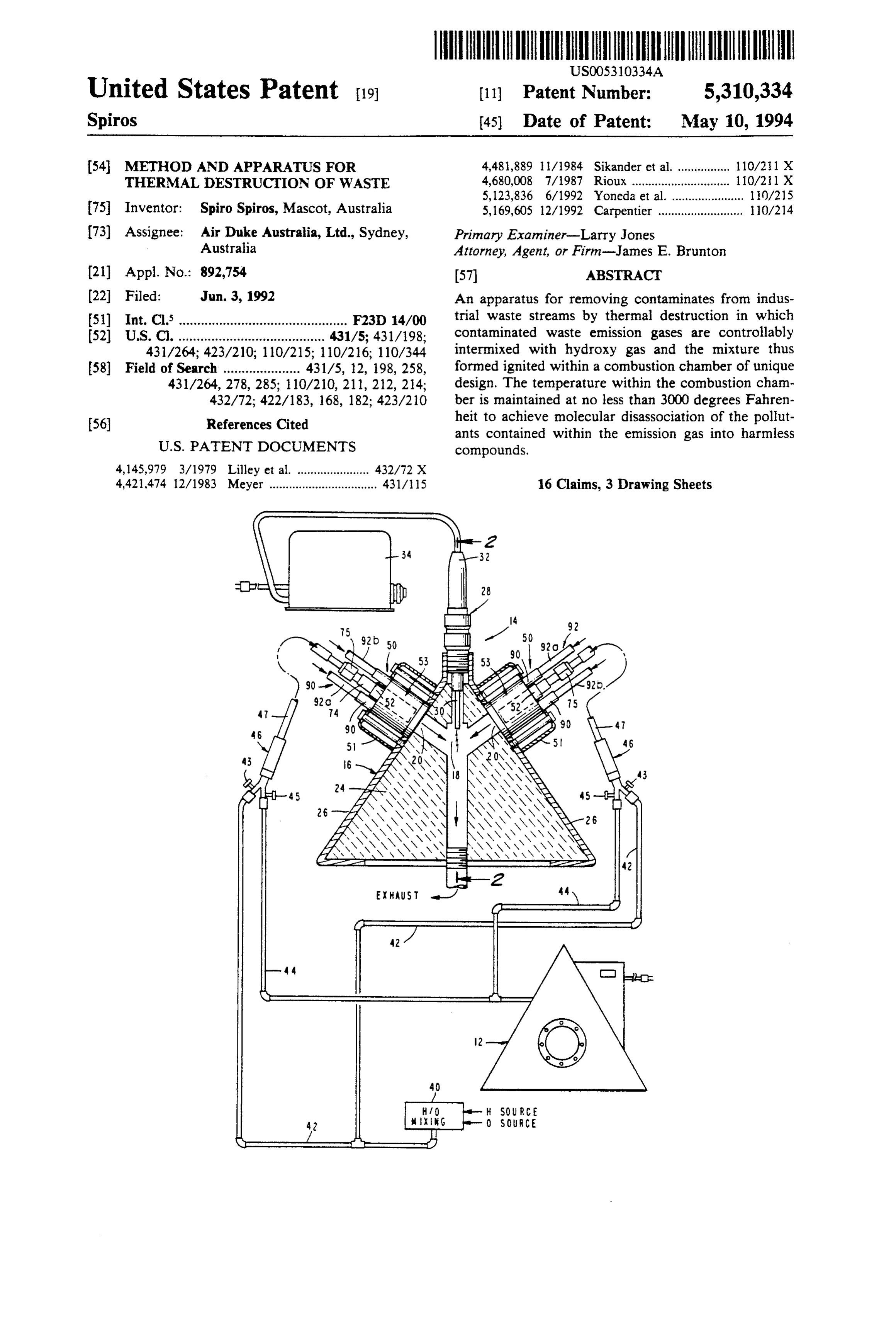
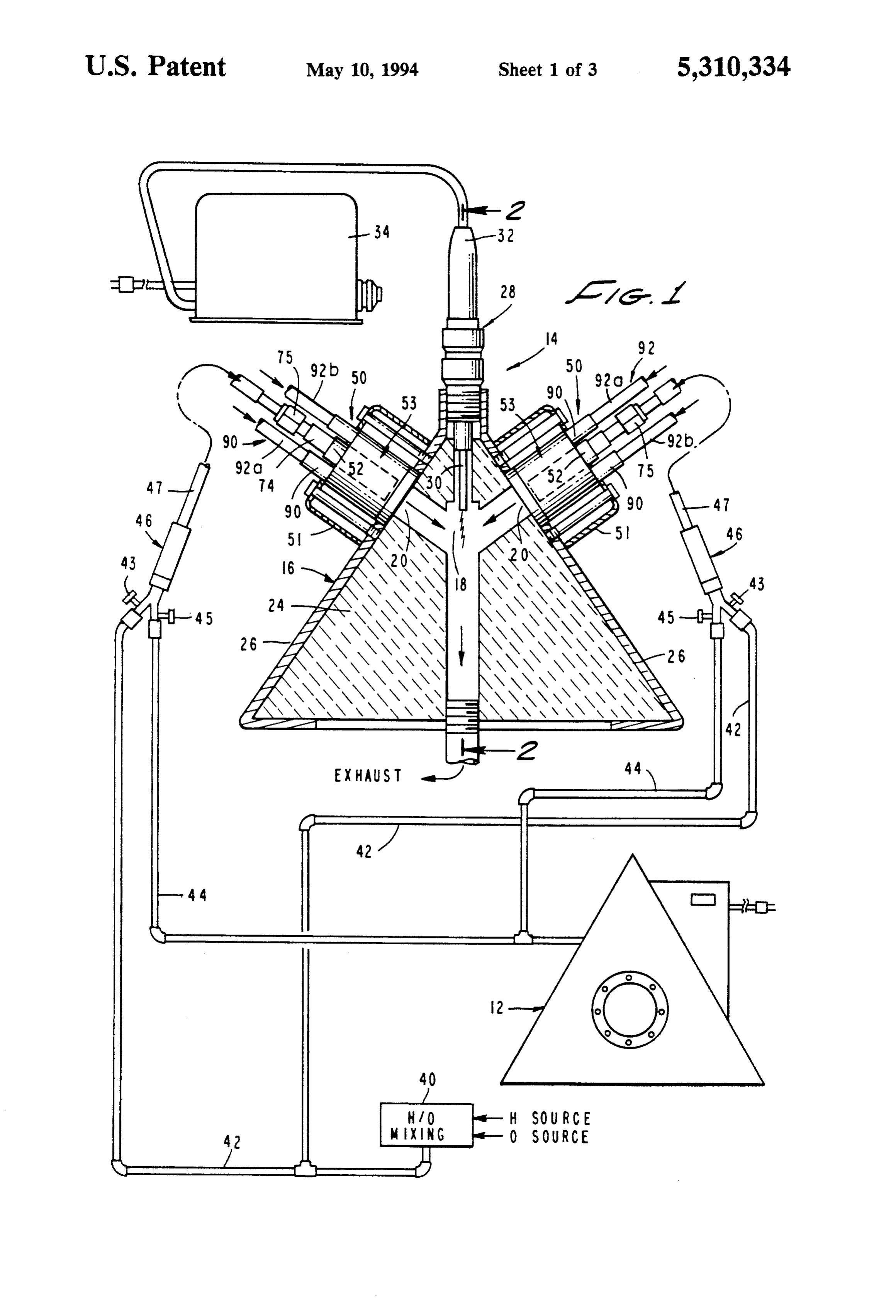
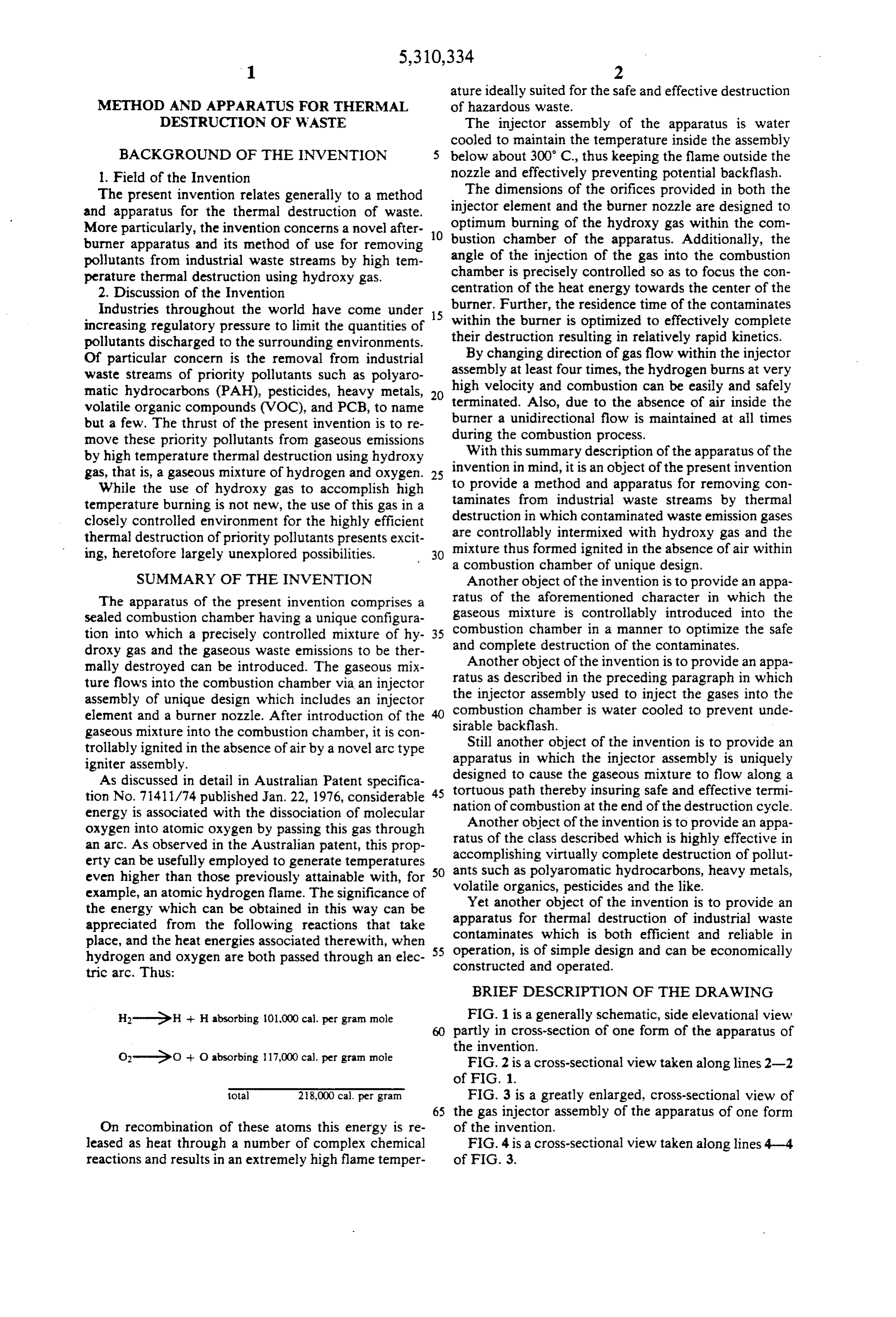
H-GeH -- Habsorbing 101,000 cal. per gram mole FIG. 1 is a generally schematic, side elevational view partly in cross-section of one form of the apparatus of the invention.
O-GO + O absorbing 117,000 cal. per gram mole FIG. 2 is a cross-sectional view taken along lines 2-2 of FIG. 1.
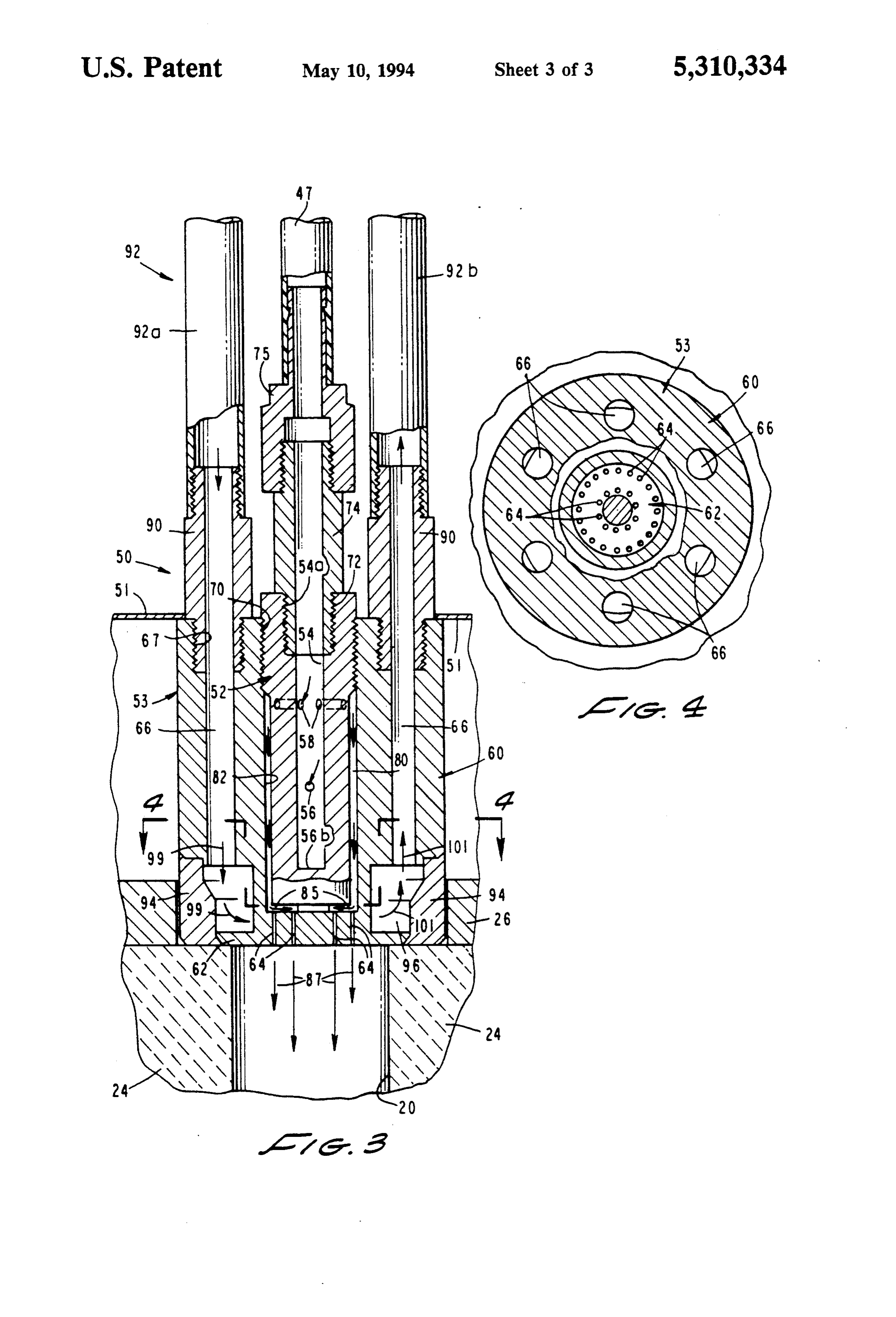
total 218,000 cal. per gram FIG. 3 is a greatly enlarged, cross-sectional view of 65 the gas injector assembly of the apparatus of one form
On recombination of these atoms this energy is re of the invention.
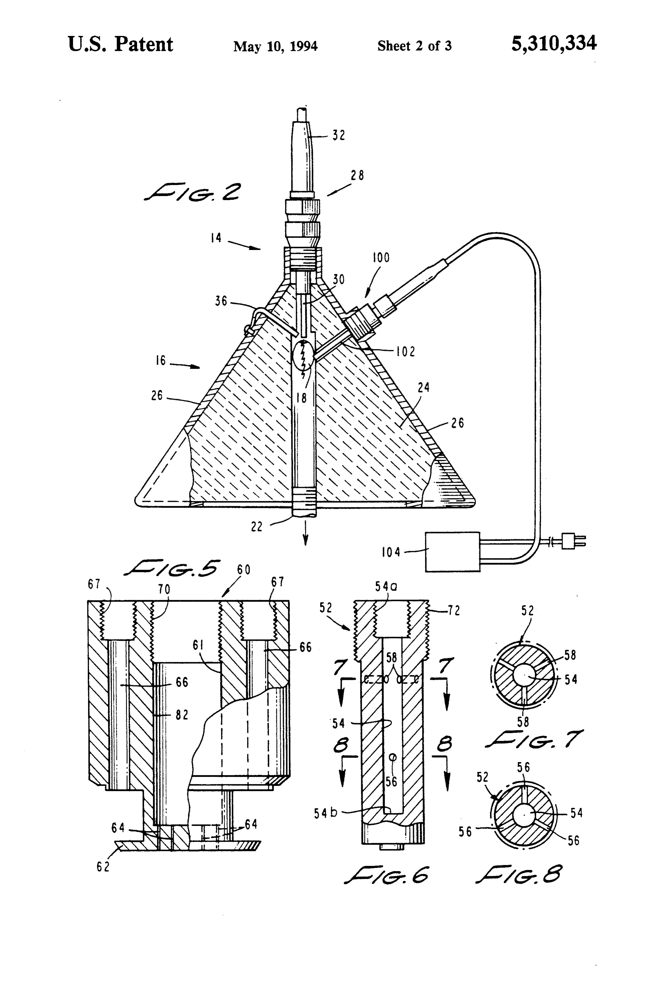
leased as heat through a number of complex chemical FIG. 4 is a cross-sectional view taken along lines 4-4 reactions and results in an extremely high flame temper of FIG. 3.
Page 6
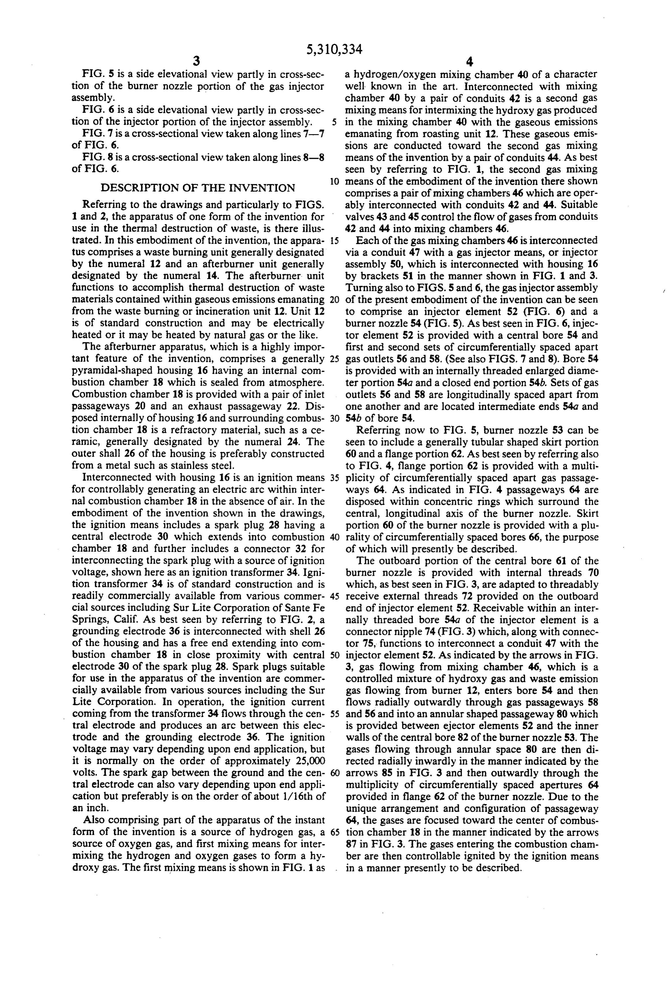
FIG. 5 is a side elevational view partly in cross-sec a hydrogen/oxygen mixing chamber 40 of a character tion of the burner nozzle portion of the gas injector well known in the art. Interconnected with mixing assembly. chamber 40 by a pair of conduits 42 is a second gas FIG. 6 is a side elevational view partly in cross-sec mixing means for intermixing the hydroxy gas produced tion of the injector portion of the injector assembly. in the mixing chamber 40 with the gaseous emissions FIG. 7 is a cross-sectional view taken along lines 7-7 emanating from roasting unit 12. These gaseous emis of F.G. 6. sions are conducted toward the second gas mixing FIG. 8 is a cross-sectional view taken along lines 8-8 means of the invention by a pair of conduits 44. As best of FIG. 6. seen by referring to FIG. 1, the second gas mixing 10 means of the embodiment of the invention there shown
DESCRIPTION OF THE INVENTION comprises a pair of mixing chambers 46 which are oper Referring to the drawings and particularly to FIGS. ably interconnected with conduits 42 and 44. Suitable 1 and 2, the apparatus of one form of the invention for valves 43 and 45 control the flow of gases from conduits use in the thermal destruction of waste, is there illus 42 and 44 into mixing chambers 46. trated. In this embodiment of the invention, the appara 5 Each of the gas mixing chambers 46 is interconnected tus comprises a waste burning unit generally designated via a conduit 47 with a gas injector means, or injector by the numeral 12 and an afterburner unit generally assembly 50, which is interconnected with housing 16 designated by the numeral 14. The afterburner, unit by brackets 51 in the manner shown in FIG. 1 and 3. functions to accomplish thermal destruction of waste Turning also to FIGS. 5 and 6, the gas injector assembly materials contained within gaseous emissions emanating of the present embodiment of the invention can be seen from the waste burning or incineration unit 12. Unit 12 to comprise an injector element 52 (FIG. 6) and a is of standard construction and may be electrically burner nozzle 54 (FIG. 5). As best seen in FIG. 6, injec heated or it may be heated by natural gas or the like. tor element 52 is provided with a central bore 54 and The afterburner apparatus, which is a highly impor first and second sets of circumferentially spaced apart tant feature of the invention, comprises a generally 25 gas outlets 56 and 58. (See also FIGS. 7 and 8). Bore 54 pyramidal-shaped housing 16 having an internal com is provided with an internally threaded enlarged diame bustion chamber 18 which is sealed from atmosphere. ter portion 54a and a closed end portion 54b. Sets of gas Combustion chamber 18 is provided with a pair of inlet outlets 56 and 58 are longitudinally spaced apart from passageways 20 and an exhaust passageway 22. Dis one another and are located intermediate ends 54a and posed internally of housing 16 and surrounding combus 30 54b of bore 54.
tion chamber 18 is a refractory material, such as a ce Referring now to FIG. 5, burner nozzle 53 can be ramic, generally designated by the numeral 24. The seen to include a generally tubular shaped skirt portion outer shall 26 of the housing is preferably constructed 60 and a flange portion 62. As best seen by referring also from a metal such as stainless steel. to FIG. 4, flange portion 62 is provided with a multi Interconnected with housing 16 is an ignition means 35 plicity of circumferentially spaced apart gas passage for controllably generating an electric arc within inter ways 64. As indicated in FIG. 4 passageways 64 are nal combustion chamber 18 in the absence of air. In the disposed within concentric rings which surround the embodiment of the invention shown in the drawings, central, longitudinal axis of the burner nozzle. Skirt the ignition means includes a spark plug 28 having a portion 60 of the burner nozzle is provided with a plu central electrode 30 which extends into combustion rality of circumferentially spaced bores 66, the purpose chamber 18 and further includes a connector 32 for of which will presently be described. interconnecting the spark plug with a source of ignition The outboard portion of the central bore 61 of the voltage, shown here as an ignition transformer 34. Igni burner nozzle is provided with internal threads 70 tion transformer 34 is of standard construction and is which, as best seen in FIG. 3, are adapted to threadably readily commercially available from various commer 45 receive external threads 72 provided on the outboard cial sources including Sur Lite Corporation of Sante Fe end of injector element 52. Receivable within an inter Springs, Calif. As best seen by referring to FIG. 2, a nally threaded bore 54a of the injector element is a grounding electrode 36 is interconnected with shell 26 connector nipple 74 (FIG.3) which, along with connec of the housing and has a free end extending into com tor 75, functions to interconnect a conduit 47 with the bustion chamber 18 in close proximity with central SO injector element 52. As indicated by the arrows in FIG. electrode 30 of the spark plug 28. Spark plugs suitable 3, gas flowing from mixing chamber 46, which is a for use in the apparatus of the invention are commer controlled mixture of hydroxy gas and waste emission cially available from various sources including the Sur gas flowing from burner 12, enters bore 54 and then Lite Corporation. In operation, the ignition current flows radially outwardly through gas passageways 58 coming from the transformer 34 flows through the cen 55 and 56 and into an annular shaped passageway 80 which tral electrode and produces an arc between this elec is provided between ejector elements 52 and the inner trode and the grounding electrode 36. The ignition walls of the central bore 82 of the burner nozzle 53. The voltage may vary depending upon end application, but gases flowing through annular space 80 are then di it is normally on the order of approximately 25,000 rected radially inwardly in the manner indicated by the volts. The spark gap between the ground and the cen 60 arrows 85 in FIG. 3 and then outwardly through the tral electrode can also vary depending upon end appli multiplicity of circumferentially spaced apertures 64 cation but preferably is on the order of about 1/16th of provided in flange 62 of the burner nozzle. Due to the an inch. unique arrangement and configuration of passageway Also comprising part of the apparatus of the instant 64, the gases are focused toward the center of combus form of the invention is a source of hydrogen gas, a 65 tion chamber 18 in the manner indicated by the arrows source of oxygen gas, and first mixing means for inter 87 in FIG. 3. The gases entering the combustion cham mixing the hydrogen and oxygen gases to form a hy ber are then controllable ignited by the ignition means droxy gas. The first mixing means is shown in FIG. 1 as in a manner presently to be described.
Page 7
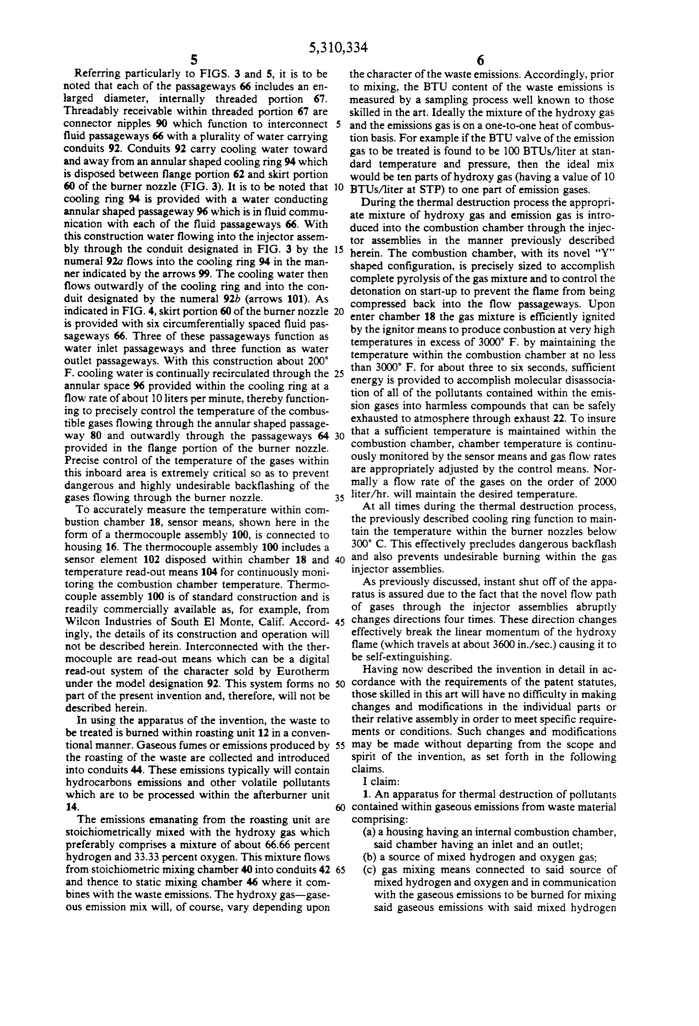
Referring particularly to FIGS. 3 and 5, it is to be the character of the waste emissions. Accordingly, prior noted that each of the passageways 66 includes an en to mixing, the BTU content of the waste emissions is larged diameter, internally threaded portion 67. measured by a sampling process well known to those Threadably receivable within threaded portion 67 are skilled in the art. Ideally the mixture of the hydroxy gas connector nipples 90 which function to interconnect and the emissions gas is on a one-to-one heat of combus fluid passageways 66 with a plurality of water carrying tion basis. For example if the BTU valve of the emission conduits 92. Conduits 92 carry cooling water toward gas to be treated is found to be 100 BTUs/liter at stan and away from an annular shaped cooling ring 94 which dard temperature and pressure, then the ideal mix is disposed between flange portion 62 and skirt portion would be ten parts of hydroxy gas (having a value of 10 60 of the burner nozzle (FIG. 3). It is to be noted that O BTUs/liter at STP) to one part of emission gases. cooling ring 94 is provided with a water conducting During the thermal destruction process the appropri annular shaped passageway 96 which is in fluid commu ate mixture of hydroxy gas and emission gas is intro nication with each of the fluid passageways 66. With duced into the combustion chamber through the injec this construction water flowing into the injector assem tor assemblies in the manner previously described bly through the conduit designated in FIG. 3 by the 15 herein. The combustion chamber, with its novel "Y' numeral 92a flows into the cooling ring 94 in the man shaped configuration, is precisely sized to accomplish ner indicated by the arrows 99. The cooling water then complete pyrolysis of the gas mixture and to control the flows outwardly of the cooling ring and into the con detonation duit designated by the numeral 92b (arrows 101). As compressedonback start-up to prevent the flame from being into the flow passageways. Upon indicated in FIG. 4, skirt portion 60 of the burner nozzle enter chamber 18 the gas mixture is efficiently ignited
is provided with six circumferentially spaced fluid pas sageways 66. Three of these passageways function as by the ignitor means to produce conbustion at very high temperatures in excess of 3000 F. by maintaining the water inlet passageways and three function as water temperature within the combustion chamber at no less outlet passageways. With this construction about 200 than 3000 F. for about three to six seconds, sufficient F. cooling water is continually recirculated through the 25 energy is provided to accomplish molecular disassocia annular space 96 provided within the cooling ring at a tion of all of the pollutants contained within the emis flow rate of about 10 liters per minute, thereby function sion gases into harmless compounds that ing to precisely control the temperature of the combus exhausted to atmosphere through exhaust can 22. To be safely insure tible gases flowing through the annular shaped passage that a sufficient temperature is maintained within the way 80 and outwardly through the passageways 64 provided in the flange portion of the burner nozzle. combustion chamber, chamber temperature is continu Precise control of the temperature of the gases within ously monitored by the sensor means and gas flow rates this inboard area is extremely critical so as to prevent are appropriately adjusted by the control means. Nor dangerous and highly undesirable backflashing of the mally a flow rate of the gases on the order of 2000 gases flowing through the burner nozzle. 35 liter/hr. will maintain the desired temperature. To accurately measure the temperature within com At all times during the thermal destruction process, bustion chamber 18, sensor means, shown here in the the previously described cooling ring function to main form of a thermocouple assembly 100, is connected to tain the temperature within the burner nozzles below housing 16. The thermocouple assembly 100 includes a 300 C. This effectively precludes dangerous backflash sensor element 102 disposed within chamber 18 and 40 and also prevents undesirable burning within the gas temperature read-out means 104 for continuously moni injector assemblies.
toring the combustion chamber temperature. Thermo As previously discussed, instant shut off of the appa couple assembly 100 is of standard construction and is ratus is assured due to the fact that the novel flow path readily commercially available as, for example, from of gases through the injector assemblies abruptly Wilcon Industries of South El Monte, Calif. Accord 45 changes directions four times. These direction changes ingly, the details of its construction and operation will effectively break the linear momentum of the hydroxy not be described herein. Interconnected with the ther flame (which travels at about 3600 in./sec.) causing it to mocouple are read-out means which can be a digital be self-extinguishing.
read-out system of the character sold by Eurotherm Having now described the invention in detail in ac under the model designation 92. This system forms no SO cordance with the requirements of the patent statutes, part of the present invention and, therefore, will not be those skilled in this art will have no difficulty in making described herein. changes and modifications in the individual parts or In using the apparatus of the invention, the waste to their relative assembly in order to meet specific require be treated is burned within roasting unit 12 in a conven ments or conditions. Such changes and modifications tional manner. Gaseous fumes or emissions produced by 55 may be made without departing from the scope and the roasting of the waste are collected and introduced spirit of the invention, as set forth in the following into conduits 44. These emissions typically will contain claims.
hydrocarbons emissions and other volatile pollutants I claim:
which are to be processed within the afterburner unit 1. An apparatus for thermal destruction of pollutants 14. contained within gaseous emissions from waste material The emissions emanating from the roasting unit are comprising:
stoichiometrically mixed with the hydroxy gas which (a) a housing having an internal combustion chamber, preferably comprises a mixture of about 66.66 percent said chamber having an inlet and an outlet; hydrogen and 33.33 percent oxygen. This mixture flows (b) a source of mixed hydrogen and oxygen gas; from stoichiometric mixing chamber 40 into conduits 42 65 (c) gas mixing means connected to said source of and thence to static mixing chamber 46 where it com mixed hydrogen and oxygen and in communication bines with the waste emissions. The hydroxy gas-gase with the gaseous emissions to be burned for mixing ous emission mix will, of course, vary depending upon said gaseous emissions with said mixed hydrogen
Page 8
and oxygen to produce a gaseous mixture, said (e) ignition means connected to said housing for con mixing means having an outlet; trollably generating an electrical spark within said (d) a gas injector assembly mounted on said housing, internal combustion chamber; and said gas injector assembly having an inlet in com (f) cooling means for controllably cooling said gas munication with said outlet of said gas mixing 5 injector assembly, said cooling means comprising means and an outlet in communication with said an annular shaped ring surrounding said burner inlet of said internal combustion chamber; nozzle, said ring having a water inlet and a water (e) ignition means connected to said housing for con outlet.
trollably generating an electrical spark within said 10 8. An apparatus as defined in claim 7 in which said internal combustion chamber; and . injector element is provided with a central bore defin (f) cooling means for controllably cooling said gas ing a wall and in which said gas outlets extend through injector assembly. said wall at circumferentially spaced apart location. 2. An apparatus as defined in claim 1 in which said 9. An apparatus as defined in claim 8 in which said combustion chamber is generally "Y" shaped in cross 5 gas passageways in said flange portion of said burner nozzle are circumferentially spaced apart along concen section and is surrounded by a refractory material.
3. An apparatus as defined in claim 1 in which said tric10.rings surrounding the center of said flange. gas injector assembly comprises an injector and a skirt portion of saidas burner
An apparatus defined in claim 9 in which said nozzle is provided with burner nozzle and in which said cooling means com circumferentially prises an annular shaped ring surrounding said burner 20 passageways in communication inlet spaced water and water outlet nozzle, said ring having a water inlet and a water outlet. water inlet and said water outlet respectively of said with said annular shaped 4. An apparatus as defined in claim 1 in which said ring.
burner nozzle comprises: 11. An apparatus for treatment of waste materials (a) a body portion provided with a central bore and at comprising:
least two circumferentially spaced bores; and 25 (a) a burner means for burning the waste materials to (b) a flange portion integrally formed with said body produce combustion emission gases, said burner portion, said flange having a multiplicity of gas means having an emission gas outlet; passageways in communication with said central (b) a housing having an internal combustion chamber, bore of said body portion. said chamber having an inlet and an outlet; 5. An apparatus as defined in claim 4 in which said 30 (c) a source of mixed hydrogen and oxygen gas; injector is mounted within said central bore of said body (d) gas mixing means connected to said source of portion and includes a generally cylindrically shaped mixed hydrogen and oxygen and in communication body having a skirt portion provided with a plurality of with said emission gas outlet of said burner means circumferentially spaced gas passageways in communi for mixing said emissions with said mixed hydrogen cation with said central bore of said body portion of said 35 and oxygen to produce a gaseous mixture, said burner nozzle. mixing means having an outlet; 6. An apparatus as defined in claim 4 in which said (e) a gas injector assembly mounted on said housing, cooling means comprises an annular shaped ring sur said gas injector assembly having an inlet in com rounding said burner nozzle, said ring having a water munication with said outlet of said gas mixing inlet and a water outlet and in which said circumferen 40 means and an outlet in connunication with said tially spaced bores of said body portion of said burner inlet of said internal combustion chamber; nozzle are in communication with said water inlet and (f) arc producing means connected to said housing for said water outlet of said annular shaped ring. controllably generating an electrical arc within 7. An apparatus for thermal destruction of contami- 45 said internal combustion chamber; and nates contained within combustion emissions from (g) cooling means for controllably cooling said gas waste material comprising: injector assembly, said cooling means comprising (a) a housing having an internal combustion chamber, an annular shaped ring connected to said injector said chamber having an inlet and an outlet; assembly, said ring having a water inlet and a water outlet.
(b) a source of mixed hydrogen and oxygen gas; 50 12. An apparatus as defined in claim 11 in which said (c) gas mixing means connected to said source of gas injector mixed hydrogen and oxygen and in communication burner nozzle,assembly said comprises an injector and a burner nozzle comprising:
with the combustion emissions for mixing said (a) a body portion provided with a central bore and at emissions with said mixed hydrogen and oxygen to produce a gaseous mixture, said mixing means hav 55 (b) a flange portion integrally spaced least two circumferentially formed bores; and with said body ing an outlet; portion, said flange having a multiplicity of gas (d) a gas injector assembly mounted on said housing, passageways in communication with said central said gas injector assembly comprising: bore of said body portion.
(i) an injector element having an inlet in communi 13. An apparatus as defined in claim 12 in which said cation with said outlet of said gas mixing means injector is mounted within said central bore of said body and having a plurality of gas outlets; and portion and includes a generally cylindrically shaped (ii) a burner nozzle having a generally tubular body having a skirt portion provided with a plurality of shaped skirt portion adapted to receive said in circumferentially spaced gas passageways in communi jector element and a flange portion provided cation with said central bore of said body portion of said with a plurality of gas passageways in communi 65 burner nozzle.
cation with said gas outlets of said injector ele 14. A method for treating waste materials in an appa ment and also in communication with said com ratus of the character having a combustion chamber, bustion chamber; gas mixing means for mixing the waste material with
Page 9
hydrogen and oxygen gas, an injector means for inject ignition means to cause said gaseous mixture to ing the mixture into the chamber and an electric arc burn at an elevated temperature in excess of 3,000 ignition means for igniting a gaseous mixture within the degrees Fahrenheit.
chamber, the method comprising the steps of: 15. A method as defined in claim 14 in which said (a) burning the waste materials to produce gaseous 5 gaseous mixture is ignited by the electrical arc in the emissions; absence of air.
(b) mixing said gaseous emissions with a mixture of 16. A method as defined in claim 15 in which the hydrogen and oxygen to produce a gaseous mix apparatus further includes means for cooling the gas ture; and injector means and in which the method comprises the (c) introducing said gaseous mixture into the combus 10 further step of cooling the injector means during the tion chamber via the injection means and igniting step of burning said s:gaseous mixture. said gaseous mixture with the electrical arc of the
Provenance
- Collection
- Patents citing this work
- Current assignee
- AUSTRALIAN THERMAL TECHNOLOGIES Ltd
- Original assignee
- Air Duke Australia Ltd
- Pages
- 9
- Method
- pdftotext (the PDF's own text layer) + pdftoppm 300dpi page scans
- Patent office record
- patents.google.com →
- Source
- Google Patents citing-documents table
- Inventors
- Spiro Spiros; Air Duke Australia Ltd
- Published
- 1994-05-10
- Transcribed from
- patentimages.storage.googleapis.com →