patent · US5763189
Fluorescence energy transfer and intramolecular energy transfer in particles using novel compounds
9 June 1998
Page 1 — bibliographic record
United States Patent (19) 11 Patent Number: 5,763,189 Buechler et al. 45) Date of Patent: Jun. 9, 1998 54 FLUORESCENCE ENERGY TRANSFER AND 5,055,414 10/1991 Babb et al. ............................. 436/SO1 NTRAMOLECULAR ENERGY TRANSFER 5, 16.989 5/1992 Hale et al. ....... ... 546,265 N PARTICLES USING NOVELCOMPOUNDS 5,123,731 6/1992 Yoshinaga et al. ... 356/3 5,132.206 7/1992 Dreyer ............. ... 435/6 75 Inventors: Kenneth F. Buechler, San Diego; J. 5,154,887 0/1992 Babb ......................................... 422/56 5,157,412 10/1992 Kleinschmidt et al. ... 34.6/.
Barry Noar, Solana Beach; Lema 5,194,393 3/1993 Hugi et al. ............ ... 436525 Tadesse. San Diego, all of Calif. 5,326,692 7/1994 Brinkley et al. ............................ 435/6 73 Assignee: Biosite Diagnostics Incorporated, San FOREIGN PATENT DOCUMENTS Diego, Calif. 075982 4/1983 European Pat. Off. .
21 Appl. No.: 311,098 0407188A1 i? 1991 European Pat. Off. .
OTHER PUBLICATIONS
Related U.S. Application Data
Pekcan, O. et al. "Direct Energy Transfer Studies on Doped 63 Continuation-in-part of Ser. No. 274,534, Jul. 12, 1994, and and Labelled Polymer Latex Particles" Physical Review a continuation-in-part of Ser. No. 138,708, Oct. 18, 1993, Letters 61:641-644 (Aug. 1, 1988).
abandoned, and a continuation-in-part of Ser. No. 126,367, Stryer, Lubert, "Fluorescent Energy Transfer As A Spectro Sep. 24, 1993, abandoned. scopic Ruler” Ann. Rev. Biochem. 45: 819-46 (1978). (51) Int. Cl. ..................... G01N 33/542; G01N 33.543: Molecular Probes Ad entitled "Novel Fluorescent Latex CO9K 9/00; CO9K 9/02 Microspheres-Tranfluospheres A Breakthrough in Latex 52 U.S. Cl. ................................ 435/7.1: 435/6; 435/7.5; Microsphere Technology (1994)".
435/7.92; 436/510; 436/528: 436/529; 436/530; Primary Examiner-Lora M. Green 436/531; 436/546; 436/800; 427/213.34; Attorney, Agent, or Firm-Lyon & Lyon LLP
58) Field of Search ............................... 435/6, 7.1, 7.5, Particles comprising an energy donor as a first component 435/7.92; 436/518, 528, 529, 530, 531, and a fluorescent dye as a second component positioned in 546, 800; 427/213.34, 157: 428/402.24. said particles at an energy exchanging distance from one 407; 252/301.34, 301.35 another, wherein the two components have a Stokes shift of 56 References Cited greater than or equal to 50 nm, said particle having bound on its surface, a protein, polypeptide, nucleic acid, nucleotide or
3.996,345 12/1976 Ullman et al. ............................ 424/2 claimed. In addition, novel fluorescent dyes are described 4.166,105 8/1979 Hirschfield .................................. 424/8 which exhibit intramolecular energy transfer for use to label 4,199,559 4/980 Ulman et al. .. . 424/8 various molecules, proteins, polypeptides, nucleotides and 4.542,104 9/1985 Stryer et al. 436,536 nucleic acids or to incorporate into particles. 4,666,862 5/1987 Chan ....................................... 436/SO1 4,777,128 10/1988 Lippa .......................................... 435/5 5 Claims, 8 Drawing Sheets
Page 2
Drawing sheet — no readable text.
Page 3
Drawing sheet — no readable text.
Page 4
Drawing sheet — no readable text.
Page 5
Drawing sheet — no readable text.
Page 6
ATTENUATION OF BACKGROUND SIGNAL BY BANDPASS-FILTERS
LLUMINATION SOURCE IS 1 mW 670 nm LASER DODE
DEVICE
WITH SERUM
WITHOUT SERUM
720 74O 760 780 800 820 84O 860 880 900 920
CENTER WAVELENGTH OF
BAND PASS FILTER, nm (A) = 12nm)
Page 7
Drawing sheet — no readable text.
Page 8
Drawing sheet — no readable text.
Page 9
Drawing sheet — no readable text.
Page 10
FLUORESCIENCE ENERGY TRANSFER AND however, the use of filters decreases the yield of light INTRAMOLECULAR ENERGY TRANSFER reaching the detector and generally one circumvents this N PARTICLES USING NOVELCOMPOUNDS problem of light loss by the use of high intensity lamps. Thus, to avoid problems associated with small Stokes shifts
This application is a continuation in part of application 5 and dyes which emit near the intrinsic emission of the Ser. No. 08/274,534 filed Jul. 12, 1994 and of application biological fluid, a sophisticated instrument is generally built. With the advent of near-patient diagnostics in hospitals.
application Ser. No. 08/126,367 filed Sep. 24, 1993 now instruments more which are used for the diagnostics will become portable and simpler to use. Therefore, there is a need abandoned from which priority is claimed. All of these for portable, simple fluorometers which can assess fluores applications are hereby fully incorporated by reference cence in an immunoassay
for the detection of analytes in herein. biological samples.
FIELD OF THE INVENTION Another problem associated with the assay of analytes in fluids or the visualization of cellular components with an
This invention relates generally to the synthesis of novel 15 intrinsic fluorescence is that of selection of the dye which is dyes and labels and methods for the detection or visualiza utilized as the label. The dye is generally chosen for its tion of analytes and more specifically to fluorescent latex brightness (the product of fluorescence quantum yield and particles which incorporate the novel fluorescent dyes and extinction coefficient) since a certain sensitivity in the assay utilize, in certain aspects, fluorescence energy transfer and or the visualization technique is required. However, the intramolecular energy transfer. for the detection of analytes selection of the dye used as the label is limited when the in immunoassays or in nucleic acid assays. sample has an intrinsic fluorescence because the instrument may not be capable of distinguishing sample fluorescence
BACKGROUND from dye fluorescence.
The current invention provides a methodology for the
Various methodologies are available for the visualization development of amplified fluorescent label systems which of cells or molecules in cells and for the measurement of 25 can be tuned to specific excitation and emission wave analyte concentrations in fluids. Fluorescence microscopy lengths. In addition, the methodology teaches improved utilizes fluorescent dyes, generally connected to specific methods for incorporation of dyes into particles to minimize probes, such as antibodies, for the localization of proteins fluorescence quenching and to maximize fluorescence inten and complexes in cells. For the measurement of analyte sities of the dye molecules in the particles. The novel dye concentrations, immunoassays have become popular over 30 systems can be utilized for the quantitation of analytes in the last 40 years because of the specificity of antibodies fluids, and in particular, in biological fluids. The novel dye toward the analyte or target ligand. Radioimmunoassays systems can be tuned to specific exciting and emitting were developed because the high specific activity of the wavelengths so that low current sources, such as light radionuclide allowed measurement of very low concentra emitting diodes and laser diodes, and detectors, such as tions of analyte. However, because of the concerns for the 35 photo diodes. and the like, can be used in the manufacture of fluorometers which can be battery powered and portable, environment and human health, the use of radionuclides in immunoassays is becoming less popular. The use of for use, for example, in immunoassays dedicated to near enzymes in immunoassays to amplify a signal has been a patient diagnostics.
very important advance in the field of immunoassays SUMMARY OF THE INVENTION because their use does not involve environmental or human This invention relates to novel fluorescent particles. These health hazards or risks. Enzyme-linked immunoassays. novel particles can however, can be problematic because the activity of the emission wavelengthsbetotuned to specific excitation and accommodate a wide variety of enzyme is temperature dependent and the instability of the assay or visualization systems. In yet another aspect of the enzyme or the substrates can result in inaccurate quantitation of the target ligand. Still other immunoassays monitor 45 invention, the methodology teaches improved methods for incorporation of dyes into particles to minimize fluorescence fluorescence as the signal, with or without enzymes, for the quenching and to maximize fluorescence intensities of the measurement of analyte concentrations. dye molecules in the particles through the use of different The characteristics of the fluorescent dyes are very impor dye molecules which possess the same or very similar tant when quantifying analyte concentrations in biological excitation and emission wavelengths.
fluids. For example, when the biological fluid is blood, 50 Many novel phthalocyanine derivatives and hybrid pha serum or plasma, the intrinsic fluorescence of the fluid precludes the use of many dyes. These biological fluids locyanine derivatives are disclosed and claimed. In one embodiment microparticles having at least one hybrid phtha generally have fluorescence emissions up to 600 nm when locyanine derivative, said derivative(s) having (1) at least exciting at various wavelengths above 200 nm. The fluo one donor subunit with a desired excitation peak; and (2) at rescence is generated by excitation of the dye at the appro 55 least one acceptor subunit with a desired emission peak, priate wavelength. The fluorescent signal is measured by a wherein said derivative(s) isfare capable of intramolecular fluorometer which is tuned to excite the fluorescent mol energy transfer from said donor subunit to said acceptor ecule at a specific wavelength and to measure the emission subunit are disclosed. Such derivatives also may contain an of fluorescence at another wavelength. The difference in the electron transfer subunit. Axial ligands may be covalently excitation and emission wavelengths is referred to as the bound to the metals contained in the hybrid phthalocyanine Stokes shift. To achieve the most sensitive measurement, the derivatives. Numerous compounds capable of intramolecu emission wavelength of the sample should not interfere with lar energy transfer as well as compounds for fluorescence the emission of the dye. Also, the Stokes shift should be as energy transfer are claimed.
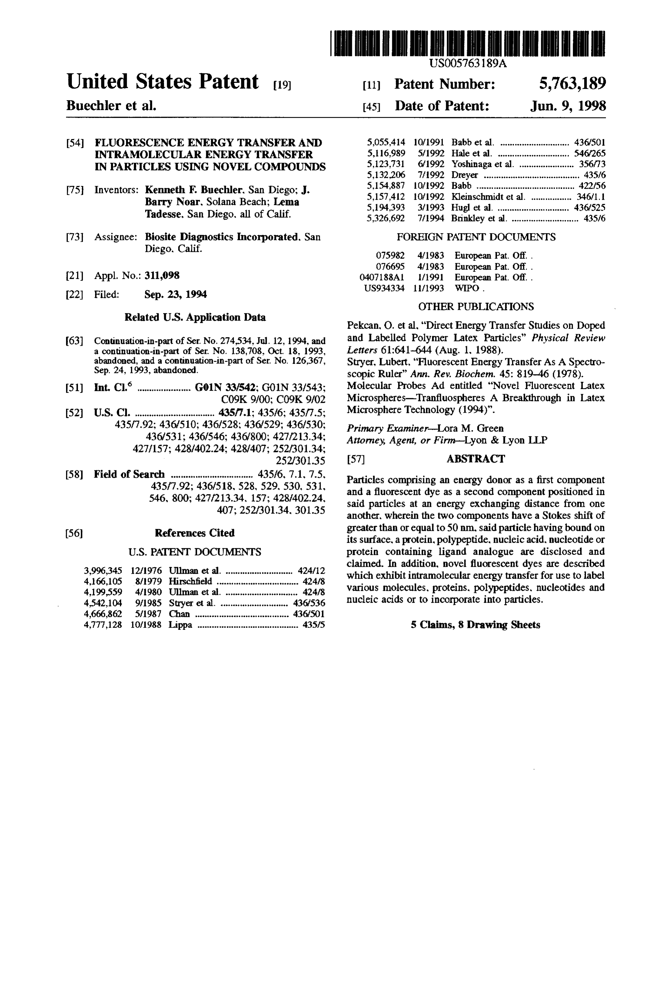
large as possible so that the excitation light is not seen by the detector as a background signal. When the Stokes shift is not 65 DESCRIPTION OF THE DRAWING large, filters or monochromators can be utilized in the FIG. 1 depicts the structures of phthalocyanine, naphtha fluorometer to exclude light near the emission wavelength; locyanine and anthranylocyanine.
Page 11
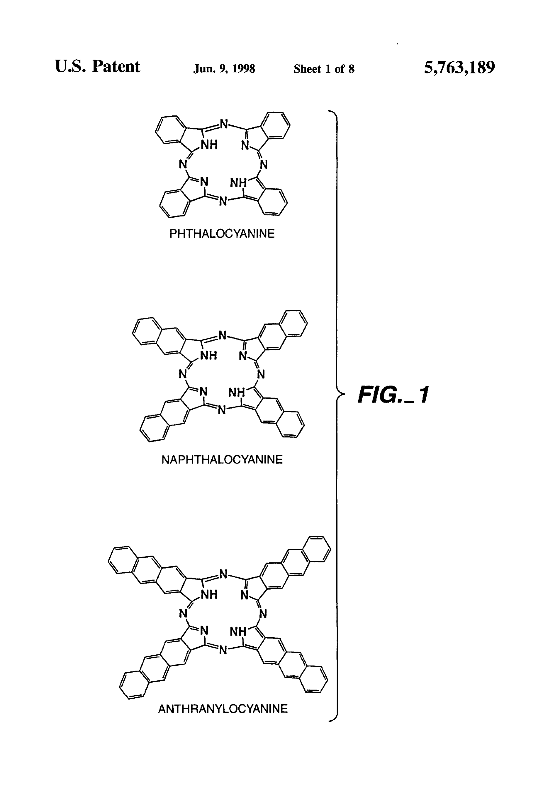
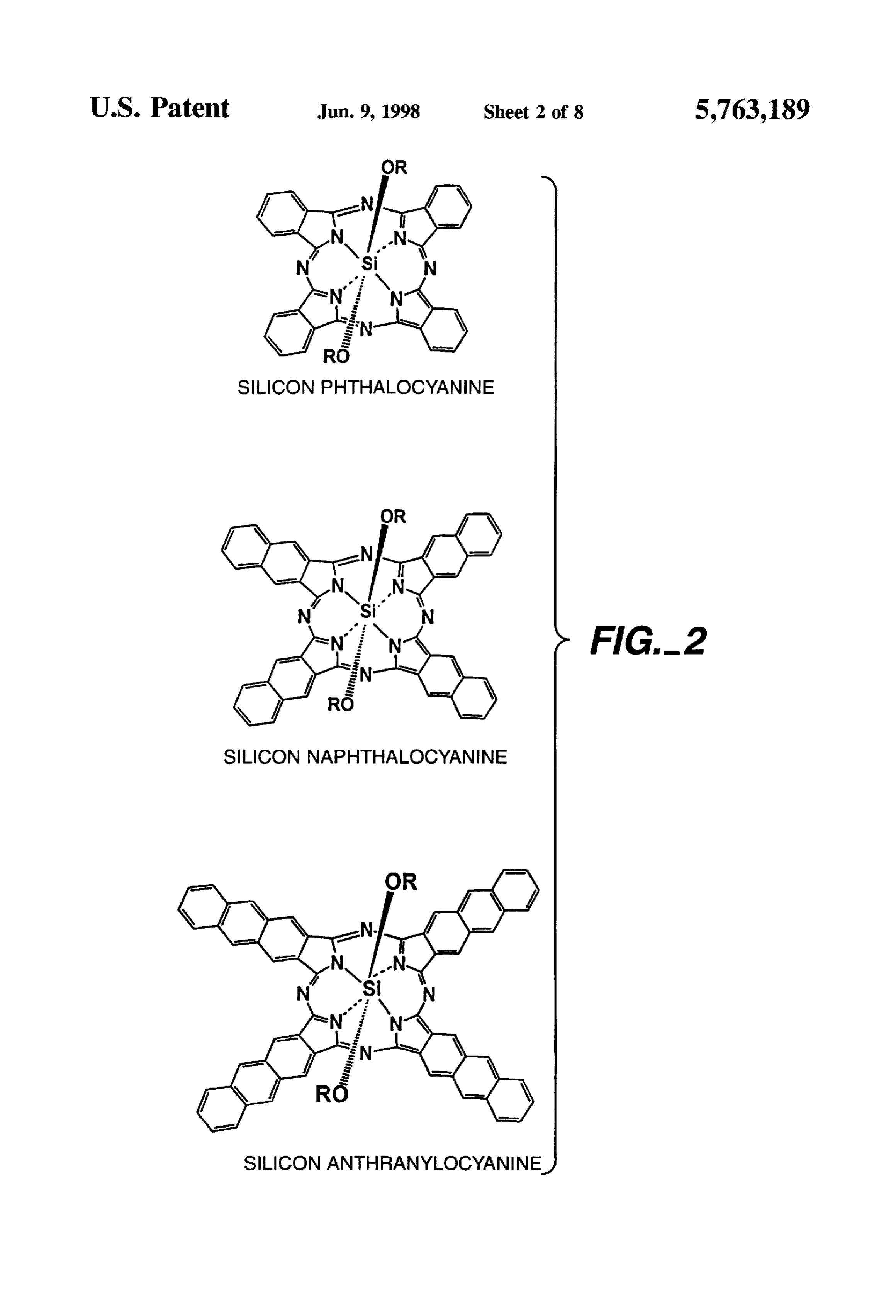
FIG. 2 depicts the structures of silicon phthalocyanine, possible rather than designing the instrument around the silicon naphthalocyanine and silicon anthranylocyanine. specifications of the dye. Tuning the dye system to accom FIG. 3 depicts the spectra of silicon phthalocyanine modate the characteristics of the sample and the instrument results in a much greater chance of success of the visual dihydroxide and the spectra of silicon 2.3-naphthalocyanine ization process or the assay.
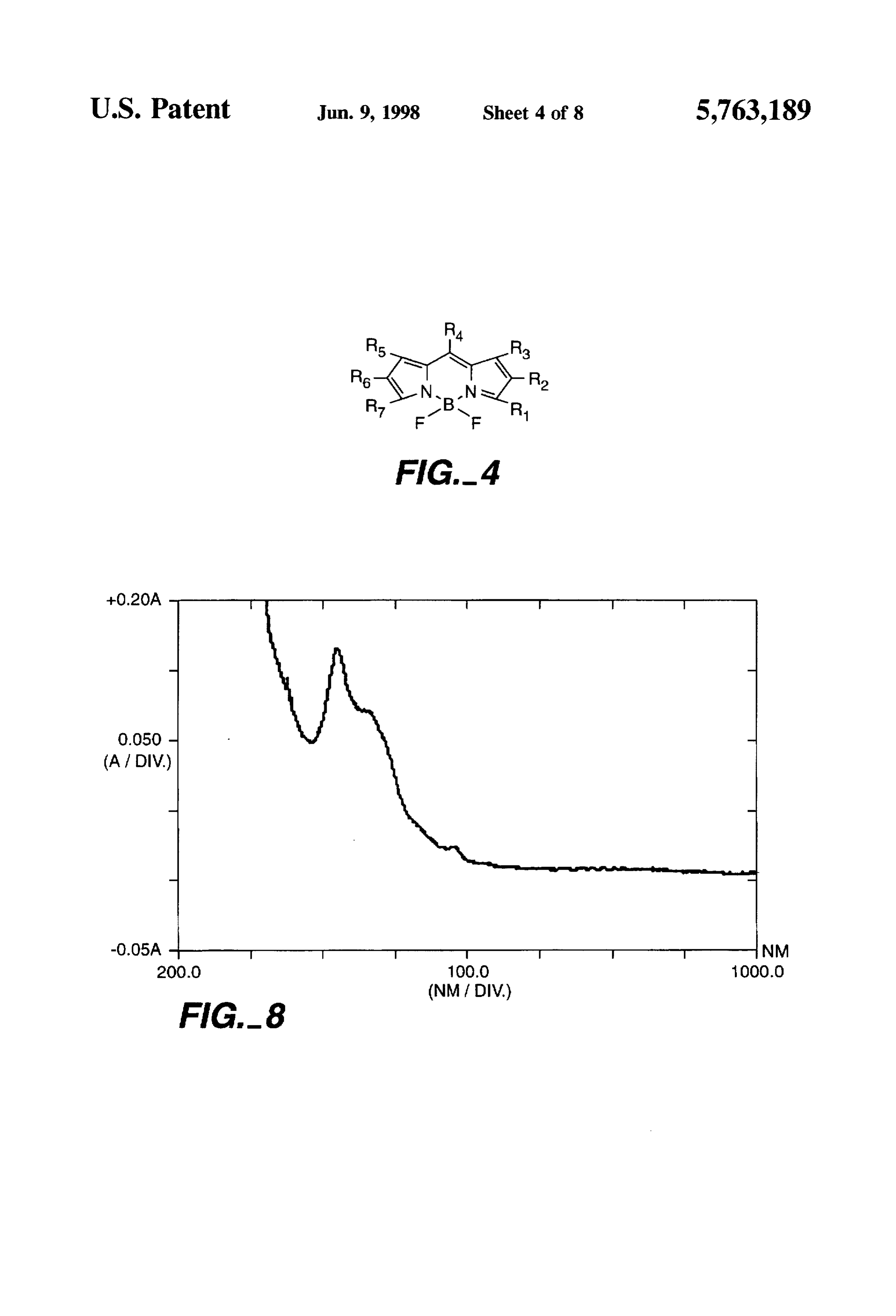
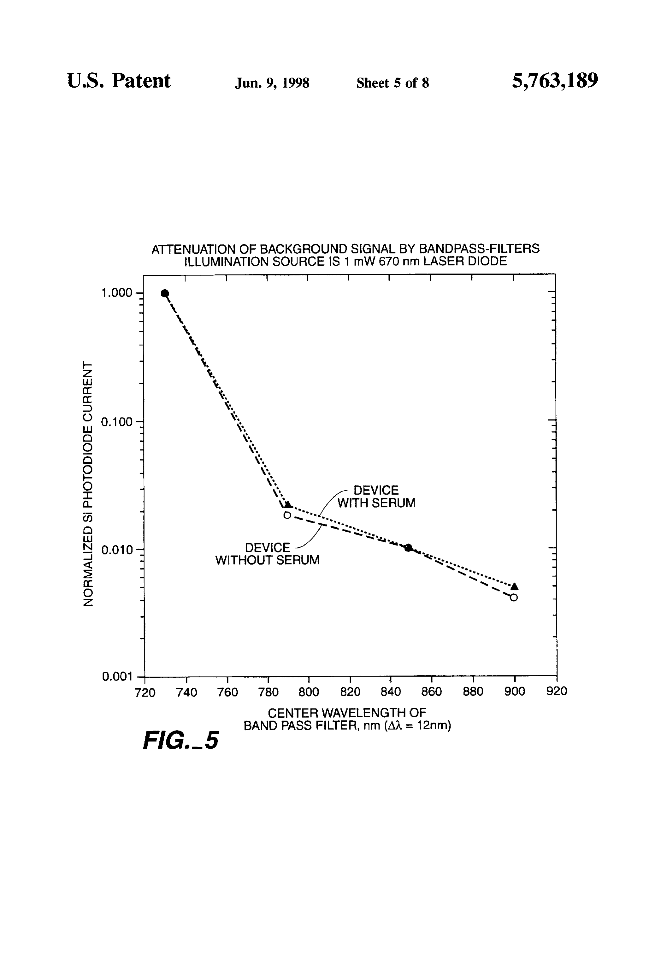
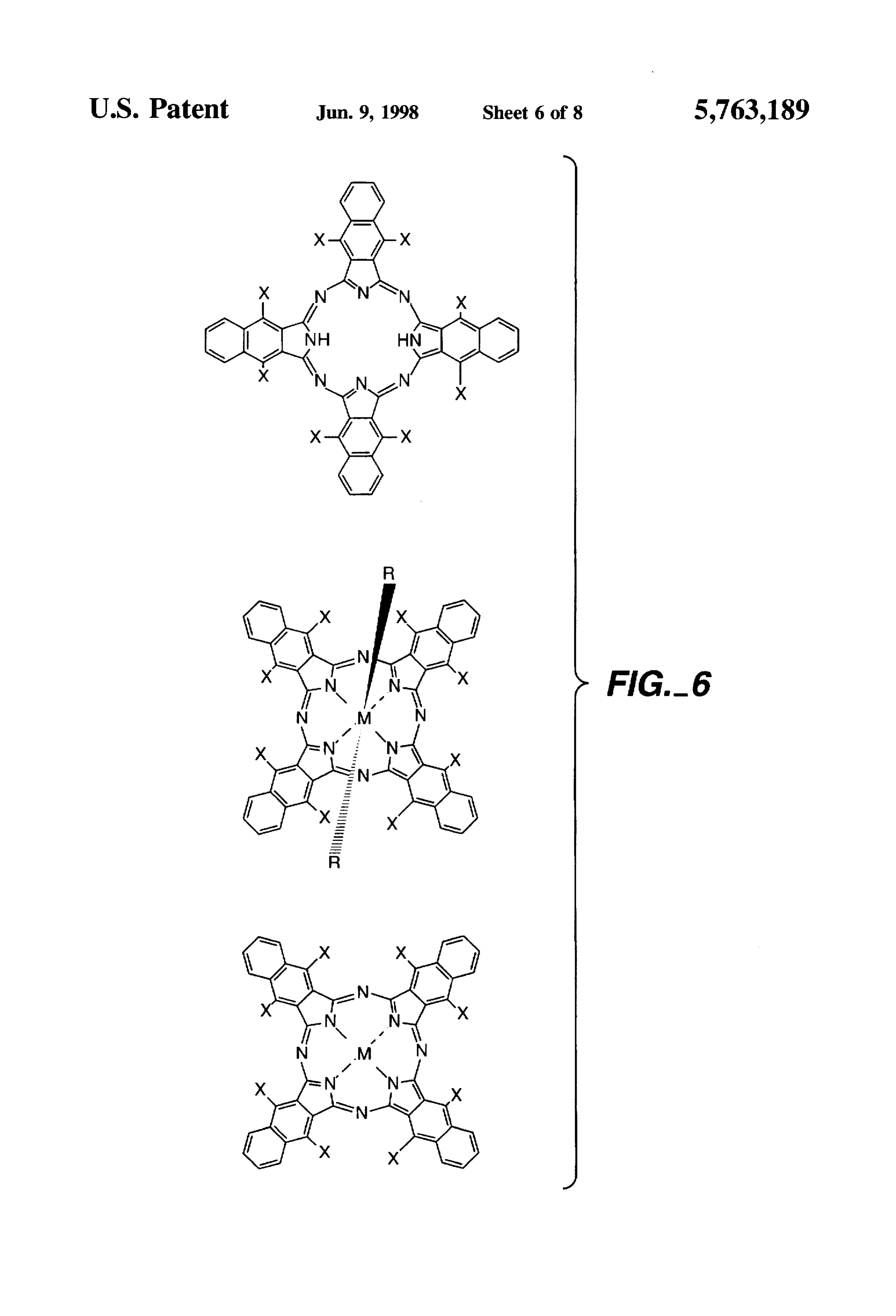
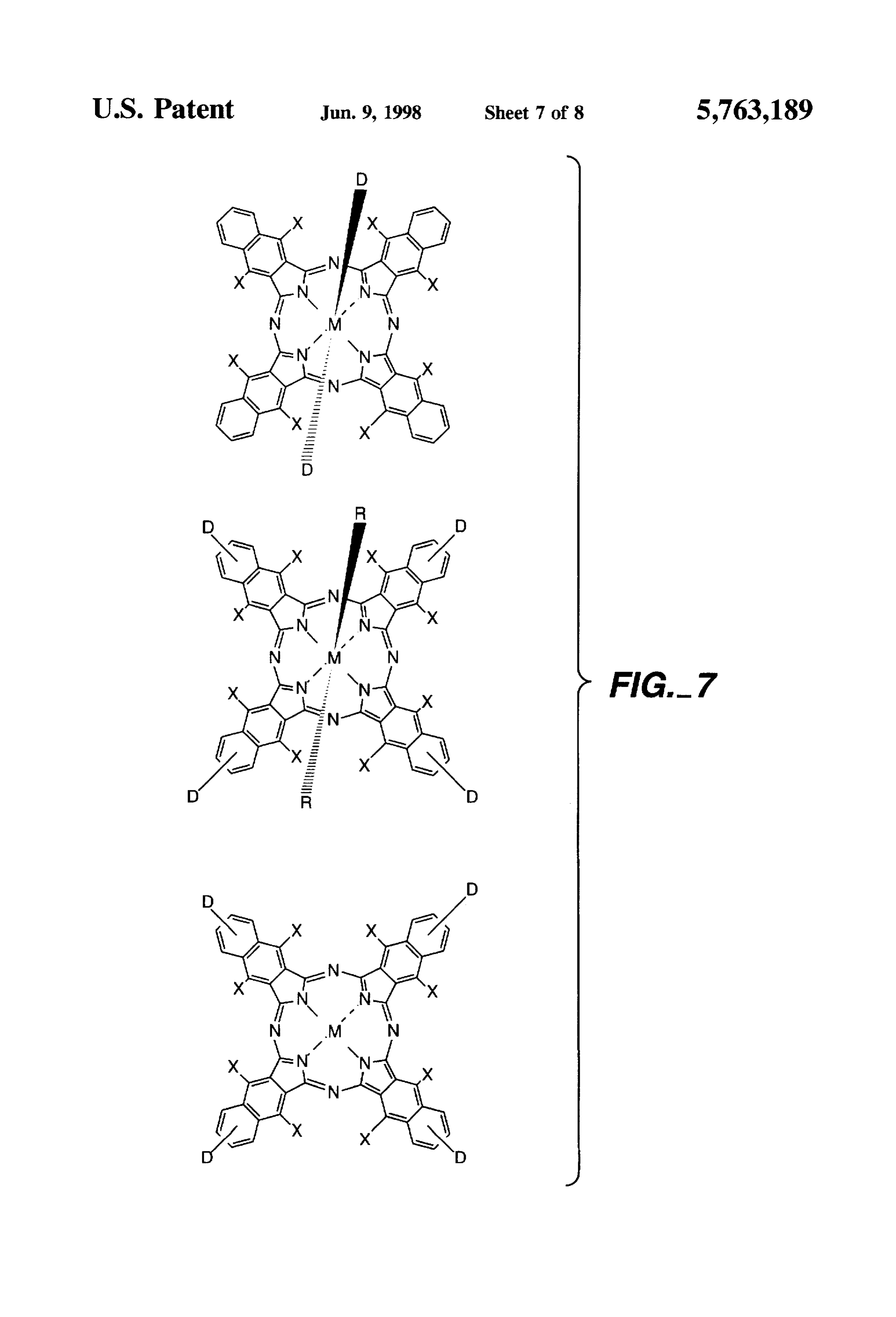
dihydroxide. The excitation and emission wavelengths of the dye FIG. 4 depicts the general structure of ethenyl-substituted should not correspond to those of the sample being assayed dipyrrometheneboron difluoro dyes. or visualized, otherwise the sample can interfere with the FIG.5 depicts the attenuation of the background signal as measurement of the fluorescent signal. When absorption or a function of increasing wavelength. The data was measured emission wavelengths of the sample do correspond to those using a device as described in Applicant's allowed Ser. No. of the dye, in practice, one dilutes. for example, a serum or 07/887,526 filed May 21, 1992 entitled "Diagnostic Devices blood sample so that the interference by the sample is and Apparatus for the Controlled Movements of Reagents reduced or the interfering sample is washed away from the Without Membranes.' now U.S. Pat. No. 5458,852 which is detection area. Indeed, currently on the market, no fluores hereby fully incorporated herein. 15 cent assay system exists for the measurement of analytes in FIG. 6 depicts naphthalocyanine derivatives which emit neat biological fluids, particularly blood or serum. One in the near infrared. reason for the lack of fluorescent assay systems which detect FIG. 7 depicts general structures of fluorescent energy analytes in neat samples is that no good fluorescent dye transfer naphthalocyanine compounds. exists which meets all the criteria listed above, particularly FIG. 8 depicts the absorbance spectrum of human serum for 20 measuring fluorescence in biological samples. When the sample absorbs significantly at the excitation wavelength the between 200 nm and 1000 nm.
amount of light which excites the sample is thus affected by
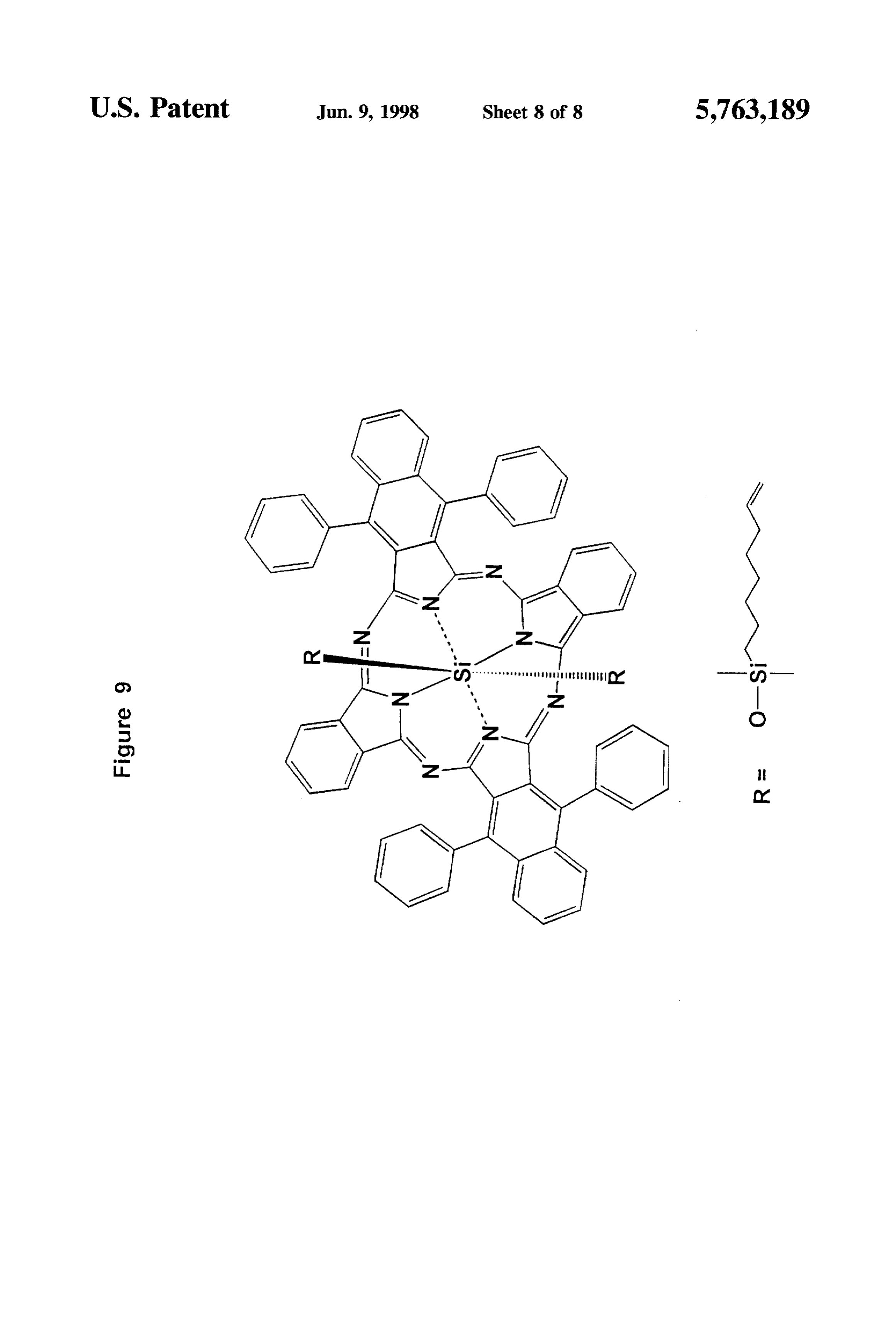
FIG. 9 depicts the structure of a novel hybrid phthalo the variation in the sample characteristics. For example. cyanine derivative, Silicon di(1.6- serum, plasma, or blood from different individuals will be diphenylnaphthalocyanine) diphthalo-cyanine bis 25 different in their relative absorptivities, which will translate (dimethylhexylvinylsilyloxide). into different intensities of excitation light used to excite the DETALED DESCRIPTION fluorescent label. The fluorescence emission of the dye is directly proportional to the intensity of the incident light,
This invention describes novel fluorescent particles and such that when the sample absorbs a portion of the incident novel fluorescent molecules and diagnostic methods for their 30 light, the intensity of the fluorescent signal will vary accord use. Developing a method for the visualization of a cellular ingly. This results in measuring an incorrect or effected component or a cell or for an assay which utilizes a fluorescence emission. In addition, the emission wavelength fluorescent dye and which quantifies an analyte in a sample of the dye should not correlate with the emission or absor requires the use of a fluorometer. The fluorescent label, the bance of the sample because the sample will increase the sample and the instrument must be compatible with each 35 measured fluorescence of the dye or the sample will absorb other to achieve an accurate measurement. Several criteria all or a portion of the dye fluorescence and also result in an for a fluorescent label as it relates to the sample and incorrect or effected fluorescence emission. These problems instrument are described below. First, the absorption or are avoided when the sample is invisible to the excitation excitation and emission wavelengths of the dye should not and emission wavelengths.
correspond to those of the specimen or sample. Second, the FIG. 8 shows the spectrum between 200 nm and 1000 nm. Stokes shift of the dye should be as large as possible to of human serum. Wavelengths above 600 nm absorb con minimize the measurement of background from the excita siderably less than those between 200 nm and 600 nm. Thus, tion wavelength. Third, the dye must be compatible with the both the absorption of the incident light and the effect on the phase of the visualization or the fluid phase of the assay; that fluorescence of a dye are minimal when exciting above 600 is, the dye must be water soluble or water insoluble depend 45 nm. Preferred excitation wavelengths for biological fluids, ing on the visualization or assay format. Fourth, the dye including urine, blood, serum or plasma is 600 nm or greater. should be as bright as is necessary to achieve the desired Particularly preferred excitation wavelengths above 600 nm sensitivity. Brightness is the product of the extinction coef are those which correspond to the maximum light output of ficient and the quantum yield of the dye. Fifth, the instru laser diodes and light emitting diodes. Preferred emission ment used to detect the fluorescent signal is generally 50 wavelengths are those above 600 nm. The intrinsic sample designed around the specifications of the dye and the speci fluorescence can cause a high background signal if the men or sample being visualized or assayed. emission wavelength of the dye and the sample are over These points will be discussed in more detail and illustrate lapping. In addition, the scattered light of the excitation some of the difficulties in developing a fluorescent visual source can also contribute to the background signal. The ization technique or an assay using fluorescent dyes. One is 55 contribution of the scattered light to the background can be limited either to dyes which have been synthesized or ones seen, for example, in FIG.5. In general, the magnitude of the which must be synthesized in order to meet the above scatter is inversely proportional to the fourth power of the criteria. Those skilled in the art will appreciate that the measured wavelength. This teaches that desired emission design and synthesis of dye molecules which have a very wavelengths are in the near-infrared or in the infrared region broad range of excitation and emission wavelengths is very of the spectrum. The inventive teachings described herein tedious and generally, only a very limited range of excitation provide for dyes and dye systems which excite above 600 and emission wavelengths can be planned for a specific nm and which emit above 650 nm and more preferred above molecule. The teachings of this invention allow one to 730 nm.
prepare fluorescent labels which can be tuned to many The Stokes shift of the dye should be as large as possible excitation and emission wavelengths allowing for large 65 to minimize the measurement of background from the Stokes shifts. Thus, designing a dye system with the speci excitation source so that the signal-to-background ratio at fications of the sample or specimen and the instrument is the limit of sensitivity is maximized. A large Stokes shift,
Page 12
however, will only maximize the efficiency of the fluores wavelengths of the novel fluorescent particles can generally cence measurement and may not always result in an accurate be varied independently of each other. fluorescence measurement. For example, table 3 shows data The dye must be compatible with the fluid phase of the from several dye systems which were excited between 420 nm and 670 nm in either buffer or undiluted human serum. 5 assay, or in other words, the dye must be water soluble or water insoluble depending on the visualization or assay
The fluorescence intensity of the first dye system (from line format.
1. table 1), when excited at 475 nm in serum, is only 7.6% water soluble Many fluorescent dyes are water insoluble or poorly and these dyes are not easily used for labelling of the intensity in buffer even though the Stokes shift is 205 molecules, proteins, nm. The second dye system (from line 4, table 1), excited at art will recognize thatnucleic acids or cells. One skilled in the water insoluble dyes can be incorpo 420 nm, is 28% of the intensity in buffer with a 260 nm O rated into latex particles as described in U.S. Pat. Nos. Stokes shift. The third and fourth dye systems (from line 60 4.326,008, and line 59, table 1), excited at 670 nm and 650 nm and with incorporated4.609.689
and 5.154,887, which are hereby reference. Thus, water insoluble dyes can be 110 nm and 130 nm Stokes shifts, respectively, have fluo made useful by incorporation into latex particles for visu rescence intensities which are comparable in buffer and in alization in a variety of assay formats. serum. The fifth dye system, which is a hybrid phthalocya 15 The dye should be as bright as is necessary to achieve the nine derivative (from line 1. table 2), has comparable desired sensitivity. If one knows the extinction coefficient fluorescence intensities in buffer and serum when excited at 646 mm with a Stokes shift of 114 nm. The data show that and the quantum yield of the dye and the concentration of the fluorescence intensity is greatly affected when the exci dyethe target to be measured, it can be estimated whether the is bright enough to achieve the desired sensitivity, tation wavelength is within the range of the absorbance of 20 Incorporation the sample in which the measurement is made. The data also an enzyme which of dyes into latex particles or the utilization of show that the magnitude of the Stokes shift does not have an substrate catalyzes the production of a fluorescent are examples influence on the accuracy of the measurement. These data the art uses as amplification of techniques which one skilled in are representative of other dyes and dye systems which are systems. excited at a wavelength where the sample absorbs. The 25 The instrument used to detect the fluorescent signal is effect of the decreased fluorescence emission is not a result generally designed around the specifications of the dye and of the emission wavelength (that is, 680 nm or 780 nm) the specimen or sample being visualized or assayed because because both serum and buffer solution absorb minimally at of the limited numbers of dyes which can be successfully 680 nm and 780 nm. One skilled in the art can appreciate, used. As discussed above, the components of the instrument that with the inventive teachings described herein, the wave 30 are selected for a particular dye system since a useful lengths for excitation and emission of a dye system should instrument must be highly tuned to eliminate the light from be a function more of the absorption and emission charac the excitation source.
teristics of the sample rather than selecting only a dye Each of the conditions described above, taken together, system with a large Stokes shift. greatly narrows the development of dye systems which can The availability of dyes with Stokes shifts greater than 35 be employed for measuring sub-picomolar concentrations of 100 nm is greatly limited, particularly when the excitation analytes, particularly in biological fluids. The limitations wavelength is greater than 600 nm. To further limit the also impose restrictions on the design of an instrument to usefulness of available dyes, the solubility of the dyes in measure the fluorescence. The novel teachings of the instant aqueous samples can be a problem because most dyes with invention allow the design, synthesis and tuning of dye large Stokes shifts are water insoluble. systems to match, generally, nearly any instrument design. The problem of a dye possessing a small Stokes shift is Several inventive teachings are described fortuning exci usually overcome in the engineering of the fluorometer by tation and emission wavelengths of dyes so that the excita the use of monochromators or expensive optics which filter tion and emission are compatible with the sample matrix in out the light from the excitation source. However, to over which the fluorescence is measured and the instrument for come the loss in light intensity due to the filters, for example, 45 quantifying the fluorescence. One teaching is to either one requires the use of high powered light sources. These incorporate or adsorb at least two dyes into or onto particles, light sources produce heat which must be dissipated in an which, as a pair, exhibit fluorescence energy transfer. The instrument by using heatsinks or fans. The complexity of the particles which can be used are those which absorb dyes on fluorescence measuring device, both from an optical and a the surface, or inside the particle. Another teaching is to mechanical perspective, is thus greatly affected by the 50 incorporate dyes which are covalently attached to each other inadequacies of the dye system. With the advent of near and which also exhibit fluorescence energy transfer both in patient testing in hospitals and emergency departments, solution and in particles. Yet another teaching is to incor instruments which measure fluorescence in immunoassays porate hybrids of phthalocyanines, naphthalocyanines. will be required to be portable and uncomplicated to the anthranylocyanines and derivatives of these classes of com technician. Thus, the future state of the art for the manu 55 pounds.
facture of, for example, fluorometers which are employed The selection of dye pairs for incorporation into particles for immunoassays will be required to change to simple and is based on their ability to exhibit energy transfer (singlet portable instruments. The high powered light sources and singlet energy transfer) at the appropriate excitation wave expensive optics currently incorporated into fluorometers length of the donor dye and the emission of the acceptor, will not meet the requirements for small, portable instru Fluorescence energy transfer of two molecules is well ments. The inventive features of the instant invention teach known to those skilled in the art and the rate of energy that fluorescent labels can be prepared with large Stokes transfer is described by Forster in Ann. Physik (1948) shifts and be tuned to wavelengths both of which are 2.55-75. Fluorescence energy transfer has been used as a compatible with excitation sources and emission detectors spectroscopic ruler to predict proximity relationships in and which are compatible with the absorption and emission 65 proteins. RNA and peptides (Annual Review of Biochem of the sample, for example, blood, serum, plasma, urine, istry (1978), 47, 819-846) and also to probe geometrical ground water, and the like. The excitation and emission details in particles (Physical Review Letters (1988) 61.
Page 13
641-644). U.S. Pat. No. 5,326.692 describes fluorescent incorporated dyes divided by the intensity of liberated dyes particles with controllable enhanced Stokes shifts. U.S. Pat. is the degree of quenching of the dyes in the particle. In Nos. 4.542,104 and 4,666,862 describe fluorescence energy practice, one incorporates dyes at various concentrations and transfer in phycobiliproteins. These dye complexes are measures the fluorescence intensities of the incorporated and described for use as labels in immunoassays; however, the liberated dyes to optimize the intensity of fluorescence of the limited use of phycobiliproteins and the expense of these particle while minimizing the quenching of fluorescence in natural protein complexes make them undesirable for use on the particle. In a situation where more than one acceptor dye a commercial scale. Unsymmetrical or hybrid phthalocya is used to minimize fluorescence quenching and to maximize nines have been described, for example, in J. Am. Chem. fluorescence intensity, one may use different acceptor dyes Soc. 1990, 112, 9640-9641, Chemistry Letters 1992, 10 which have emission peaks which are within about 10 2031-2034 and Inorg. Chem. 1994.33, 1735-1740 but the nanometers of one another. Another important consideration inventive teachings described herein expand the potential is the efficiency of the fluorescence energy transfer. In compounds which can be synthesized for use in immuno practice, if the energy transfer efficiency is not close to diagnostics to achieve adequate fluorescence intensities and 100%, then one can observe the fluorescence of the donor desired excitation and emission characteristics. The inven 15 dye. The resulting fluorescence of the donor dye can make tive teachings described herein also teach that the ratio of the the particles undesirable or even useless because the "effec various diminoisoindiline or dicarbonitrile precursors and tive Stokes shift" (that is, the shortest wavelength distance their substitution by electron donating or electron withdraw to a light source from the defined acceptor molecule emis ing groups in the synthesis of the hybrid phthalocyanines, sion wavelength in the fluorescence system) of the particles naphthalocyanines and anthranylocyanines will affect the 20 is now not the difference between the excitation and emis absorption spectrum and the excitation and emission wave sion wavelengths of the donor and acceptor dyes. lengths of the compounds. respectively, but rather the difference between the donor In one aspect, the novel fluorescent particles of this emission and the acceptor emission wavelengths. The emis invention are composed of at least two dyes which are sions of the donor and acceptor wavelengths can overlap positioned in the interior or on the exterior of particles at an 25 partially with each other when efficient energy transfer is not energy exchanging distance. One skilled in the art will obtained and complicate the selection of filters for use in a recognize that various particles can be utilized, such as latex, fluorometer. The decrease in the energy transfer efficiency silica, alumina, liposomes, various colloids and the like. can also be directly related to a decrease in the emission of Particularly preferred particles are latex particles. The selec the acceptor dye, resulting in a particle which may not be as tion of the dye molecules for incorporation into the particles bright as a particle with efficient energy transfer. In addition. should be related to the specific use of the particles, the under conditions of inefficient energy transfer, slight sample to be analyzed and the instrument for measuring the changes in the sample or in solution conditions, for example, fluorescence. For example, when developing an assay for an pH, ionic strength and the like, may affect the magnitude of analyte in a biological medium, such as serum or a cell energy transfer efficiency and thereby may affect the inten extract, the intrinsic absorbance and fluorescence of the 35 sity of the fluorescent signal.
sample must be considered. Serum and cellular components In selecting dye pairs for fluorescence energy transfer one absorb in the ultraviolet spectrum as well as in the visible begins by studying the overlap of the donor emission and spectrum up to around 600 nm and the intrinsic fluorescence acceptor excitation wavelengths. The dyes are positioned in can broadly approach 600 nm. In addition, samples which the particle at an energy exchanging distance from one contain small particles, such as dirt particles in ground another which allows singlet-singlet energy transfer. water, lipoproteins in serum or blood, cells and cellular Although a particular pair of dyes has acceptable overlap particles and components will scatter the excitation light ping excitation and emission wavelengths (for example, see which results in a higher background signal. The ideal dye Proc. Natl. Acad. Sci. USA 1969, 63,23-30), they may not couple would include the donor dye which would be excited exhibit fluorescence energy transfer in particles or they may or absorb at above 600 nm and emit at a wavelength which 45 have suboptimal (less than 80%) efficiency of energy trans the acceptor dye absorbs, and the acceptor dye should emit fer. The process to determine whether 2 or more dyes will at a wavelength above 600 nm. In the case of a single dye exhibit efficient energy transfer is through experimentation system, for example, with the use of hybrid phthalocyanine after the appropriate spectral overlap criteria are met. The derivatives, the excitation and emission wavelengths should efficiency of fluorescence energy transfer is determined by also be above 600 nm. The sample, for example, serum, then 50 measuring the fluorescence intensity of the donor dye alone does not affect fluorescence of the acceptor dye because the in particles and also measuring the fluorescence emission of sample poorly absorbs at the absorption of the donor dye and the particles which have incorporated 2 or more dyes (that the acceptor dye emits at a wavelength where the sample is, the fluorescent energy transfer particle) at the emission does not fluoresce. wavelength of the donor dye, both sets of particles having Fluorescent dye molecules incorporated into or onto par the same concentrations of donor dye and particles. The
ticles will exhibit fluorescence quenching because of the measured fluorescence at the donor dye emission wave close proximity of the dyes to each other and to the matrix length of the fluorescent energy transfer particles divided by of the particle. When loading dyes into or onto particles, one the fluorescence of the donor dye particles is the efficiency must optimize the concentration of dye as it relates to of fluorescence energy transfer. Ideally, in practice, the quenching. The dyes can be loaded successively or together, emission of the donor dye should be undetectable or only The degree of quenching can be quantified by measuring the slightly detectable so that the effective Stokes shift is not fluorescence emission of a dilute suspension of particles reduced because of the donor dye emission. Preferred fluo (about 0.001% to 0.1% solids) in a buffer solution, in a rescence energy transfer efficiencies are 80% or greater and buffered protein solution or in water and then also measuring particularly preferred fluorescence energy transfer efficien the fluorescence of the same concentration of particles in 65 cies are 90% or greater.
solvent which liberates the dyes from the particles. The ratio The inventive teachings described herein provide for of the fluorescence intensities (1-fluorescence intensity of particles with reduced quenching and improved fluorescence
Page 14
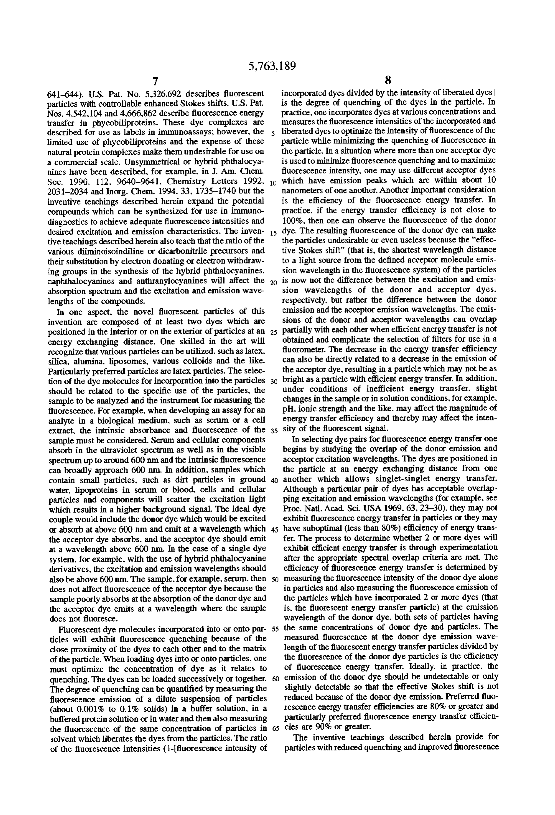
intensities. A large majority of fluorescent molecules have Si(CH)CF5 aromatic character, that is, they possess 4n+2 pi electrons. Si(CH3)3
The resultant aromatic character promotes stacking of the molecules, especially of water insoluble molecules in aque Si(CH)(CH)CN ous solutions or in particles in aqueous solution, which in Si(CH)(CH)COOCH turn promotes fluorescence quenching. The novel fluores cent particles described in the instant invention are incor Si(CH)CH=CH porated with dyes which, through steric interference of the Si(CH)(CH2)COOH dye molecules, have a minimized propensity to stack in the particles. In another aspect of this invention, fluorescence O Si(CH)(CH2)Cl; and quenching of dye molecules in particles is minimized by Si(CH3)(CH)CH=CH.
employing different dyes with approximately the same exci The parent compounds of the phthalocyanines and naphtha tation and emission wavelengths. That is, the wavelength maximum for excitation and/or emission of the different locyanines are preferred because their emission wavelengths dyes are within about 10 nm of each other so that there is 15 are around 680 nm and 780 nm in latex particles, respec substantial overlap of the peaks. One skilled in the art can tively. Also preferred parent compounds are the anthrany appreciate that the width of excitation and emission spectra locyanines which have emissions around 850 to 900 nm. of various dyes can vary. The principle here is that different These three classes of parent compounds will collectively be dyes will not stack in an organized orientation with each other to the same degree as dyes which are the same. An called "phthalocyanine derivatives" and may or may not analogy to this stacking principle is the depression of the 20 have an included metal and may or may not have axial melting point of a pure compound by an impurity. It is well ligands. The emission wavelengths for the phthalocyanine known to physical chemists that an impurity in a solid derivatives are particularly useful for quantifying fluores compound lowers its melting point because the impurity cence in biological samples and for minimizing the back disrupts the formation of the crystal lattice of the pure ground scatter intensity. Those skilled in the art can appre compound. Incorporating dyes into or onto particles using 25 organic solvents and then removing the solvent causes the ciate that phthalocyanine derivatives can be synthesized, for dye to precipitate or crystallize in the particle. The disrup example, by derivatization of the phenyl. naphthyl or anthra tion of the crystalline lattice of dye molecules in particles nyl rings with various substitutes to yield different mol will alter the stacking of the molecules and thereby reduce ecules but these variants, also are within the scope of the quenching. Thus, incorporation of dissimilar dye molecules 30 instant invention. Derivatives of tetraazaporphine are also with similar excitation and emission spectra improves fluo within the scope of the instant invention. The derivatization rescence intensities of the particles by decreasing the of the aromatic structure can produce blue or red shifted quenching interactions of the molecules. excitation or emission wavelengths. The choice of the donor In another aspect of this invention, incorporation into dye to excite the phthalocyanine derivative dyes is depen particles of dissimilar dyes which exhibit fluorescence 35 dent on having a donor dye emission wavelength which energy transfer in the particles may also disrupt the other's crystalline lattice formation. Thus, the fluorescence intensi corresponds lengths of to the appropriate range of absorbance wave the phthalocyanine derivative. FIG. 3 shows the ties of particles exhibiting fluorescence energy transfer will absorbance spectra of the silicon dihydroxyphthalocyanine be improved as a result of decreasing quenching in the particle because the stacking of similar dyes in the particles and silicon dihydroxynaphthalocyanine in dimethylforma is disrupted by the dissimilar dye. mide. A potential range of excitation of the these acceptor In yet another aspect of this invention, the synthesis of dyes by the donor dye is between approximately 550 nm and phthalocyanine derivatives and hybrid phthalocyanine 670 nm and 600 nm and 760 nm, respectively. One skilled derivatives with axial ligands reduces the stacking of the in the art will recognize that many dyes would be candidates aromatic ring System, thus minimizing the interactions 45 for the donor dye because of the wide useful range of between molecules and maximizing fluorescence intensities. wavelengths which can excite the acceptor dyes. The choice One skilled in the art can appreciate that more than one of the acceptor dye should meet the criteria outlined above. dye pair which exhibits fluorescence energy transfer can be Several examples are described which illustrate the versa incorporated into or onto particles resulting in a class of tility of this novel approach. Assume that an instrument is to particles which fluoresce at different wavelengths. In 50 be built with an excitation source which has a maximum addition, with the inventive teachings described herein, intensity at 480 nm and a detector which has a good quantum incorporation into or onto particles of 3 or more dyes, which together provide a cascade of energy transfer from the efficiency at 600 to 700 nm. The donor dye should thus be absorber to the intermediate donor to the acceptor (which capable of being excited at 480 nm and further assuming that fluoresces), can result in the production of particles with 55 a phthalocyanine derivative is the acceptor dye for emission very long Stokes shifts and allows one to produce particles at 680 nm, the donor should then emit in the range of 550 with nearly an unlimited variety of excitation and emission to 670 nm.
characteristics.
FIG. 1 shows preferred acceptor dyes which are phenylbutadienylPreferred classes of dyes for this application are styryl, phthalocyanines, naphthalocyanines and anthranylocya are those of the following and phenylhexatrienyl dyes. Styryl dyes nines. FIG. 2 shows particularly preferred acceptor dyes formula: which are derivatives of silicon phthalocyanines, naphtha locyanines and anthranylocyanines, where R is hydrogen or *: an alkylcarbon chain from 1-20 carbons, either saturated or unsaturated, having 0-10 heteroatoms (N.O.S.), and having 65 0 or 1 siloxide groups. The best mode compounds are those in which R=
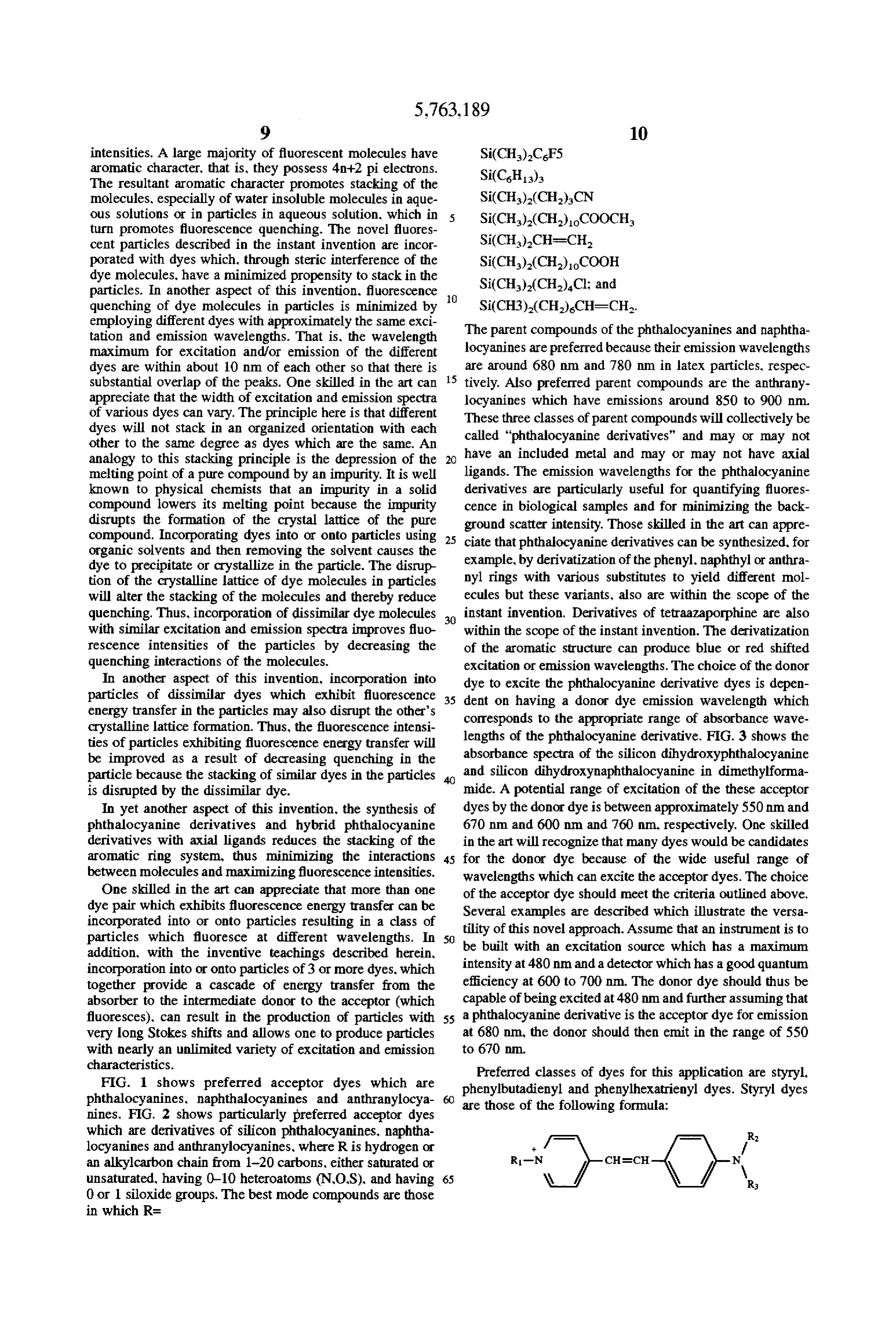
Page 15
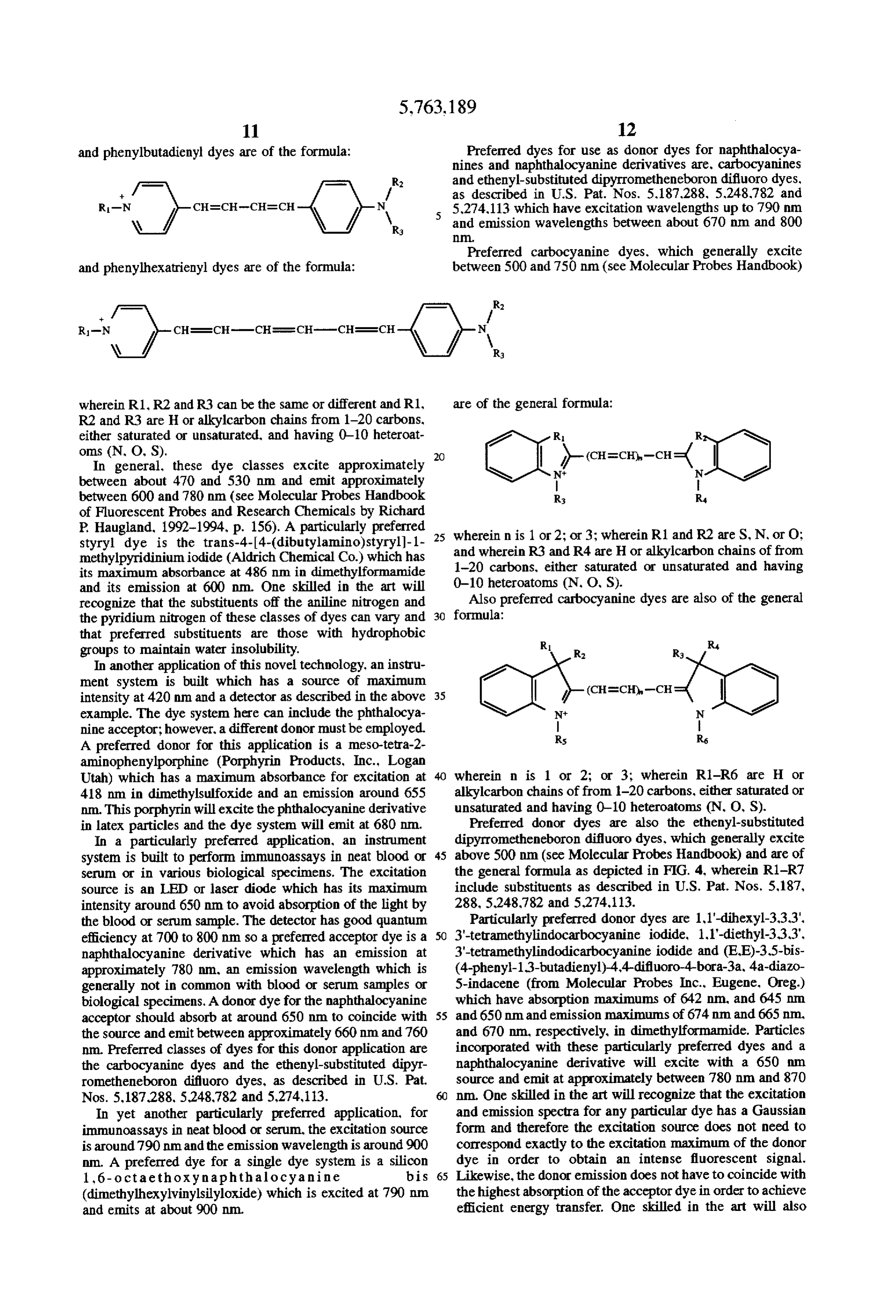
and phenylbutadienyl dyes are of the formula: Preferred dyes for use as donor dyes for naphthalocya nines and naphthalocyanine derivatives are, carbocyanines - . and ethenyl-substituted dipyrrometheneboron difluoro dyes.
C 'e, N 5,274,113 which have excitation wavelengths up to 790 nm and emission wavelengths between about 670 nm and 800
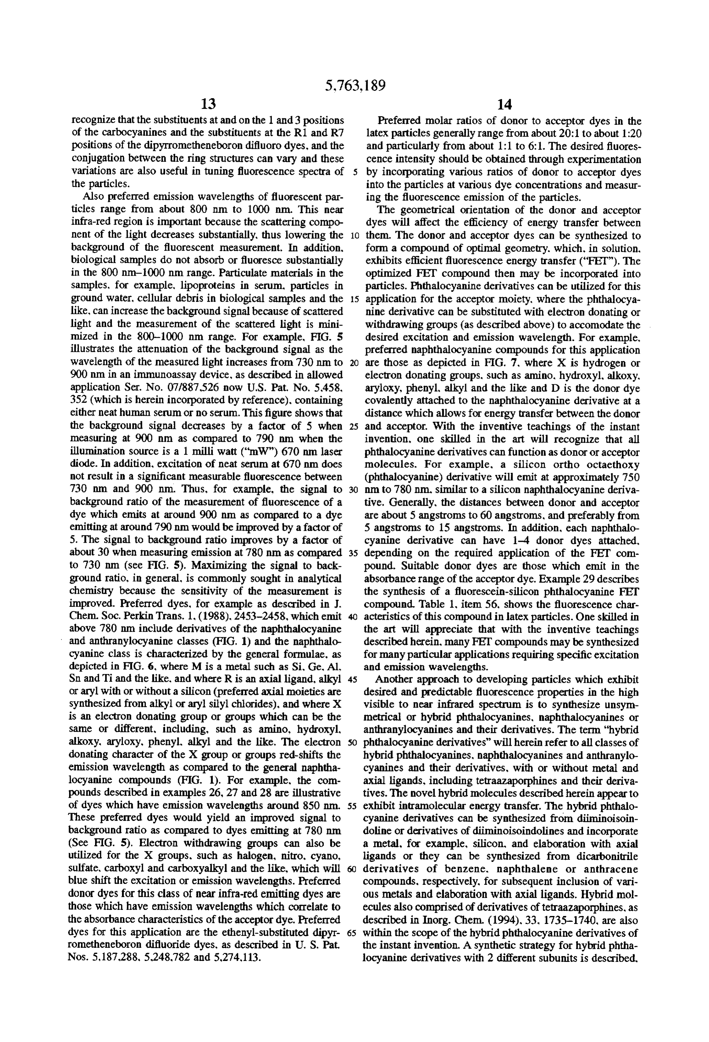
Preferred carbocyanine dyes, which generally excite and phenylhexatrienyl dyes are of the formula: between 500 and 750 nm (see Molecular Probes Handbook)
a / W
wherein R1,R2 and R3 can be the same or different and R1, are of the general formula:
R2 and R3 are H or alkylcarbon chains from 1-20 carbons, either saturated or unsaturated, and having 0-10 heteroat R R
In general, these dye classes excite approximately between about 470 and 530 nm and emit approximately
between 600 and 780 nm (see Molecular Probes Handbook R3 R of Fluorescent Probes and Research Chemicals by Richard
P. Haugland, 1992-1994, p. 156). A particularly preferred 25 wherein n is 1 or 2; or 3; wherein R1 and R2 are S, N, or O: styryl dye is the trans-4-4-(dibutylamino) styryl)-1- methylpyridinium iodide (Aldrich Chemical Co.) which has and wherein R3 and R4 are H or alkylcarbon chains of from its maximum absorbance at 486 nm in dimethylformamide 1-20 carbons, either saturated or unsaturated and having and its emission at 600 nm. One skilled in the art will 0-10 heteroatoms (N, O, S).
Also preferred carbocyanine dyes are also of the general recognize that the substituents off the aniline nitrogen and formula:
the pyridium nitrogen of these classes of dyes can vary and 30 that preferred substituents are those with hydrophobic groups to maintain water insolubility. R1 R R3 R In another application of this novel technology, an instru ment system is built which has a source of maximum intensity at 420 nm and a detector as described in the above 35 example. The dye system here can include the phthalocya nine acceptor; however, a different donor must be employed. R5 Rs A preferred donor for this application is a meso-tetra-2- aminophenylporphine (Porphyrin Products, Inc., Logan
Utah) which has a maximum absorbance for excitation at wherein n is 1 or 2; or 3; wherein R1-R6 are H or 418 nm in dimethylsulfoxide and an emission around 655 alkylcarbon chains of from 1-20 carbons, either saturated or nm. This porphyrin will excite the phthalocyanine derivative unsaturated and having 0-10 heteroatoms (N, O, S). in latex particles and the dye system will emit at 680 nm. Preferred donor dyes are also the ethenyl-substituted In a particularly preferred application, an instrument dipyrrometheneboron difluoro dyes, which generally excite system is built to perform immunoassays in neat blood or 45 above 500 nm (see Molecular Probes Handbook) and are of serum or in various biological specimens. The excitation the general formula as depicted in FIG. 4, wherein R1-R7 source is an LED or laser diode which has its maximum include substituents as described in U.S. Pat. Nos. 5,187, intensity around 650 nm to avoid absorption of the light by 288, 5.248,782 and 5,274,113.
the blood or serum sample. The detector has good quantum Particularly preferred donor dyes are 1, 1'-dihexyl-3,3,3'. efficiency at 700 to 800 nm so a preferred acceptor dye is a 50 3'-tetramethylindocarbocyanine iodide, 1.1'-diethyl-3,3,3'. naphthalocyanine derivative which has an emission at 3'-tetramethylindodicarbocyanine iodide and (E.E)-3,5-bis approximately 780 nm, an emission wavelength which is (4-phenyl-1,3-butadienyl)-4,4-difluoro-4-bora-3a, 4-a-diazo generally not in common with blood or serum samples or 5-indacene (from Molecular Probes Inc., Eugene, Oreg.) biological specimens. A donor dye for the naphthalocyanine which have absorption maximums of 642 nm, and 645 nm. acceptor should absorb at around 650 nm to coincide with 55 and 650 nm and emission maximums of 674 nm and 665 nm, the source and emit between approximately 660 nm and 760 and 670 nm, respectively, in dimethylformamide. Particles nm. Preferred classes of dyes for this donor application are incorporated with these particularly preferred dyes and a the carbocyanine dyes and the ethenyl-substituted dipyr naphthalocyanine derivative will excite with a 650 mm rometheneboron difluoro dyes, as described in U.S. Pat. source and emit at approximately between 780 nm and 870 Nos. 5,187,288, 5.248,782 and 5,274,113. nm. One skilled in the art will recognize that the excitation In yet another particularly preferred application, for and emission spectra for any particular dye has a Gaussian immunoassays in neat blood or serum, the excitation source form and therefore the excitation source does not need to is around 790 nm and the emission wavelength is around 900 correspond exactly to the excitation maximum of the donor nm. A preferred dye for a single dye system is a silicon dye in order to obtain an intense fluorescent signal. 1,6- octaethoxynaphthalocyanine bis 65 Likewise, the donor emission does not have to coincide with (dimethylhexylvinylsilyloxide) which is excited at 790 nm. the highestabsorption of the acceptor dye in order to achieve and emits at about 900 nm. efficient energy transfer. One skilled in the art will also
Page 16
recognize that the substituents at and on the 1 and 3 positions Preferred molar ratios of donor to acceptor dyes in the of the carbocyanines and the substituents at the R1 and R7 latex particles generally range from about 20:1 to about 1:20 positions of the dipyrrometheneboron difluoro dyes, and the and particularly from about 1:1 to 6:1. The desired fluores conjugation between the ring structures can vary and these cence intensity should be obtained through experimentation variations are also useful in tuning fluorescence spectra of 5 by incorporating various ratios of donor to acceptor dyes the particles. into the particles at various dye concentrations and measur Also preferred emission wavelengths of fluorescent par ing the fluorescence emission of the particles. ticles range from about 800 nm to 1000 nm. This near The geometrical orientation of the donor and acceptor infra-red region is important because the scattering compo dyes will affect the efficiency of energy transfer between nent of the light decreases substantially, thus lowering the 10 them. The donor and acceptor dyes can be synthesized to background of the fluorescent measurement. In addition, form a compound of optimal geometry, which, in solution, biological samples do not absorb or fluoresce substantially exhibits efficient fluorescence energy transfer ("FET"). The in the 800 nm-1000 nm range. Particulate materials in the optimized FET compound then may be incorporated into samples, for example, lipoproteins in serum, particles in particles. Phthalocyanine derivatives can be utilized for this ground water, cellular debris in biological samples and the 15 application for the acceptor moiety, where the phthalocya like, can increase the background signal because of scattered nine derivative can be substituted with electron donating or light and the measurement of the scattered light is mini withdrawing groups (as described above) to accomodate the mized in the 800-1000 nm range. For example, FIG. 5 desired excitation and emission wavelength. For example, illustrates the attenuation of the background signal as the preferred naphthalocyanine compounds for this application wavelength of the measured light increases from 730 nm to 20 are those as depicted in FIG. 7, where X is hydrogen or 900 nm in an immunoassay device, as described in allowed electron donating groups, such as amino, hydroxyl, alkoxy. application Ser. No. 07/887,526 now U.S. Pat. No. 5.458, aryloxy, phenyl, alkyl and the like and D is the donor dye 352 (which is herein incorporated by reference), containing covalently attached to the naphthalocyanine derivative at a either neat human serum or no serum. This figure shows that distance which allows for energy transfer between the donor the background signal decreases by a factor of 5 when 25 and acceptor. With the inventive teachings of the instant measuring at 900 nm as compared to 790 nm when the invention, one skilled in the art will recognize that all illumination source is a 1 milli watt (“mW") 670 nm laser phthalocyanine derivatives can function as donor or acceptor diode. In addition, excitation of neat serum at 670 nm does molecules. For example, a silicon ortho octaethoxy not result in a significant measurable fluorescence between (phthalocyanine) derivative will emit at approximately 750 730 nm and 900 nm. Thus, for example, the signal to 30 nm to 780 nm, similar to a silicon naphthalocyanine deriva background ratio of the measurement of fluorescence of a tive. Generally, the distances between donor and acceptor dye which emits at around 900 nm as compared to a dye are about 5 angstroms to 60 angstroms, and preferably from emitting at around 790 nm would be improved by a factor of 5 angstroms to 15 angstroms. In addition, each naphthalo 5. The signal to background ratio improves by a factor of cyanine derivative can have 1-4 donor dyes attached, about 30 when measuring emission at 780 nm as compared 35 depending on the required application of the FET com to 730 nm (see FIG. 5). Maximizing the signal to back pound. Suitable donor dyes are those which emit in the ground ratio, in general, is commonly sought in analytical absorbance range of the acceptor dye. Example 29 describes chemistry because the sensitivity of the measurement is the synthesis of a fluorescein-silicon phthalocyanine FET improved. Preferred dyes, for example as described in J. compound. Table 1, item 56, shows the fluorescence char Chem. Soc. Perkin Trans. 1. (1988), 2453-2458, which emit acteristics of this compound in latex particles. One skilled in above 780 nm include derivatives of the naphthalocyanine the art will appreciate that with the inventive teachings and anthranylocyanine classes (FIG. 1) and the naphthalo described herein, many FET compounds may be synthesized cyanine class is characterized by the general formulae, as for many particular applications requiring specific excitation depicted in FIG. 6, where M is a metal such as Si, Ge. Al, and emission wavelengths.
Sn and Ti and the like, and where R is an axial ligand, alkyl 45 Another approach to developing particles which exhibit or aryl with or without a silicon (preferred axial moieties are desired and predictable fluorescence properties in the high synthesized from alkyl or aryl silyl chlorides), and where X visible to near infrared spectrum is to synthesize unsym is an electron donating group or groups which can be the metrical or hybrid phthalocyanines, naphthalocyanines or same or different, including, such as amino, hydroxyl, anthranylocyanines and their derivatives. The term "hybrid alkoxy, aryloxy, phenyl alkyl and the like. The electron SO phthalocyanine derivatives” will herein refer to all classes of donating character of the X group or groups red-shifts the hybrid phthalocyanines, naphthalocyanines and anthranylo emission wavelength as compared to the general naphtha cyanines and their derivatives, with or without metal and locyanine compounds (FIG. 1). For example, the com axial ligands, including tetraazaporphines and their deriva pounds described in examples 26, 27 and 28 are illustrative tives. The novel hybrid molecules described herein appear to of dyes which have emission wavelengths around 850 nm. 55 exhibit intramolecular energy transfer. The hybrid phthalo These preferred dyes would yield an improved signal to cyanine derivatives can be synthesized from diiminoisoin background ratio as compared to dyes emitting at 780 nm. doline or derivatives of diminoisoindolines and incorporate (See FIG. 5). Electron withdrawing groups can also be a metal, for example, silicon, and elaboration with axial utilized for the X groups, such as halogen, nitro. cyano, ligands or they can be synthesized from dicarbonitrile sulfate, carboxyl and carboxyalkyl and the like, which will derivatives of benzene, naphthalene or anthracene blue shift the excitation or emission wavelengths. Preferred compounds, respectively, for subsequent inclusion of vari donor dyes for this class of near infra-red emitting dyes are ous metals and elaboration with axial ligands. Hybrid mol those which have emission wavelengths which correlate to ecules also comprised of derivatives of tetraazaporphines, as the absorbance characteristics of the acceptor dye. Preferred described in Inorg. Chem. (1994), 33. 1735-1740, are also dyes for this application are the ethenyl-substituted dipyr 65 within the scope of the hybrid phthalocyanine derivatives of rometheneboron difluoride dyes, as described in U. S. Pat. the instant invention. A synthetic strategy for hybrid phtha Nos. 5,187,288, 5.248,782 and 5,274,113. locyanine derivatives with 2 different subunits is described,
Page 17
for example. in J. Am. Chem. Soc. (1990), 112, 9640-9641, carboxylic acid or amino substituents which can affect Inorg. Chem. (1994).33. 1735-1740, Chem. Letters, (1992). solubility of the molecule. When using the dicarbonitrile 763-766. Chem. Letters. (1992), 1567-1570 and Chem. precursors, the phthalocyanine derivative is synthesized Letters, (1992). 2031-2034. These papers refer to the syn without metal, but various metals can subsequently be thesis of hybrid molecules with zinc metal or without metal included, for example, Ge. Al, Sn, Ti and the like. These and without axial ligands. The versatility of the synthetic metals can also be elaborated with axial ligands, depending approach described herein as it applies to the inventive on the valence of the metal.
teachings of the instant invention is that the character of the The fluorescence quenching character of the hybrid phtha diminoisoindoline and its derivatives will dictate the exci locyanine derivatives are particularly preferred over the tation and emission characteristics of the molecule and, 10 phthalocyanine derivatives. Example 32 is atypical example furthermore, elaboration with axial ligands will minimize of comparison of the quenching characteristics in latex quenching by decreasing stacking in the particles and maxi particles of silicon 2,3-naphthalocyanine bis mize fluorescence intensity, Axial ligands on hybrid phtha (dimethylhexylvinylsilyloxide) and silicon di(1,6- locyanine derivatives are also beneficial on water soluble diphenylnaphthalocyanine) diphthalocyanine bis compounds because the axial ligands will minimize inter 15 (dimethylhexylvinylsilyloxide). The hybrid phthalocyanine action of the hybrid molecule with, for example, proteins, derivative has essentially no quenching as compared to up to antibodies and nucleic acids, which may or may not be 50% quenching of the naphthalocyanine derivative for the covalently coupled to the hybrid molecule. various dye loading concentrations listed in the table. The Novel hybrid phthalocyanine derivatives are described fluorescence intensities of latex containing the hybrid phtha herein, which contain 3 or 4 different subunits, and allow for 20 locyanine derivative are much greater than the phthalocya larger Stokes shifts. The principle is that excitation occurs nine derivative. This illustrates the special properties of the with the subunit which has the highest energy or the lowest hybrid phthalocyanine derivatives.
wavelength absorption and the emission occurs in the lowest The tetramerization reactions of the diminoisoindoline or energy subunit. dicarbonitrile precursors to form the hybrid phthalocyanine The desired excitation and emission wavelengths of the 25 derivatives can be directed so that opposing subunits can be hybrid phthalocyanine derivative will determine the types of the same. This is accomplished, for example, with the use of diminoisoindoline derivative and dicarbonitrile derivative bulky substituents on the precursors so that in the tetramer precursors which are used in the synthesis of the hybrid ization reaction, like subunits with bulky substituents cannot phthalocyanines. The desired excitation and emission wave be adjacent because of steric considerations. Bulky phenyl lengths are generally dictated by the sample, the type of 30 substituents have been used on dicarbonitrile precursors to fluorescent measurement and the instrument. Various com direct the precursors tetramerization to be opposing subunits binations of diiminoisoindoline derivative and dicarbonitrile as described in Inorg. Chem. (1994),33, 1735-1740, Chem derivative precursors may also combine to form a hybrid istry Letters (1992). 2031-2034 and Chemistry Letters phthalocyanine derivative which may have a red shifted or (1992), 1567-1570. These references, however, do not blue shifted excitation and/or emission wavelength pattern. 35 describe the synthesis of the novel phthalocyanine deriva In general, electron donating substituents on the dimi tives described herein using diminoisoindoline precursors noisoindoline or dicarbonitrile precursors, particularly situ with or without axial ligands.
ated at the orthopositions (that is, ortho to the tetraazapor Preferred hybrid phthalocyanine derivatives have similar phine structure as indicated in FIG. 6 for the X substituents) opposing subunits so that two different subunits comprise of the phthalocyanine structure, such as amino, hydroxyl, the structure. Particularly preferred hybrid phthalocyanine alkoxy, aryloxy, phenyl, alkyl and the like, will red shift the derivatives have similar opposing subunits on one axis and excitation and/or emission wavelengths. Conversely. different opposing subunits on the other axis. The nature of generally, electron withdrawing substituents, also particu the particularly preferred molecules is that red or blue larly at the ortho positions, such as halogen, nitro, cyano, shifted excitation or emission wavelengths and a longer sulfate, carboxyl and carboxyalkyl and the like, will blue 45 Stokes shift can result because of the selection of the shift the excitation or emission wavelengths. In addition, precursor molecules for the tetramerization reaction. For positions on the subunits other than the ortho positions can particularly preferred hybrid phthalocyanine derivatives, for affect the excitation and emission characteristics of the example, the "donor” diphenyldiiminoisoindoline or the hybrid phthalocyanine derivative. The choice of either diiminoisoindoline precursors would contribute to 650 nm diiminoisoindoline or dicarbonitrile precursors for the syn 50 absorbance of the hybrid molecule, and thereby to the thesis of the hybrid phthalocyanine derivatives is generally excitation of the hybrid molecule. The diphenyl phenyldi related to the desired presence or absence of metal and the iminoisoindoline or the phenyldiiminoisoindoline precur type of metal in the hybrid molecule. For example, when sors would act as an "electron transfer subunit" to the using the diiminoisoindoline precursors in the synthesis, a "acceptor subunit", which would be a dialkoxy or aryloxy silicon metal can be incorporated during the tetramerization 55 phenyldiiminoisoindoline precursors, so that emission is reaction to form the phthalocyanine derivative structure. The dictated at the lowest energy by the acceptor subunit at about silicon can be further modified to a silicon dihydroxy 850 nm. The nature of the "electron transfer subunit" is phthalocyanine derivative molecule so that axial ligands can important because it is not desirable for this subunit to emit be elaborated with, for example, various silyl chloride because then the desired emission of the acceptor subunit reagents. The importance of axial ligands in reducing will not take place. Thus, the HOMO and LUMO character quenching and maximizing fluorescence intensity is evident of the electron transfer subunit should be designed with for both phthalocyanine/naphthalocyanine molecules and reference to the donor and acceptor subunit molecules. The the hybrid phthalocyanine derivatives (see example 31). The relationship of the energies of the HOMO and LUMO as axial ligands can also be useful for further elaboration of the they relate to excitation and emission are taught by Pariser molecules, for example, for attaching another fluorescent 65 et al., J. Chem. Phys. (1953), 21. 767-776, by Pople. Trans. molecule, for attaching to a protein, polypeptide or nucleic Faraday Soc. (1953), 49, 1375-1385, by McHugh et al. acid or for changing the charge of the molecule using sulfate. Theoret. Chim. Acta (Berlin) (1972). 24, 346-370 and by
Page 18
Kobayashi et al., Inorg. Chem. (1994).33, 1735-1740. are required for a specific purpose. The adsorption of Chemistry Letters (1992). 2031-2041, Konami et al., macromolecules to particles, particularly latex particles is Molecular Physics (1993), 80, 153-160. well known to those skilled in the art and generally involves Another application requires the hybrid molecule to have adsorption of the macromolecule at a temperature between two excitation wavelengths, one at approximately 650 nm. 5 5° C. and 50° C. and at a pH which is below the pI of the and another at about 680 nm with emission for both exci molecule. For example, fluorescent particles exhibiting fluo tations at about 760 nm. Thus, the precursors responsible for rescence energy transfer can be adsorbed with either anti the excitation could be a diminoisoindoline for the 650 nm. bodies for use in non-competitive immunoassays or ligand and a tetrafluorodiiminoisoindoline for the 680 nm excita analogues for use in competitive immunoassays in reaction tions. The emitting subunit, which can also be used to direct O mixtures of the assays. In the case of non-competitive the tetramerization reaction so that the emitting subunits are assays, the reaction mixture would include at least one target opposed in the molecule, can be a diphenyl phenyldiimi ligand and at least one class of fluorescent particles having noisoindoline. The excitation and emission wavelengths of bound thereto at least one receptor specific for target ligand, the resulting hybrid phthalocyanine derivative are thus gen forming an antibody (fluorescent) conjugate. In the case of erally representitive of the individual diminoisoindoline 15 competitive assays, the reaction mixture will include at least precursors. one target ligand, at least one receptor specific to the target Yet another application requires excitation at about 650 ligand, and at least one class of fluorescent particles, having nm and emission at about 750 nm. The precursors respon bound thereto at least one ligand analogue, forming a ligand sible for excitation and emission could be diminoisoindo analogue (fluorescent) conjugate. The antibody conjugates line and diphenyl phenyldiiminoisoindoline, respectively. bound to target ligands in the non-competitive reaction The latter precursor also acts to direct the emitting subunits mixture and the ligand analogue conjugates not bound by to be opposed. receptors specific to the target ligands in the competitive In another application, a large extinction coefficient at the reaction mixture can be bound to a solid phase consisting of excitation wavelength is desired for excitation at about 650 receptors specific to another epitope of the target ligand of nm. The emission wavelength should be at about 850 nm. 25 the target ligand-antibody conjugate complexes and of The precursors responsible for excitation could be a receptors specific to ligand analogues of the ligand analogue diphenyldiiminoisoindoline, which would direct these sub conjugates, respectively. The fluorescent conjugates units to be opposed and thereby two subunits would con unbound by the solid phase are removed and the fluores tribute to provide the desired extinction coefficient. A phe cence of the bound conjugates is measured. The measured nyldiiminoisoindoline derivative precursor could act as an 30 fluorescence is related to the target ligand concentration. The electron transfer subunit and an alkoxy phenyldiiminoisoin various reagents described above can also be attached doline precursor could be the acceptor with a characteristic covalently to the latex particles. For example, antibodies or emission at about 850 nm. ligand analogues can be attached through amine or carboxy In another application, two emission wavelengths are lic acids to carboxylic acids or amines on the surface of the desired from a compound which is excited at a single 35 particles, respectively, to form stable amide linkages. wavelength. The desired excitation is around 650 nm and the In the case of quantifying nucleic acids in samples, the emission should be around 760 nm and 810 mm. The novel compounds described in the instant invention are precursor responsible for excitation could be a tetrafluoro useful because of their brightness and because of the near diiminois oindoline or a tetrafluorobenzene-1,2- infrared emission characteristics. In general, in designing an dicarbonitrile. The precursor responsible for emission could assay for a nucleic acid, one selects a probe molecule which be a dibutoxyphenyldiiminoisoindoline or a 34-dibutoxy is complementary to the nucleic acid to be quantified. The naphthalene-1,2-dicarbonitrile, respectively. probe molecule is then labeled, generally covalently, with a The resulting compounds are then incorporated into par signal generator. The signal generator can be a water soluble ticles to yield particles which exhibit excitation wavelengths phthalocyanine derivative or hybrid phthalocyanine deriva above about 600 nm and emission wavelengths above about 45 tive or aparticle with the appropriate dye system, which may 650 nm. One skilled in the art will also appreciate that water exhibit fluorescence energy transfer or hybrid phthalocya soluble hybrid phthalocyanine derivatives are valuable for nine derivatives or combinations of these compounds. The coupling to proteins, polypeptides, nucleosides, nucleic labelled probe molecule is then introduced into a biological acids and the like, for detecting their presence in biological sample suspected of containing the target nucleic acid, and fluids or for performing DNA probe or immunoassays. 50 the labelled probe sequence assembles with the target Preferred particle sizes range from about 0.1 nm to 5000 nucleic acid. The labelled probe/target nucleic acid can then nm and preferably from about 1 nm to 1000 nm. The choice be immobilized onto a surface which has immobilized of particle size should be related to the specific function for another nucleic acid which is also complementary to the the label. The particle size may vary for a particular appli target nucleic acid. Conversely, the biological sample can be cation. For example, in an immunoassay, if the label requires 55 introduced to a surface which has immobilized a comple a more intense fluorescence for measuring very low con mentary nucleic acid for immobilization of the target nucleic centrations of analytes, then one would employ larger par acid. The labelled probe can then beintroduced to the system ticles because larger particles can incorporate more dye for binding to the immobilized target molecule. The excess molecules. The small particle sizes (0.1-1 nm) may be labelled probe is then washed away and the resultant fluo employed in fluorescence polarization assays, as described rescent intensity is correlated with fluorescence intensity for example, in U.S. Pat. Nos. 4.420,568, 4.476229 and from a standard curve to arrive at a concentration of the 4.510,251, in in vitro visualization of cellular components or nucleic acid in the sample.
in in vivo imaging techniques. Those skilled in the art will recognize that many varia The resulting fluorescent dye particles which exhibit the tions of immunoassays and nucleic acid assays can be appropriate excitation and emission characteristics are fur 65 performed and the inventive teachings in the instant inven ther adsorbed or chemically reacted with various nucleic tion for the use of novel dye systems can be used to develop acids, nucleotides, proteins or peptides and the like which novel adaptations to existing technologies.
Page 19
Those skilled in the art will appreciate that the novel added chlorodimethylvinylsilane (276 L, 2.0 mmol) and fluorescent particles described herein have many uses in the mixture was refluxed with stirring on an oil bath at 130° immunoassays, fluorescence microscopy, in vivo imaging, C. for 5 hours. The dark solution was allowed to cool and in vitro cancer therapy, nucleic acid assays, cell sorters and was evaporated. The residue was purified on a Silica gel 60 the like. A column equilibrated in hexane and the product was eluted Experimental Section with toluene as a blue band. The eluate containing product Fluorescence measurements were performed on a Perkin was evaporated, the residue treated with hexane and the dark Elmer model LS 50B Luminescence Spectrometer for dyes blue solid product was filtered, washed with hexane and was emitting up to around 780 nm. In some instances, dyes dried under vacuum to afford 7.5 mg of the title compound. emitting above 800 nm were measured according to 10
Example 18. The fluorescence intensities are not corrected. EXAMPLE 5 Absorbance measurements were performed on a Hewlett
Packard 8452A Diode Array Spectrophotometer. Synthesis of Silicon Phthalocyanine bis(3- EXAMPLE 1. cyanopropyl) dimethylsilyloxide) (Hereinafter
Synthesis of Silicon Phthalocyanine Dihydroxide 15 sometimes referred to as PCSi cyano) SiPc(OH) To a suspension of silicon phthalocyanine dihydroxide A suspension of silicon phthalocyanine dichloride (1.83g. (115 mg 0.2 mmol) in anhydrous pyridine (11 mL) was 3.0 mmol) in pyridine (50 mL) and water (50 mL) was added chloro(3-cyanopropyl)-dimethylsilane (328 ul. 2.0 refluxed with stirring on an oil bath at 120° C. for 18 hours. mmol) and the mixture was refluxed with stirring on an oil After cooling the dark blue solid product was filtered and the bath at 130° C. for 5 hours. The purple solution was allowed residue was washed with water (10 mL), acetone (5 mL) and to cool and was evaporated. The residue was purified on a then dried under vacuum to afford 1.71 g of the title Silica gel 60 A column equilibrated in hexane. The column compound. was washed with toluene and the product was eluted with EXAMPLE 2 toluenefisopropyl alcohol (90/10, viv) as a bright blue band. 25 The eluate containing product was evaporated under vacuum
Synthesis of Silicon Phthalocyanine bis to afford 101 mg of the title compound with amp>260° C. (trihexylsilyloxide) (hereinafter sometimes referred to as PCSi trihexyl) EXAMPLE 6
A suspension of silicon phthalocyanine dihydroxide (115 mg 0.2 mmol) in anhydrous pyridine (11 mL) containing 30 Synthesis of Silicon Phthalocyanine bis chlorotrihexylsilane (733 ul. 2.0 mmol) was refluxed on an (dimethylpentafluoro-phenylsilyloxide) (Hereinafter oil bath at 130° C. for 5 hours. The resulting purple solution sometimes referred to as PoSi pentafluoro) was allowed to cool and was evaporated. The resulting To a suspension of silicon phthalocyanine dihydroxide slurry was treated with ice-cold hexane (2 mL) and the dark blue solid product was filtered, washed with ice-cold hexane 35 (115 mg 0.2 mmol) in anhydrous pyridine (11 mL) was (2 mL) and was dried under vacuum to yield 249 mg of added chlorodimethylpentafluorophenylsilane (376 ul. 2.0 crude product. The crude product in chloroform was purified mmol) and the mixture was refluxed with stirring on an oil on an Alumina column (Activity 1) equilibrated in hexane bath at 130° C. for 5 hours. The dark green solution was and the product was eluted with hexane/toluene (2/1, vi?v) as allowed to cool and was evaporated. The residue was a bright blue band. The solvent containing the product was purified on a Silica gel 60 A column equilibrated in hexane. evaporated to yield 69 mg of the title compound with a mp The product was eluted with toluene as a dark blue band. 171° C. (lit mp 175° C). The eluate containing the product was evaporated, the EXAMPLE 3 residue was treated with hexane (10 mL) and the dark blue solid product was filtered, washed with hexane and was
Synthesis of Silicon Phthalocyanine bis(10 45 dried under vacuum to afford 73 mg of the title compound. carbomethoxydecyl) dimethylsilyloxide)
(Hereinafter sometimes referred to as PCSi methyl EXAMPLE 7 ester) Synthesis of Silicon 2.3-Naphthalocyanine
To a suspension of silicon phthalocyanine dihydroxide Dihydroxide (Hereinafter sometimes referred to as (115 mg 0.2 mmol) in anhydrous pyridine (11 mL) was 50 NaPcSi hydroxide) added (10-carbomethoxydecyl)dimethylchlorosilane (586 mg, 2 mmol) and the mixture was refluxed with stirring on A suspension of silicon 2.3-naphthalocyanine dichloride an oil bath at 130° C. for 5 hours. The dark blue solution was (280 mg 0.34 mmol) in pyridine (10 mL) and water (10 mL) allowed to cool and the solvent was evaporated. The residue was refluxed with stirring on an oil bath at 130° C. for 24 was purified on a Silica gel 60 A column equilibrated in 55 hours. After cooling to room temperature, the dark green hexane and the product eluted slowly as a blue band with solid product was filtered and, the residue was washed, toluene. The toluene fraction containing product was successively, with water (5 mL) and acetone (2 mL). The evaporated, hexane (10 mL) was added to the residue and product was dried under vacuum to afford 217 mg of the title the blue product was filtered, washed with hexane and dried compound.
to afford 105 mg of the title compound.
EXAMPLE 8
EXAMPLE 4
Synthesis of Silicon Phthalocyanine bis Synthesis of Silicon 2.3-Naphthalocyanine bis (dimethylvinylsilyloxide) (Hereinafter sometimes (dimethylvinylsilyloxide) (Hereinafter sometimes referred to as PeSi vinyl) 65 referred to as NaPcSi vinyl)
To a suspension of silicon phthalocyanine dihydroxide To a suspension of silicon 2.3-naphthalocyanine dihy (115 mg 0.2 mmol) in anhydrous pyridine (11 mL) was droxide (87 mg. 0.11 mmol) in anhydrous dimethylforma
Page 20
mide (1 mL) was added chlorodimethylvinylsilane (0.042 30 minutes to swell the latex. The dye solution (0.04 mL), mL, 0.3 mmol). followed by imidazole (14 mg. 0.2 mmol). which consists of one or more dyes at an appropriate The mixture was stirred under argon at room temperature for concentration in tetrahydrofuran, was added dropwise over 24 hours. The solvent was evaporated and the residue was 5 minutes to the stirred latex solution, to give the loading dye purified on a Silica gel 60 A column which was equilibrated 5 concentration (in 2 mL volume) as indicated in Table 1. The in hexane. The product was eluted with toluene as a green latex-dye solution was stirred at room temperature for 30 band. The toluene fraction containing the product was minutes in the dark. The latex solution was then transferred evaporated and the residue was treated with hexane. The to dialysis tubing (Spectra-por, 12-14,000 molecular weight dark green solid was filtered, washed with hexane and was cutoff. Spectrum, Houston. Tex.) and the dye-latex solutions dried under vacuum to afford 26 mg of the title compound. 10 were dialyzed against water for 12 to 15 hours at 4°C. The EXAMPLE 9 dye-latex solutions were removed from dialysis and the % solids of the solutions was calculated from the final volume
Synthesis of Silicon 23-Naphthalocyanine bis after dialysis and the starting solids concentration. (dimethylpentafluorophenylsilyloxide (Hereinafter 15
Method 2 Utilizing Dimethylformamide sometimes referred to as NaPCSi pentafluoro) Dimethylformamide (1.33 mL) was added, dropwise over To a suspension of silicon 2.3-naphthalocyanine dihy asolids 5 minute period, to a stirring solution of 0.6 mL of 6.7% of latex particles at room temperature. The latex droxide (87 mg 0.11 mmol) in anhydrous pyridine (5 ml) suspension was added chlorodimethylpentafluorophenylsilane (0.188 30 minutes was to stirred at room temperature for an additional swell the latex. The dye solution (0.07 mL).
ml. 1 mmol). The mixture was refluxed with stirring on an which consists of one or more dyes at an appropriate oil bath at 130° C. for 5 hours. After cooling, the solvent was concentration in dimethylformamide, was added dropwise evaporated and the residue was purified on a Silica gel 60 A column which was equilibrated in hexane. The product was over 5 minutes to the stirred latex solution, to give the eluted with toluene as a green band. The toluene fraction Table 1.dye loading concentration (in 2 mL volume) as indicated in containing the product was evaporated and the residue was perature for 30latex-dye
The solution was stirred at room tem treated with hexane. The dark green solid was filtered, then transferred to dialysisthe minutes in dark. The latex solution was
washed with hexane and was dried under vacuum to afford molecular weight cutoff, Spectrum, Houston Tex.) and the 23 mg of the title compound. dye-latex solutions were dialyzed against water for 12 to 15 EXAMPLE 10 hours at 4°C. The dye-latex solutions were removed from dialysis and the % solids of the solutions was calculated
General Procedures for the Preparation of Dye from the final volume after dialysis and the starting solids concentration.
loaded Latex Particles of Varying Sizes
The various dyes were loaded into latex particles of 35 EXAMPLE 11 varying sizes according to the general procedures outlined below. Two procedures are described and involve swelling Effect of Varying Dye Loading Concentration on latex particles with aqueous solutions of either tetrahydro Fluorescence Intensity and Optimization of furan or dimethylformamide prior to addition of the dye Fluorescence Intensity Latex Particles solutions. Latex particle sizes used range from 67 nm to 783 nm and one skilled in the art recognizes that smaller and The incorporation of dye into latex particles must be larger particles can be used. The choice of the organic optimized in order to achieve the maximum fluorescence solvent used to swell the particles depends solely on the intensity and to minimize the degree of fluorescence quench solubility of the various dyes in either solvent. Tables 1 and ing of the dye molecules. Fluorescence quenching can be 2 of Example 15 below show the aqueous organic solvent 45 significant because of the close proximity of the dye mol system and the optimum dye concentration which were used ecules in the particles. The PcSi vinyl was incorporated into for the loading into particles for each dye pair or for hybrid 67 nm latex particles (polystyrene sulfate from Interfacial phthalocyanine derivatives, respectively, of a selected num Dynamics Corp. (IDC). Inc., Portland, Oreg.) using method ber of dyes. One skilled in the art recognizes that many 1 (example 10) at various concentrations as indicated in the changes can be made to these procedures to prepare particles 50 table below. The dye latex particles were diluted to 0.0019% with different degrees of fluorescence intensities and solids in either water or tetrahydrofuran for each dye con quenching by loading higher or lower amounts of dye in the centration. The solutions were excited at 350 nm and the particles and also by changing the ratios of each dye pair to emission at 680 nm was measured. The percent quenching in the other. One skilled in the art also recognizes that similar the particles is: (1-fluorescence intensity in water divided techniques are useful for incorporation of dyes into latex 55 by the intensity in the organic solvent)x100. The table particles, for example, as described in U.S. Pat. Nos. 4,199, below shows the fluorescence intensities as a function of dye 363 and 4,368,258. loading concentrations and quenching for each condition. Surfactant-free polystyrene sulfate latex particles in sizes ranging from 67 nm to 783 nm and carboxyl-modified latex ("CML") particles ranging from 200 nm to 400 nm particles Loading Dye Concentration
were obtained through Interfacial Dynamics Corp, Inc.,
Portland Oreg. 0.01 420 41 Method 1 Utilizing Tetrahydrofuran 0.025
Tetrahydrofuran (0.36 mL) was added, dropwise over a 5 0.075 401 76 minutes period, to a stirring solution of 1.6 mL of 2.5% 65 0.1 338 83 solids of latex particles at room temperature. The latex 0.15 197 87 suspension was stirred at room temperature for an additional
Page 21
-continued into 67 nm latex particles (polystyrene sulfate latex from Interfacial Dynamics Inc.. Portland, Oreg.) using the tet
Loading Dye Concentration
rahydrofuran method 1 of example 10, The molar ratio of the
Tdap to the PCSi vinyl varied from 1/1 to 2/1 to 6/1 in the 0.3 91 90 latex loading solutions while maintaining a constant mass 0.9 34 96 (0.1 mg/mL) of PCSi vinyl in each solution. The dialyzed particles were diluted to 0.0019% solids in water and the
These results show that an optimum loading dye concen fluorescence intensity at 680 nm of the PeSi vinyl was tration gives the highest fluorescence intensities and the 10 350 nm and 470function measured as a of excitation wavelength between lowest quenching. In this case, a dye concentration of is 430 nm and of the PcSiexcitation
between 0.025 and 0.05 mg/mL in the loading solution gives maximum of the Tdap is 650 nm. The tablenm. vinyl is 350 The emission below shows the the best intensity and the least quenching. Less dye than results.
0.025 mg/mL gives less intensity and less quenching because the spacing of the dyes begins to significantly 15 increase and more dye than 0.05 mg/mL gives less intensity Fluorescence and more quenching because of the increased closeness of Intensity at the dyes in the particles. This type of experiment illustrates Tdap/PcSi vinyl Excitation A. (nm) 680 nm. the procedure for optimization of fluorescence intensity and 1. 350 490 for minimizing quenching. 20
EXAMPLE 12 1/1. 470 11
Verification of Fluorescence Energy Transfer in 2/1 450 460 Latex Particles 21 40 220
The latex particles which were incorporated with various 6/1 430 1800 dyes for energy transfer were diluted to 0.06% to 0.001% 61 4SO 800 solids in water and either tetrahydrofuran or dimethylfor 6V1 47O 200 mamide and the solutions of equal solids concentrations were excited at wavelengths which corresponded to the 30 These results show that as the molar ratio of donor to approximate excitation maximum of the donor dye. The acceptor in the latex particles increases from 1/1 to 6/1, the particles were diluted into organic solvents in order to energy transfer, as measured by the fluorescence intensity of liberate the dyes from the latex, and therefore, disrupt any energy transfer process between the dyes in the particles. thewas acceptor dye, becomes significantly more efficient. There no observable emission of the Tdap dye in the particles
The fluorescence of the solutions in water and organic 35 at the emission maximum of 650 nm suggesting that the solvent at the emission maximum of the acceptor dye or dyes energy transfer is very efficient. The data indicates that the were recorded and compared. Fluorescence energy transfer fluorescence intensity of the latex particles, generated was defined as significant when the emission intensity of the through an energy transfer pathway, is affected by the “light acceptor was at least 5-fold higher in water than in the gathering" capability of the donor dye. Thus, optimization of organic solvent. the fluorescence intensity of the latex particles should EXAMPLE 13 involve changing the molar ratio of donor to acceptor.
EXAMPLE 14
Effect of Varying Donor Dye Concentration With
Respect to Acceptor Dye Concentration in Latex 45 Effect of Incorporation of Different Dyes on Particles on the Fluorescence Intensity of the Ouenching and Fluorescence Intensity of Latex Particles Particles
Meso-tetra-2-dimethylaminophenyl porphyrin was made Five different silicon phthalocyanines, synthesized as as follows. To a stirring solution of meso-tetra-2- described in examples 2-6, were incorporated into 67 nm. aminophenyl porphyrin (100 mg, 0.15 mmol) and 37% 50 surfactant-free, polystyrene latex particles (Interfacial aqueous formaldehyde (500 L, 6.0 mmol) in tetrahydrofu Dynamics Corp. Inc. Portland, Oreg.) in sets of 1.3 or 5 dyes ran (2.5 mL was added sodium cyanoborohydride (114 mg. according to the following methods. Each silicon phthalo 1.8 mmol). The mixture was then treated with a glacial cyanine derivative had maximum excitation and emission acetic acid (60 L) over 10 minutes and stirred at room wavelengths at 350 nm and 680 nm, respectively. After temperature for 3 hours. More glacial acetic acid (60 L) 55 preparation of each dye-latex, each suspension was diluted was added and the mixture stirred a further 1 hour at room to 0.057% solids in either water or tetrahydrofuran. The temperature. The mixture was evaporated and the residue dye-latex solutions were excited at 350 nm and the fluores was purified on a Silica gel 60A column which was cence intensity at 680 nm was measured. The intensity of equilibrated intoluene. The product was eluted with toluene? fluorescence in water divided by the intensity of fluores 1% isopropanol as a dark brown band. The fraction con cence in tetrahydrofuran minus 1 is the degree of quenching taining the product was evaporated and the ink-blue solid of the dyes in the latex particles. residue dried under vacuum to afford 85 mg of the title Preparation of One Phthalocyanine Dye in Latex compound. A solution of PCSi pentafluoro dye (0.02 mg) in tetrahy Meso-tetra-2-dimethylaminophenyl porphyrin (Tdap syn drofuran (0.1 mL) was added dropwise over 5 minutes to a thesized from the meso-tetra-2-aminophenyl porphyrin 65 stirred 2% solids solution of latex particles (1.0 mL). The which was obtained through Porphyrin Products, Inc. latex suspension was stirred at room temperature for 6 hours, Logan, Utah) and PcSi vinyl (example 4) were incorporated then transferred to dialysis tubing (Spectra-por, 12-14,000
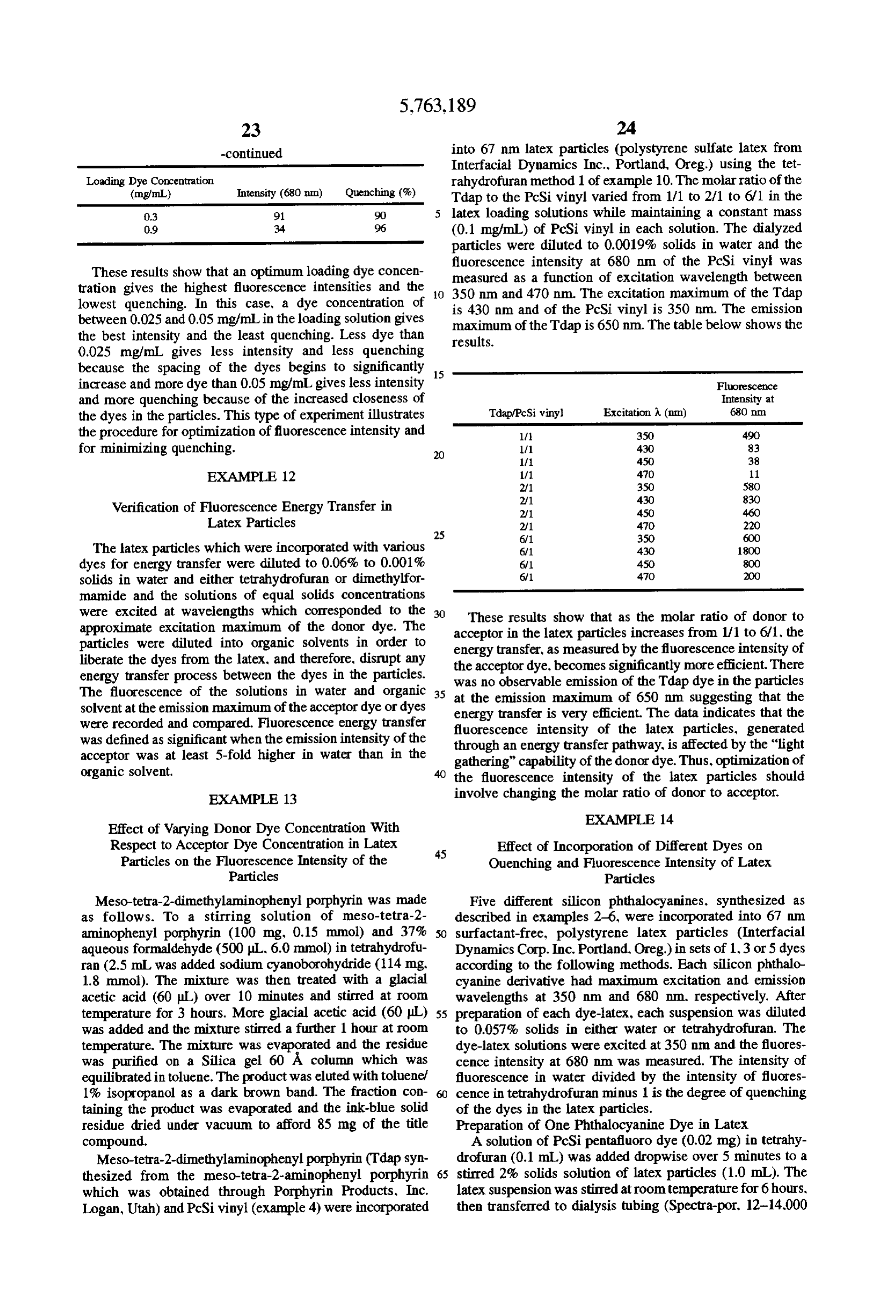
Page 22
molecular weight cutoff, Spectrum, Houston, Tex.) and the dye-latex solution was dialyzed against water for 12-15 hours at 4 C. The dye-latex solution was removed from Dyes Entrapped Entensity % Quenching dialysis and the solids concentration was adjusted to 1.6%. 1. 413 72 Preparation of Three Phthalocyanine Dyes in Latex 3 56 56
A solution which consists of PoSi pentafluoro, PcSi tri hexyl and PcSicyano dyes in equimolar amounts to total The data show that as the number of different dyes entrapped 0.02 mg dye in tetrahydrofuran (0.1 mL), was added drop into the latex goes from 1 to 3 to 5, the fluorescence intensity wise over 5 minutes to a stirred 2% solids solution of latex 10 increases because the quenching in the particles decreases. particles (1.0 mL). The latex suspension was stirred at room EXAMPLE 1.5 temperature for 6 hours, then transferred to dialysis tubing
(Spectra-por. 12-14,000 molecular weight cutoff, Spectrum, Preparation and Characterization of Fluorescence Houston, Tex.) and the dye-latex solution was dialyzed Energy Transfer Dye Latex (Table 1) and against water for 12-15 hours at 4°C. The dye-latex solution 15 Fluorescent Latex Incorporating Hybrid was removed from dialysis and the solids concentration was Phthalocyanine Derivatives (Table 2) adjusted to 1.6%. A variety of fluorescent energy transfer latexes were Preparation of Five Phthalocyanine Dyes in Latex prepared with various donor and acceptor dye molecules. Table 1 shows the loading concentrations of the respective
A solution which consists of PCSi pentafluoro. PcSi donor and acceptor dyes, the mole ratio of the donor and trihexyl, PeSicyano, PeSi vinyl and PcSi methyl ester dyes 20 acceptor dyes, the dye loading solvent system as described in equimolar amounts to total 0.02 mg dye in tetrahydrofu- in Example 10 and the excitation and emission wayelengths ran (0.1 mL), was added dropwise over 5 minutes to a stirred and A.site ES f each Eise at the 2% solids solution of latex particles solution (1.0 mL). The lar E. E. wipei late E. st ES gt f t 25 different diameter latexes. The fluorescence energy transfer lecular weight cut R S E. E. p T d th efficiency of the entries is greater than 80%. The dye system molecular weight cutoft. Spectrum, Houston, ex.) and the represented in line 56 is a fluorescence energy transfer dye-latex solution was dialyzed against water for 12-15 compound (FET compound) so that the donor and acceptor R. at 4 t". yar A. Were ity. pair reside in the molecule before incorporation into latex. - o s 4.
ysis and the 'lo solids concentration was adjus O Table 2 shows the characteristics of latex particles incor 1.6%. porated with hybrid phthalocyanine derivatives as described The table that follows illustrates the results of the fluo- in Example 10 and the fluorescence intensity at the specified rescence experiments. Solids concentration,
TABLE 1.
MOLE SOLVENT
LOADING LOAONG DONOR: SYSTEM EMISSION
CONC. CONC. MOLE (LATEX INTENSITY MAXIMUM
DONORDYE (mg/mL) ACCEPTOR OTE (mg/mL) ACCEPTOR SIZE) (% SOLID) (EXCIT) 1. trans-4-4-(Dibutyl amino) 0.12 Silicon phthalocyanine 0. 2:1 THF 340 679 in styryl-1-methyl pyridinium iodide mg/mL bis(dimethylvinylsilyl- mg/mL (0.067 (0.001.9%) (475 m) oxide) In) 2. trans-4-4-(Dibutyl amino) O. Silicon 2,3-naphthalo- 0.23 1:1 DMF 347 789 mm. styryl-1-methyl pyridinium iodide mg/mL cyanine bis(dimethyl- mg/mL. (0.067 (O.057%) (475 mm) vinylsilyloxide) Em) 3. trans-4-4-(Dibutyl amino) O. 1,1-Dihexyl-3,3,3,3'- 0.144 1:1 DMF 688 688 am styryl-1-methyl pyridinium iodide mg/mL tetramethylindodicarbo- mg/mL (0.067 (0.057%) (645 mm) cyanine iodide Em) 4. Meso-tetra-2-aminophenyl 0.18 Silicon phthalocyanine 0.1 2: THF 1000 679 m porphine mg/mL bis(dimethylvinylsilyl- mg/mL (O.202 (0.000.95%) (420 m) oxide) in) 5. Meso-tetra-2-aminophenyl 0. 1,1-Dihexyl-3,3,3,3'- 0.098 1:1 DMF 157 676 mm porphine mg/mL tetramethylindodicarbo- mg/mL (0.067 (0.0019%) (645 m) cyanine iodide Em) 6. Meso-tetra-2- 0.21 Silicon phthalocyanine 0.1 2: THF 209 679 mm. dimethylaminophenyl porphine ngfinil bis(dimethylvinyl- Ing/mL. (0.412 (0.00095%) (430 m) silyloxide) Ern) 7. 3-Ethyl-3'-ethyl carboxyethyl- 0.056 Silicon 2,3-naphthalo- O.25 4:1 DMF 289 85 in thiadicarbocyanine iodide mg/mL cyanine bis(dimethyl- mg/mL. (0.067 (0.057%) (650 m) vinylsilykoxide) Em) 8. 1,1-Dioctadecyl-3,3,3,3,3'- O.036 Silicon 2,3-naphthalo- O.03 4:1 DMF 324 787 m tetramethyl-indodicarbocyanine Ingm cyanine bis(dimethyl- mg/mL. (0.067 (0.057%) (650 m) perchlorate vinylsilyloxide) in) 9. 1.1'-Diethyl-3,3,3',3'- O.078 Silicon 2,3-naphthalo- 0.025 6: OMF 23 787 mm tetramethylindodi-carbocyanine mg/mL. cyanine bis(dimethyl- gfrnL. (0.067 (0.057%) (635 m) iodide vinylsilyloxide) Im) 10, 1,1'-Dihexyl-3,3,3',3'- O.94 Silicon 2,3-naphthalo- 0.025 6:1 DMF 907 783 Inn tetramethylindodicarbocyanine IngimTL cyanine bis(dimethyl- mg/mL (0.067 (0.057%) (635mm) iodide vinylsilyloxide) im) 11. 3,3'-Diethyl 0.03 Silicon 2,3-naphthalo- 0.025 1:1 DMF 12 788 in thiadicarbocyanine iodide mg/mL. cyanine bis(dimethyl- mg/mL (0.067 (0.057%) (650 nm)
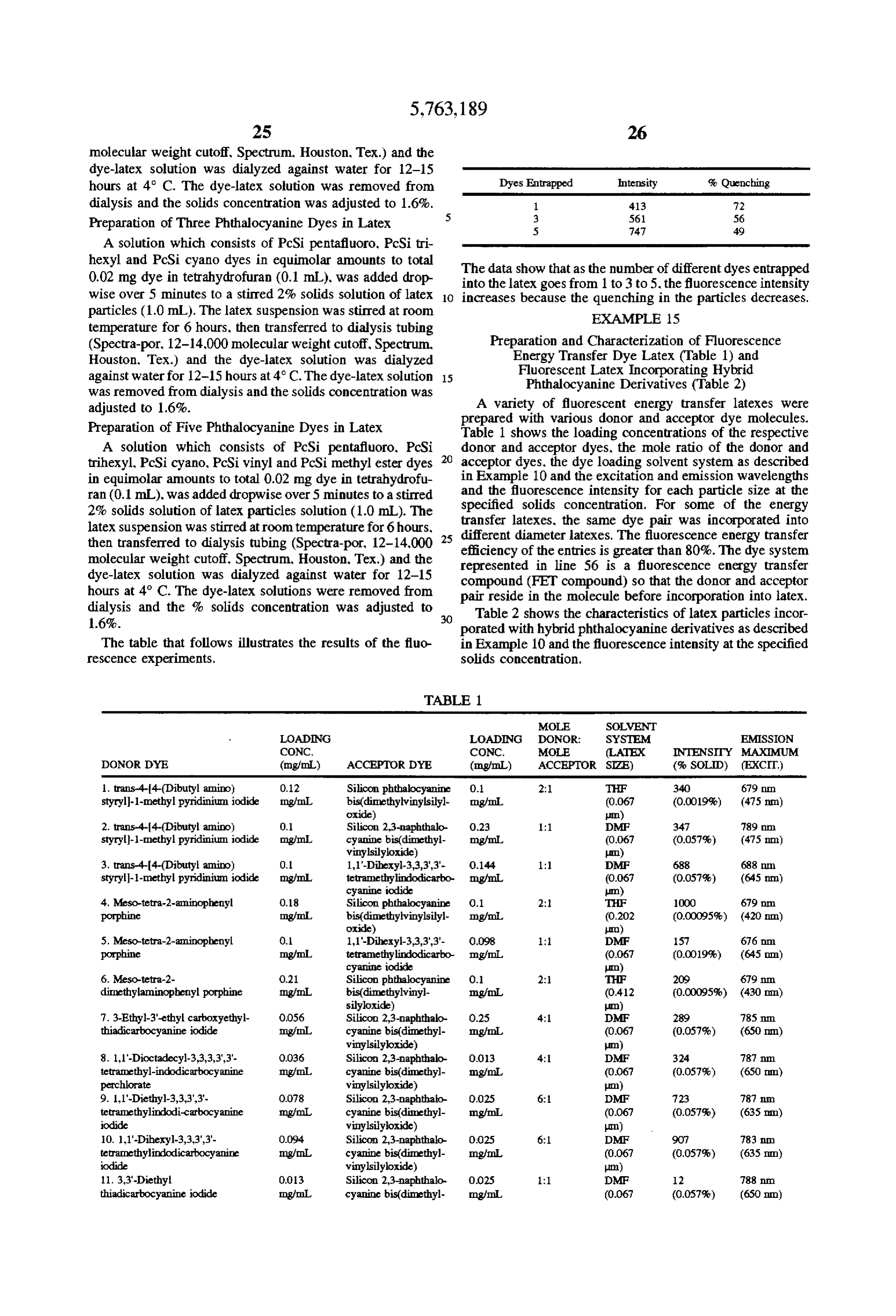
Page 23
TABLE 1-continued
MOLE SOLVENT
LOADING LOADING DONOR: SYSTEM EMISSION
CONC. CONC. MOLE (LATEX INTENSTTY MAXIMUM
DONOR DYE (mg/mL) ACCEPTOR DYE (mg/mL) ACCEPTOR SIZE) (% SOLID) (EXCIT)
12. 3,3'-Dipropyl O.O13 Silicon 2.3-naphthalo- O.025 1:1 DMF 65 788 nm. thiadicarbocyanine iodide mg/mL cyanine bis(dimethyl- mg/mL. (0.067 (0.057%) (660 nm)
13. 19-Dimethyl-methylene 0.008 Silicon 2.3-naphthalo- 0.025 1: DMF 57 788 in blue, chloride mg/mL. cyanine bis(dimethyl- mg/mL (0.067 (0.057%) (650 nm)
14. N,N-Di(3-trimethyl- 0.013 Silicon 23- 0.025 1: DMF 63 788 in ammoniumpropyl) thia- mg/mL naphthalocyanine mg/mL (0.067 (0.057%) (650 mm) dicarbocyanine tribromide bis(dimethylvinyl- un) silyloxide) 15. 1,1,3,3,3,3'-Hexamethyl- 0.012 Silicon 2,3-naphthalo- O.O25 1:1 DMF 33 788 nin indo-tricarbocyanine perchlorate mg/mL cyanine bis(dimethyl- mg/mL. (0.067 (0.057%) (650 nm)
16. N-(3-Triethyl- 0.014 Silicon 2,3-naphthalo- 0.025 1:1 DMF 55 788 mon ammoniumpropyl)-4-(4-(p- mg/mL cyanine bis(dimethyl- mg/mL (0.067 (0.057%) (500 nm) dibutylaminophenyl) butadienyl) vinylsilyloxide) un) pyridium, dibromide 17. 1,1,3,3,3',3'-Hexamethyl- 0.015 Silicon 2,3-naphthalo- OO2S 1:1 DMF 8 788 mm 4,4'-5,5-dibenzo-2,2'-indo- mg/mL. cyanine bis(dimethyl- mg/mL (0.067 (0.057%) (650 nm) tricarbocyanine perchlorate vinylsilyloxide) Im) 18. Fluoroscein 0.264 Silicon phthalocyanine 0.1 6: THF 57 683 mm. Ing/mL bis(dimethylvinyl- mg/mL (0.067 (0.057%) (485 nm)
19. Chlorophyll B 0.087 Silicon 2,3-naphthalo- 0.025 4: THF 72 783 nm. mg/mL cyanine bis(dimethyl- mg/mL (0.067 (0.057%) (440 nm)
20. Chlorophyll B 0.244 Silicon phthalocyanine 0.1 2: THF 140 679 mm mg/mL bis(dimethylvinyl- mg/mL. (0.067 (0.0019%) (440 nm)
21. trans-4-4-(Dibutyl 0.181 Silicon phthalocyanine 0.07 4:1:1 THF 300 681 lim amino)styryl-1-methyl pyridinium mg/mL. bis(dimethylpenta- mg/mL (0.067 (0.0019%) (475 nm) iodide fluorophenylsilyloxide) in)
Silicon phthalocyanine 0.05
oxide) 22. trans-4-4-(Dibutyl amino) OO2 Silicon phthalocyanine 0.04 4:1:1:1 THF 206 681 mm styryl-1-methyl pyridinium iodide mg/mL. bis(trihexylsilyloxide) mg/mL. (0.067 (0.001.9%) (475 nm)
Silicon phthalocyanine 004
phenylsilyloxide)
Silicon phthalocyanine 0.03
oxide) 23. 3-Ethyl-3-carboxyethylthia- 0.013 Silicon 2,3-naphthalo- 0.025 1:1 DMF 76 788 mm dicarbocyanine iodide mg/mL. cyanine bis(dimethyl- mg/mL (0.067 (0.057%) (625 nm)
24. 3-Ethyl-3'-ethyl-carboxy- 0.013 Silicon 2,3-naphthalo- 0.025 :1 DMF 135 788 in ethyloxathiadicarbocyanine iodide ngmL cyanine bis(dimethyl- mg/mL (0.067 (0.057%) (630 nm)
25. 3,3'-Diethylthia- 0.013 Silicon 2,3-naphthalo- 0.025 1:1 DMF 59 787 m dicarbocyanine iodide mg/mL. cyanine bis(dimethyl- mg/mL (0.067 (0.057%) (660 nm)
26. 3,3'-Diethyloxa- 0.012 Silicon 2,3-naphthalo- O.O25 1:1 DMF 57 787 mm dicarbocyanine iodide mg/mL cyanine bis(dimethyl- mg/mL. (0.067 (0.057%) (590 nm)
27. 1,1'-Dihexyl-3,3,3,3'- 0.094 Silicon 2,3-naphthako- O.O25 6:1;2 DMF 127 788 mm tetramethyl-indodicarbocyanine Ingfm L. cyanine bis(dimethyl- mgmL (0.431 (O.057%) (650 nm) iodide vinylsilyloxide) um CML)
Silicon naphthalocyanine 0.05
maleimidosilyloxide) 28. 1.1'-Dihexyl-3,3,3,3'- O.09.4 Silicon 2,3-naphthalo- 0.025 6:1:2 OMF 193 788 in tetramethyl-indodicarbocyanine mg/mL. cyanine bis(dimethyl- mg/mL (0.431 (0.057%) (635 nm) iodide vinylsilyloxide) um CML)
Silicon phthalocyanine 0.05
maleimidosilyloxide) 29. 1,1'-Dihexyl-3,3,3',3'- OO3 Silicon 2,3-naphthalo- O.05 1:1 DMF 275 788 mm
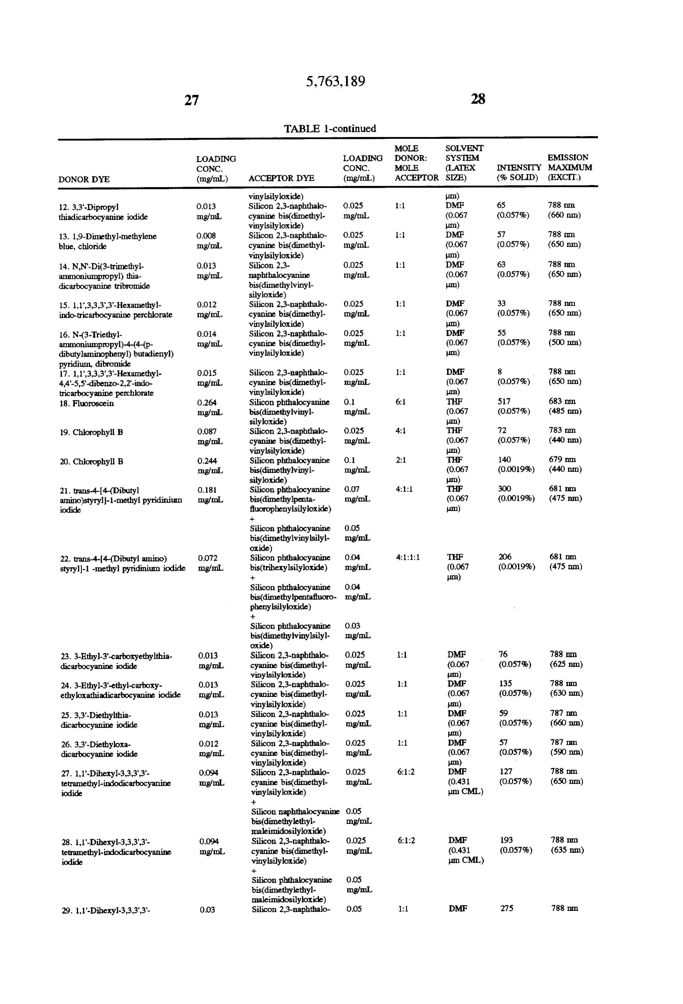
Page 24
Drawing sheet — no readable text.
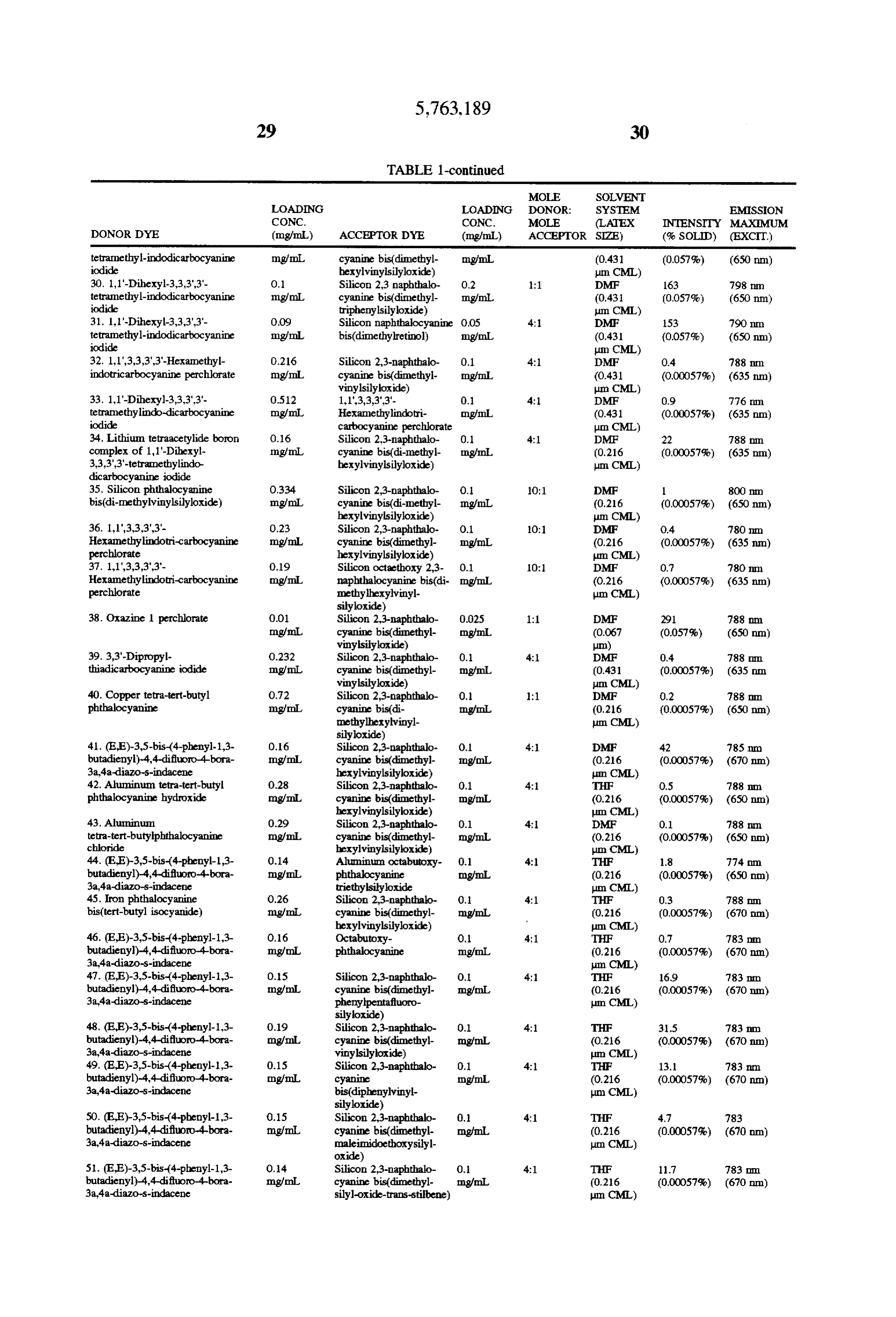
Page 25
Drawing sheet — no readable text.
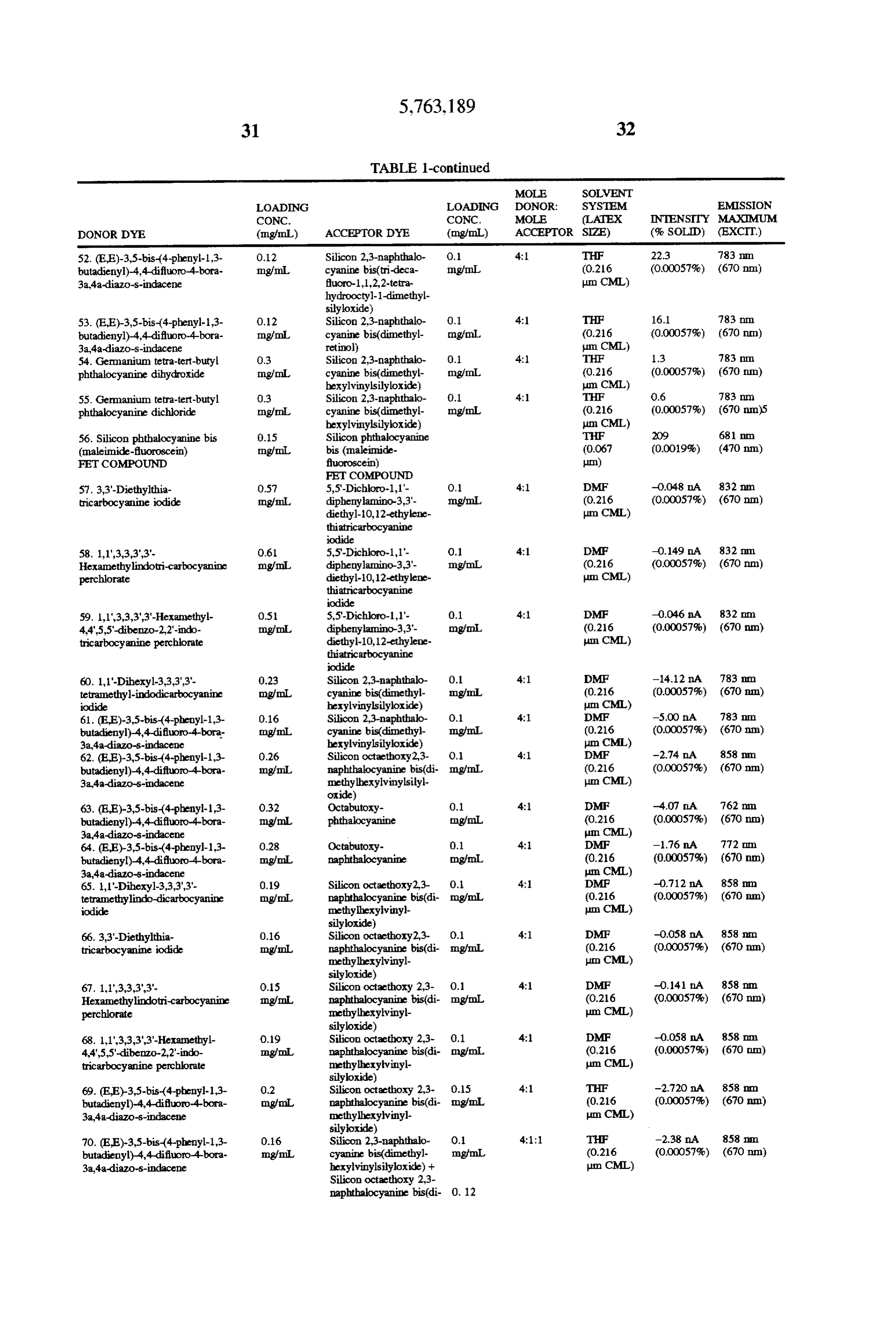
Page 26
TABLE 1-continued
MOLE SOLVENT
LOADING LOADING DONOR: SYSTEM EMISSION
CONC. CONC. MOLE (LATEX NTENSITY MAXIMUM
DONOR DYE (mg/mL) ACCEPTORDYE (mg/mL) ACCEPTOR SIZE) (% SOLID) (EXCIT)
oxide) 71. Silicon phthalocyanine O.36 5,5-Dichloro-1,1- 0.1 4:1 THF -8.10 nA 832 nun. bis(di-methylvinylsilyloxide) IngfrnL diphenylamino-3,3'- migfin (0.216 (0.00057%) (670 nm)
thiatricarbocyanine perchlorate 72. Tetrakis(4-cumyl-phenoxy) 0.48 Silicon 2,3-naphthalo- O. 4: THF -O.39. A 783 m phthalocyanine ragm cyanine bis(dimethyl- mg/mL (0.216 (0.00057%) (670 nm)
73. Tetrakis(4-cumyl-phenoxy) 0.68 5,5'-Dichloro-1'- 0.1 4: THF -0.128 mA 832 mm phthalocyanine Img/mL diphenylamino-3,3'- Ing/mL (0.216 (0.00057%) (670 nm)
thiatricarbocyanine perchlorate 74. Tetrakis(phenylthio) O34 Silicon 2,3-naphthalo- 0.1 4:1 THF -0.374. A 788 In phthalocyanine Ingfin cyanine bis(dimethyl- mg/mL. (0.216 (0.00057%) (670 nm)
75. Tetrakis(phenylthio) O.28 5,5-Dichloro-11'. O.1 4: THF -0.109 nA 832 m phthalocyanine Ingril diphenylamino-3,3'- mg/mL. (0.216 (0.00057%) (670 nm)
thiatricarbocyanine perchlorate 76. (EE)-3,5-bis-(4-phenyl-1,3- 0.24 Tin octabutoxy 2,3- O. 4:1 THF -1.724 nA 900mm butadienyl)-4,4-difluoro-4-bora- mg/mL. naphthalocyanine mgm. (0.216 (0.00057%) (670 nm) 3a,4a-diazo-s-indacene dichloride um CML) 77. Tetrakis 0.36 Tin octabutoxy 2,3- O. 4:1 THF -0.162 nA 900 m (4-cumylphenoxy) phthalocyanine mg/mL. naphthalocyanine mg/m. (0.216 (0.00057%) (670 nm)
78. Tetrakis(phenylthio) 0.26 Tin octabutoxy 2,3- 0. 4:1 THF -0.061 A >900 mm. phthalocyanine mg/mL. naphthalocyanine mg/mL. (0.216 (0.00057%) (670 mm)
79. Germanium tetra-tert-butyl 0.42 5,5-Dichloro-1'- O. 4:1 HF -0.109 IA 900 nm. phthalocyanine dihydroxide mg/mL. diphenylamino-3,3'- mg/mL (0.216 (0.00057%) (670 nm)
thiatricarbocyanine perchlorate 80. Germanium tetra-tert-butyl 0.22 Tin octabutoxy 2,3- 0.1 4:1 THF -0.045 A >900 m phthalocyanine dihydroxide mgn naphthalocyanine mg/mL (0.216 (0.00057%) (670 nm)
81. Germanium tetra-tert-butyl 0.2 Tin octabutoxy 2,3- 0.1 4:1 THF -0.042 nA >900 m phthalocyanine dihydroxide mg/mL naphthalocyanine bis mg/mL. (0.216 (0.00057%) (670 nm)
82. Germanium tetra-tert-butyl 0.42 5,5'-Dichloro-1,1- 0.1 4:1 THF -008. A 832 m phthalocyanine dichloride Ingfm. diphenylamino-3,3'- mg/mL. (0.216 (0.00057%) (670 nm)
thiatricarbocyanine perchlorate 83. Germanium tetra-tert-butyl 0.22 Tin octabutoxy 2,3- O. 4: THF -0.052 nA >900 in phthalocyanine dichloride Englin. naphthalocyanine mg/mL. (0.216 (0.00057%) (670 nm)
84. Germanium tetra-tert-butyl 0.2 Tin octabutoxy 2,3- 0.1 4:1 THF -0.050 A SOO in phthalocyanine dichloride Ingm naphthalocyanine bis mg/mL. (0.216 (0.00057%) (670 nm)
85. (EE)-3,5-bis-(4-phenyl-1,3- 0.16 Silicon 2,3-naphthalo- 0.1 4:1:1 THF -0.35 A 858 m. butadienyl)-4,4-difluoro-4-bora- mg/mL. cyanine bis(dimethyl- mgmL (0.216 (0.00057%) (670 nm) 3.a4-a-diazo-s-indacene hexylvinylsilyloxide) + Im CML)
thiatricarbocyanine perchlorate 86. (EE)-3,5-bis-(4-phenyl-1,3- 0.24 5,5-Dichloro-1,1'- O. 4:1 THF -2.23OA 832 min butadienyl)-4,4-difluoro-4-bora- ngfm. diphenylamino-3,3'- mg/mL (0.216 (0.00057%) (670 mm) 3a,4-a-diazo-s-idacene diethyl-10,12-ethylene- um CML) thiatricarbocyanine perchlorate 87. 1,1'-Dihexyl-3,3,3',3'- 0.34 5,5-Dichloro-1,1'- O. 4: THF -O.S.45 A, 823 on tetramethyl-indodicarbocyanine mg/mL diphenylamino-3,3'- Ing/mL (0.216 (0.00057%) (670 nm) iodide diethyl-10,12-ethylene- um CML) thiatricarbocyanine perchlorate 88. (EE)-3,5-bis-(4-phenyl-1,3- 0.16 Silicon 2,3-naphthalo- O.O7 4:1:1 TF 49 783 a.m. butadienyl)-4,4-difluoro-4-bora- mg/mL. cyanine bis(dimethyl- mg/mL (0.216 (0.00057%) (670 m)
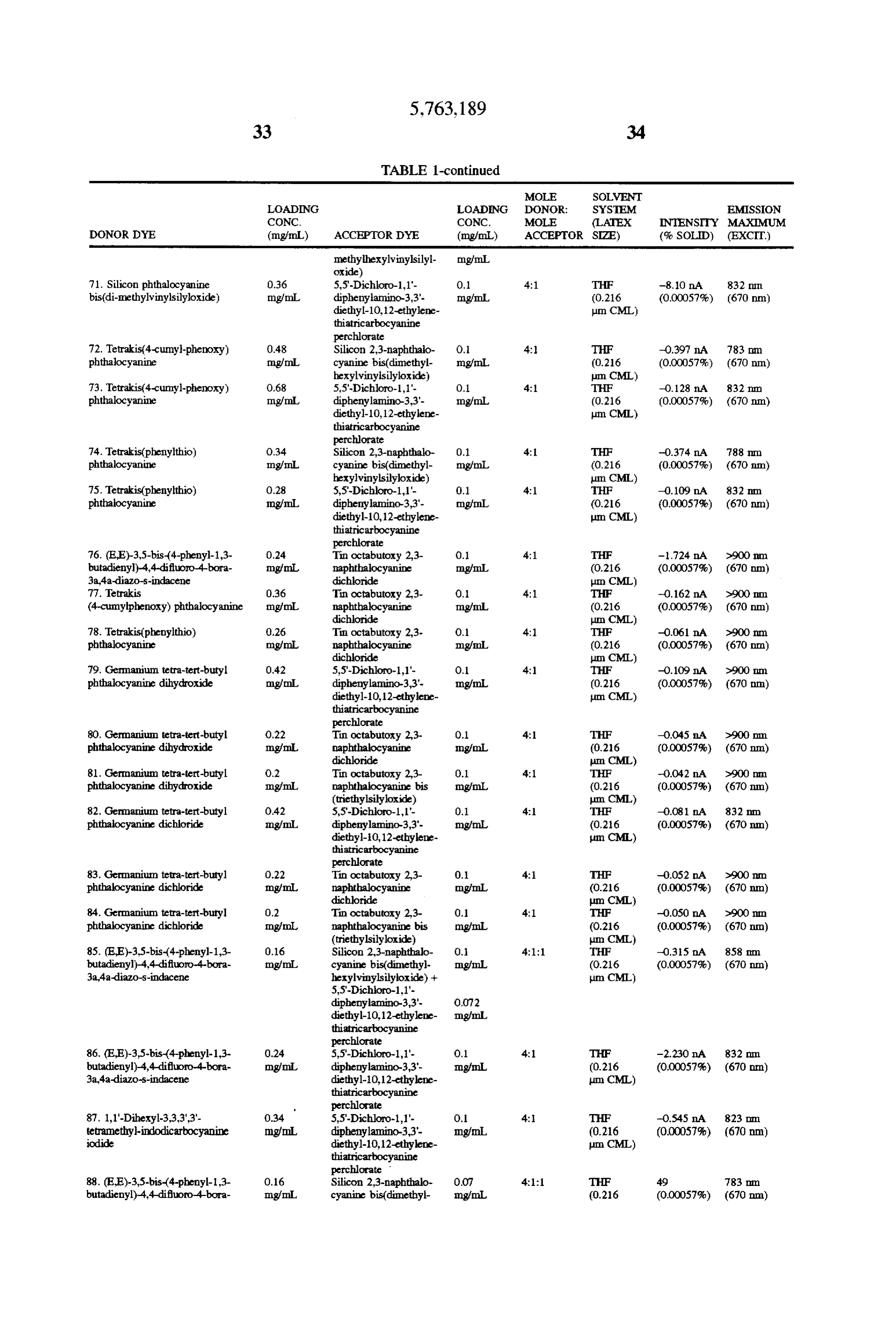
Page 27
TABLE 1-continued
MOLE SOLVENT
LOADING LOADNG DONOR: SYSTEM EMISSION CONC. CONC. MOLE (LATEX INTENSY MAXIMUM DONORDYE (mg/mL) ACCEPTOR OYE (mg/mL) ACCEPTOR SIZE) (% SOLID) (EXCIT) 3.a4-a-diazo-s-indacene hexylvinylsilyloxide) + im. CML) Silicon 2,3-naphthalo cyanine bis(dimethyl- O.O.
oxide)
TABLE 2
LOADING
CONC. SOLVENT LATEX EMISSION
HYBRD COMPOUND (mg/mL) SYSTEM SIZE % SOLD INTENSTY MAXIMUM EXCITATION 1. Silicon di(1,6-diphenylnaphthalocyanine) 2.0 THF 0.216 0.00057% 50 760 nm. 650 nmi diphthalocyanine bis(dimethylhexyl- mg/mL um CML vinylsilyloxide) 2. Silicon di(1,6-diphenylnaphthalocyanine) 2.0 THF 0.216 OOOO57% O/O.5 765 m 650 m tetrafluorophthalocyanine mg/mL. um CML 825 nm. phthalocyanine
3. Silicon di(1,6-diphenylnaphthalocyanine) 1.5 THF 0.216 OOOO57%, O.S.O.3 77O In 650 m tetrafluorophthalocyanine Ingm. um CML 839 m. phthalocyanine bis(dimethylpentafluorophenylsily oxide) 4. Silicon di(1,6-diphenylnaphthalocyanine)) O. THF 0.216 OOOO5% 0.2 7S 650 m diphthalocyanine bis(dimethylpentafluoro- mg/mL um CML phenylsilyloxide) 5. Silicon di(1,6-diphenylnaphthalocyanine) 1.5 THF 0.216 OOOO57%. 19 7.58 m. 650 m di(tert-butyl-phthalocyanine) bis(dimethyl- mg/mL in CML hexyvinylsilyloxide)
EXAMPLE 16 Oreg.) was added quickly, at room temperature, while vor
Adsorption of Anti-Human Chorionic Gonadotropin texing to a solution consisting of anti-o hCG monoclonal (hCG) Antibody to Latex Particles antibody (0.12 mL, 10.3 mg/mL, Applied Biotech Inc. San A typical example of the adsorptions of an antibody to chloride, pH 8.2inand
Diego, Calif.) 20 mM sodium borate/150 mM sodium 0.1M potassium citrate, pH3, (0.6 mL).
dyed latex particles, prepared as described in Example 10, The solution incubated at room temperature for 5 minutes and of a complementary antibody to undyed latex particles, and was subjected to centrifugation in an Eppendorf centri both of which can be used in a sandwich assay for hCG, is outlined below. Those skilled in the art will recognize that fuge (2000xg for 5 min). The supernatant was removed, the various techniques are available to adsorb or to covalently pellet
was resuspended in 0.1M potassium phosphate, pH 7.
mL) and the suspension was subjected to centrifugation couple proteins, peptides, ligand analogues nucleotides and 45 as described above. This process was repeated 2 times more nucleic acids to latex particles. A solution of dye latex (0.1 and in the final mL, 2% solids. 412 nmi; entry 10, Table 1) was added centrifugation, the pellet was resuspended quickly while vortexing to a solution of anti-B hCG mono with 0.1M potassium phosphate, pH 7 (0.3 mL) to make 1% clonal antibody (0.2 mL, 6.6 mg/mL, Applied Biotech Inc., solids. This antibody latex is used on a solid phase, such as San Diego, Calif.) in 20 mM sodium borate/150 mM sodium a membrane, to capture the hCG-dye antibody latex conju chloride, pH 8.2. A solution of 0.1M potassium citrate, pH gate complex in a reaction mixture in an immunoassay for 3. (0.04 mL) was added quickly while vortexing to the hCG.
antibody latex solution at room temperature and the pH of EXAMPLE 17 the resulting solution was 3.5. The solution incubated at room temperature for 5 minutes, then a solution of 2M Immunoassay for hCG potassium borate, pH 9.7 (0.025 mL) was added quickly while vortexing to bring the pH to about 8.5. This latex The solid phase anti-a hCG latex solution (0.005 mL, 1% antibody conjugate was dialyzed (Spectra-por dialysis solids; example 16) can be applied to a 2 cm piece of 0.45 tubing, molecular weight cutoff of 300,000, Spectrum, micron nylon membrane (Millipore Corp., Boston, Mass.) Houston, Tex.) against 4 changes of 2 L each of 20 mM which has been treated with a 2% solution of condensed sodium borate/150 mM sodium chloride, pH 8.2 at 4 C. for milk to lower non-specific binding interactions. This men 4 days. The dialyzed latex conjugate was then removed from brane can be used as the solid phase onto which is captured the dialysis tubing and the solids concentration was calcu the hCG dye latex conjugate complex. Thus, an hCG assay lated to be 0.4%. This conjugate can be used for immunoas can be performed by addition of dye latex conjugate (0.025 says for hCG in serum. The latex has excitation and emission mL, example 16) to 0.1 mL samples of serum suspected of wavelengths of 650 nm and 780 nm, respectively. 65 containing hCG and also to 0.1 mL serum samples contain A solution of polystyrene sulfate latex (0.036 mL, 8.4% ing known amounts of hCG (10, 100, 300, 500 and 1000 solids, 1000 nmi; Interfacial Dynamics Corp., Inc., Portland mIU/mL). The serum samples should be incubated about 10
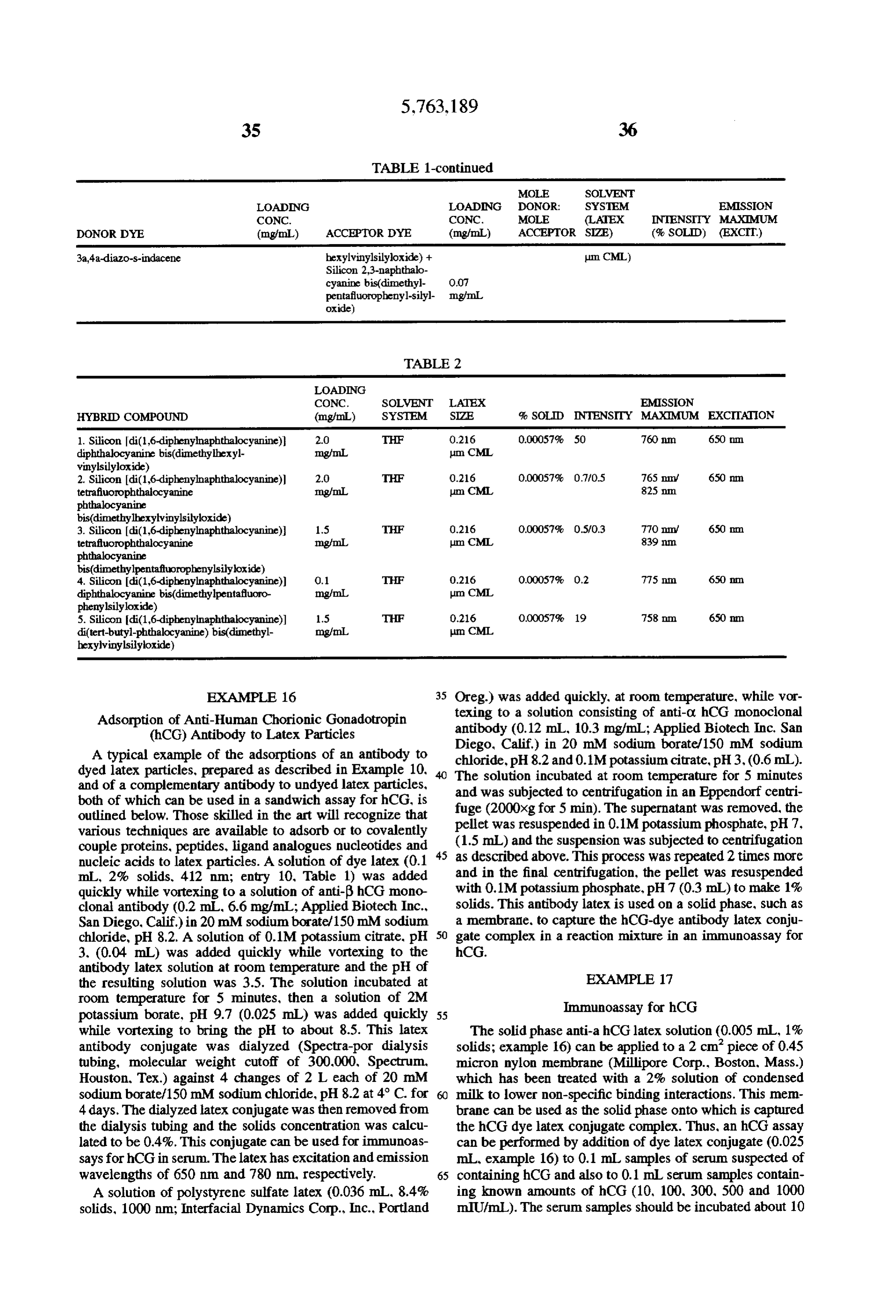
Page 28
minutes and then the samples are applied to the solid phase EXAMPLE 21 membrane containing the solid phase latex. The membrane should be placed over an absorbent so that the serum sample Synthesis of Silicon 2.3-Naphthalocyanine bis containing the dye latex conjugates flows through the solid (dimethylmaleimidoethoxysilyloxide) phase latex spot. After the serum solution has passed through A suspension of silicon 23-naphthalocyanine dihydrox the membrane, serum (0.5 mL) not containing the dye latex ide (39 mg. 0.05 mmol) in dimethylformamide (1 mL) conjugate is applied to the membrane to remove unbound containing dichlorodimethylsilane (13.5 L, 0.11 mmol) and dye latex conjugate. The latex spots on the membranes are imidazole (14 mg. 0.2 mmol) was stirred under argon at then placed in a front surface fluorescence accessory in a room temperature for 18 hours. The reaction mixture was fluorometer and the spot is excited at 650 nm and the O then treated with N-(2-hydroxyethyl)maleimide (35 mg. fluorescence intensity of the spot on each membrane is 0.25 mmol) and stirred for an additional 10 hours. The measured at 780 nm. The fluorescence intensity as a function reaction mixture was evaporated and the residue purified on of the hCG concentrations of the known samples is plotted. a silica column equilibrating with hexane, then toluene and The fluorescence intensities of the unknown h(G serum eluting the product with toluene/10% isopropanol as a green samples can be compared to the known hCG concentrations 15 band. The eluate containing the product was evaporated to from the graph. afford 3.5 mg of green solid.
EXAMPLE 1.8
EXAMPLE 22
Fluorometer for Measuring Near Infrared Emitting Synthesis of Silicon 2.3-Naphthalocyanine bis Dyes (dimethylsilyloxide-trans-stilbene)
The dye sample (2 mL sample volume in a 10 mmX10 mm A suspension of silicon 23-naphthalocyanine dihydrox quartz cuvette) was excited by a diode laser (Sun Laser ide (39 mg 0.05 mmol) in dimethylformamide (1 mL)
low-pass cutoff filter (Corion LS700, passes wavelengths 25 containing dichlorodimethylsilane (13.5 L, 0.11 mmol) and less than 700 nm). Fluorescence emission was detected at imidazole (14 mg., 0.2 mmol) was stirred under argon at 90° to the incident diode laser beam. The emitted light was room temperature for 2 hours. The reaction mixture was then treated with trans-4-hydroxystilbene (49 mg 0.25 mmol) collected and focused on a silicon photodiode (Melles Griot, and stirred for an additional 5 hours. The reaction mixture Cat. #13DS1009) by a condenser consisting of two aspheric lenses (Melles Griot, Cat #01 LAG 119). A high-pass cutoff 30 was evaporated and the residue purified on a silica column filter (Schott Glass RG715) in front of the Silicon photo equilibrating with hexane and eluting the product with diode blocked scattered laser light at 670 nm but passed ing toluene as a long green band. The toluene fraction contain emitted light at wavelengths larger than 715 nm. The pho the product was evaporated to afford 4 mg green solid. tocurrent from the silicon photodiode was amplified and EXAMPLE 23 displayed by a current amplifier in nanoamps ("na"), 35
(Melles Griot, Cat. #13 AMP 003). In some instances, 12 nm Synthesis of Silicon 2.3-Naphthalocyanine bis band filters were placed in front of the silicon photodiode (dimethylhexylvinyl-silyloxide) with center wavelengths at 730 nm, 790 nm, 850 nm, and 900 nm. A suspension of silicon 2.3-naphthalocyanine dihydrox ide (39 mg 0.05 mmol) in dimethylformamide (1 mL)
EXAMPLE 19 containing 7-oct-1-enyldimethylchlorosilane (32 L, 0.125 Synthesis of Silicon 23-Naphthalocyanine bis mmol) and imidazole (7 mg, 0.1 mmol) was stirred under (diphenylvinylsilyl-oxide) argon at room temperature for 18 hours. The reaction mixture was evaporated and the residue purified on silica
A suspension of silicon 23-naphthalocyanine dihydrox 45 column equilibrating with hexane and eluting the product ide (39 mg, 0.05 mmol) in dimethylformamide (0.5 mL) with toluene as a green band. The toluene fraction contain containing diphenylvinylchlorosilane (28 L, 0.125 mmol) ing the product was evaporated and the residue treated with and imidazole (7 mg, 0.1 mmol) was stirred under argon at hexane to afford a dark green solid and light green super room temperature for 18 hours. The reaction mixture was natant. The mixture was centrifuged, the supernatant evaporated and the residue purified on a silica column SO removed and the solid treated with more hexane and cen equilibrating with hexane and eluting the product with trifuged. The supernatant was again removed and the solid toluene as a long green band. The toluene fraction contain dried under vacuum to yield 7.3 mg of product. ing the product was evaporated to afford 5 mg green solid.
EXAMPLE 24
Synthesis of Silicon 2,3-Naphthalocyanine bis
Synthesis of Silicon 2.3-Naphthalocyanine bis (tridecafluoro-1,1-22-tetrahydrooctyl-1- (triphenylsilyloxide) dimethylsilyloxide)
A suspension of silicon 23-naphthalocyanine dihydrox A suspension of silicon 23-naphthalocyanine dihydrox ide (39 mg. 0.05 mmol) in dimethylformamide (1 mL) ide (39 mg 0.05 mmol) in dimethylformamide (1 mL) containing triphenylchlorosilane (37 mg, 0.125 mmol) and containing (tridecafluoro-1.1.2.2-tetrahydrooctyl)-1- imidazole (7 mg. 0.1 mmol) was stirred under argon at room dimethylchlorosilane (37 L, 0.1 mmol) and imidazole (7 temperature for 18 hours. The reaction mixture was evapo mg 0.1 mmol) was stirred under argon at room temperature rated and the residue purified on a silica column equilibrat for 2 hours. The reaction mixture was evaporated and the ing with hexane and eluting the product with toluene as a 65 residue purified on a silica column equilibrating with hexane green band. The toluene fraction containing the product was and eluting with hexane/20% toluene followed by hexane/ evaporated to afford 2.5 mg green solid. 40% toluene to afford the product as a green band. The
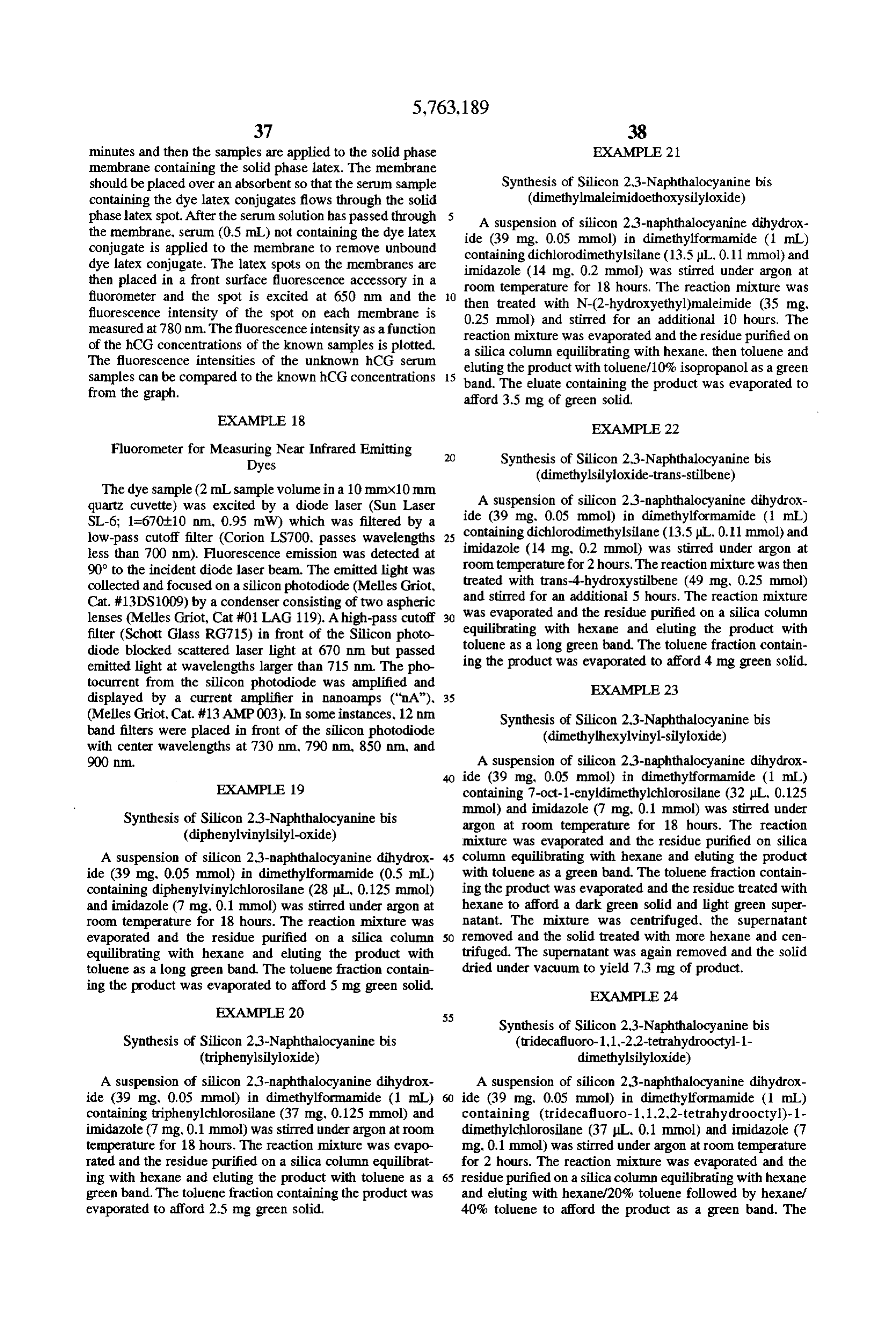
Page 29
product eluate was evaporated and the residue treated with UV-vis (tetrahydrofuran) ((nm), e(M'cm')): 855. hexane to afford a green solid. The mixture was centrifuged, 370000.
the supernatant removed and the solid treated with more Infrared Spectrum(KBr): 3074. 2958. 2924, 2854. 1589, hexane and recentrifuged. The supernatant was again 1417, 1373, 1348, 1262, 1238, 1194, 1161, 1111. 1044, removed and the green solid dried under vacuum to yield 7.5 102.5, 933, 909, 844, 799, 760 cm. mg of product. 'H-NMR (500 MHz, CDCL): 89.0 (m. 25-Nc), 7.9 (m, EXAMPLE 25 3.4-Nc), 5.3 (m, -CH2). 4.6 (m. vinyl-CH2).3.5 (m. vinyl
Synthesis of Silicon 23-Naphthalocyanine bis 10
A suspension of silicon 23-naphthalocyanine dihydrox EXAMPLE 29 ide (39 mg 0.05 mmol) in dimethylformamide (1 mL) Synthesis of Silicon Phthalocyanine bis containing dichlorodimethylsilane (13.5ul, 0.11 mmol) and 15 (dimethylmaleimidofluorescein) imidazole (14 mg., 0.2 mmol) was stirred under argon at room temperature. After 20 minutes, the reaction mixture Fluorescein ATP (0.5 mg, 1.05 mol) was treated with a was treated with all-trans-retinol (72 mg 0.25 mmol) and solution of 0.12M potassium carbonate in 80% methanol (52 stirred for an additional 1 hour. The reaction mixture was L). After 5 minutes, the hydrolysis solution was quenched evaporated and the residue purified on a silica column 20 by the addition of 0.5M potassium phosphate/0.1M potas equilibrating with hexane and eluting the product with sium borate, pH 7.0 in 1N HCl (10 L). The quenched toluene as a long green band. The toluene fraction contain hydrolysis solution was evaporated to dryness, redissolved ing the product was evaporated and the residue treated with in dimethylformamide (100 L) and the resulting solution hexane to yield a dark green solid and light green superna added to silicon phthalocyanine b is tant. The mixture was centrifuged, the hexane removed and 25 (dimethylmaleimidosilyloxide) in a 1.0 mL serum vial. The the solid dried under vacuum to yield 10 mg of final product. reaction mixture was then stirred at room temperature for 1 hour. The crude product was then chromatographed on two
EXAMPLE 26 3"x3" silica plates using toluene/20% dimethylformamide. Synthesis of Silicon Octaethoxy-2,3- After elution, the plates were dried under vacuum and
rechromatographed for a better separation. The product band naphthalocyanine Dichloride was scraped off, and treated with dimethylformamide (5 4.9-Diethoxy-1,3-diiminobenziflisoindoline (0.6 g) was mL), vortexed 30 seconds and filtered from the silica. The added under argon to freshly distilled quinoline (12 mL). filtrates rescent were evaporated to give 0.55 mg of greenish fluo solid.
After stirring for 10 minutes, silicon tetrachloride (4.0 mL) was added and the reaction mixture was heated at 190° C. for 35 EXAMPLE 30 1 hour. The reaction mixture was cooled to room temperature, and water (120 mL) was added slowly to Synthesis of Tin(IV) Octabutoxy-2,3- hydrolyze the unreacted silicon tetrachloride. The blue naphthalocyanine bis(triethylsilyloxide) black precipitate was filtered off and washed with methanol and acetone. A mixture of triethylsilanol (77 uL). sodium (3.5 mg), and UV-vis (methylene chloride) (nm)): 768. 869. Xylenes (5 mL) was refluxed under argon for 1 hour and slightly cooled. A solution of tin(IV) octabutoxy-2,3-
EXAMPLE 27 naphthalocyanine dichloride (74 mg) in xylenes (5 mL) was added to the solution formed and the mixture was refluxed
Synthesis of Silicon Octaethoxy-2,3- 45 for 20 minutes. The resultant was washed twice with water Naphthalocyanine Dihydroxide (25 mL each time), dried (MgSO), and evaporated to a dark red solid with a rotary evaporator. This solid was chromato
A suspension of silicon octaethoxy-2,3-naphthalene graphed (silica gel 70–230 mesh, 60 A 2x50 cm, toluene dichloride (1.96 g) in pyridine (15 mL) containing water (15 isopropanol), vacuum dried, and weighed (17 mg). mL) was refluxed for 18 hours. The suspension was cooled, UV-vis(tetrahydrofuran) ( (nm), e(M'cm)): 900, the blackprecipitate filtered and washed with water (10 mL). 50 174000.
The precipitate was dried under vacuum and weighed (1.37 g, purple powder). EXAMPLE 31 UV-vis (methylene chloride) ((nm)): 766, 867. Synthesis of Tin(IV) 2.3-Naphthalocyanine bis
EXAMPLE 28 (triethylsilyloxide)
Synthesis of Silicon Octaethoxy-2,3- A mixture of triethylsilanol (77 L), sodium (3.5 mg), and Naphthalocyanine bis(dimethylhexylvinylsilyloxide) Xylenes (8 mL) was refluxed under argon for 1 hour and slightly cooled. Tin(IV) 23-naphthalocyanine dichloride (45
A suspension of silicon octaethoxy-2,3-naphthalene dihy mg) was added to the solution formed, and the mixture was droxide (1.0 g) in dimethylformamide (20 mL) containing refluxed for 5 days. The suspension was filtered, and the 7-oct-1-enyldimethylchlorosilane (0.6 mL) and imidazole solid was washed (xylenes and water), vacuum dried, and (140 mg) was stirred under argon at room temperature for 24 weighed (41 mg). The solid was chromatographed (silica gel hours. The reaction mixture was evaporated with a rotary 70–230 mesh, 60 A 2x50 cm, methylene chloride evaporator, chromatographed (silica gel 70–230 mesh, 60 A. 65 tetrahydrofuran), vacuum dried, and weighed (26 mg). 2x50 cm, hexane-toluene(1:1)) vacuum dried, and weighed UV-vis(tetrahydrofuran) ( (nm), e(M'cm)): 700, (46 mg). 746; 786, 253000.
Page 30
Fluorescence (tetrahydrofuran) (max(nm)): 820. EXAMPLE 36 EXAMPLE 32 Synthesis of Tetrabromotetrabutoxy-2,3- naphthalocyanine
Synthesis of Tin(IV) 23-Naphthalocyanine bis 1,4-dibutoxynaphthalene-2,3-dicarbonitrile (161 mg) and (dimethylhexylvinylsilyloxide) 2,3-dibrono-6,7-dicyanonaphthalene (168 mg) were added A mixture of 7-Oct-1-enyl dimethylsilanol (186 mg), to a refluxing solution of lithium metal (35 mg) in 1-butanol (2 mL) under an argon atmosphere. The reaction solution
Sodium (7 mg), and xylenes (10 mL) was refluxed under was maintained at reflux for 2 hours, cooled, and stirred into argon for 4 hours and slightly cooled. Tin(IV) 2.3- naphthalocyanine dichloride (90 mg) was added to the O glacial acetic acid (10 mL). After 30 minutes, the solvent solution formed and the mixture was refluxed for 4 days. The was evaporated with a rotary evaporator and the residue suspension was filtered and the solid was washed with dissolved in methylene chloride (10 mL). The solution was xylenes (5 mL) and water (5 mL). The organic layer of the washed twice with 1N hydrochloric acid (10 mL each time). filtrate was separated, dried (MgSO), and evaporated with water (10 mL), dried (MgSO) and evaporated with a rotary a rotary evaporator. The residue was triturated twice with 15 evaporator. The residue was chromatographed (silica gel hexane (2 mL each time) to afford a bright green solid which 70–230 mesh, 60 A 2x50 cm, hexane-toluene), the solid was vacuum dried and weighed (8.5 mg). product triturated with hexane (2 mL), vacuum dried, and UV-vis (tetrahydrofuran) ( (nm), e(M'cm)): 670, weighed (8 mg).
EXAMPLE 33 EXAMPLE 37
Synthesis of Tin (IV) Octabutoxy-2,3- Synthesis of Di(1,6-dibutoxy-2,3-naphthalocyanine) naphthalocyanine Dichloride di(tetrafluorophthalocyanine) Tin tetrachloride (234 L) was added to a mixture of 25 1,4-Dibutoxynaphthalene-2,3-dicarbonitrile (161 mg) and octabutoxy-2,3-naphthalocyanine (310 mg) in dry dimeth tetrafluorophthalonitrile (100mg) were added to a refluxing ylformamide (15 mL) under an argon atmosphere and the solution of lithium metal (35 mg) in 1-butanol (2 mL) under mixture refluxed with stirring for 6 hours. The resultant was an argon atmosphere. The reaction solution was maintained allowed to cool, the suspension was filtered, and the dark red 30 at reflux for 1 hour, cooled, and stirred into glacial acetic solid was washed with dimethylformamide (5 mL) and acid (10 mL). After 30 minutes the solvent was evaporated water (5 mL), vacuum dried and weighed (288 mg). with a rotary evaporator and the residue dissolved in meth ylene chloride (10 mL). The solution was washed twice with
EXAMPLE 34 1N hydrochloric acid (10 mL each time), water (10 mL). dried (MgSO) and evaporated with a rotary evaporator. The
Synthesis of Tin(IV) Octabutoxy-2,3- 35 residue was chromatographed twice (silica gel 70-230 naphthalocyanine bis(dimethylhexylvinylsilyloxide) mesh, 60 A 2x50 cm hexane-toluene), the bright green A mixture of 7-Oct-1-enyl dimethylsilanol (186 mg), fraction vacuum dried and weighed (10 mg). sodium (7 mg), and xylenes (10 mL) was refluxed under UV-vis (tetrahydrofuran) ((nm), e(M'cm)): 679, argon for 5 hours and slightly cooled. Tin(IV) octabutoxy 25800; 752, 88200; 789, 76500.
2.3-naphthalocyanine dichloride (37 mg) was added to the Fluorescence (tetrahydrofuran) ((nm)): 815. solution formed, and the mixture was refluxed for 2 days. EXAMPLE 38 The resultant was washed with water (10 mL), dried Synthesis of DiC1,6-diphenyl-2,3-naphthalocyanine) (MgSO), and evaporated to a dark red solid with a rotary di(tetrafluorophthalocyanine) evaporator. This solid was chromatographed (silica gel 45 70–230 mesh, 60A,2x50 cm, toluene-isopropanol), vacuum 14-diphenylnaphthalene-2,3-dicarbonitrile (165 mg) and dried, and weighed (17 mg). tetrafluorophthalonitrile (100mg) were added to a refluxing UV-vis (tetrahydrofuran) ((nm), e(M' cm)): 785; solution of lithium metal (35 mg) in 1-butanol (2 mL) under 893, 227000. an argon atmosphere. The reaction solution was maintained Fluorescence(tetrahydrofuran) (A (nm)): 789. 50 at reflux for 1.5 hours, cooled, and stirred into glacial acetic acid (10 mL). After 30 minutes, the solvent was evaporated
EXAMPLE 35 with a rotary evaporator and the residue dissolved in meth ylene chloride (10 mL) The solution was washed twice with
Synthesis of 7-Oct-1-enyl Dimethylsilanol 1N hydrochloric acid (10 mL each time), water (10 mL). A solution of 7-oct-1-enyl dimethylchlorosilane (2.56 55 dried (MgSO), and evaporated with a rotary evaporator. mL) in ether (2 mL) was added dropwise over 1 hour to a The residue was chromatographed (silica gel 70-230 mesh, stirring mixture of triethylamine (1.5 mL), water (0.18 mL) 60 A 2x50 cm, hexane-toluene), the bright green fraction and ether (15 mL) in an ice/water bath. The resultant was vacuum dried and weighed (7 mg).
stirred a further 1 hour in the ice/water bath and filtered UV-vis (tetrahydrofuran) ( (nm), e(M'cm')): 747. washing the filtered solid with ether (10 mL). The filtrate 86800.
was evaporated with a rotary evaporator and the residue Fluorescence(tetrahydrofuran) ( (nm)): 760. partitioned between hexane (30 mL) and water (30 mL). The EXAMPLE 39 organic layer was separated, dried (MgSO) and filtered through silica gel (70-230 mesh, 60 A), washing with Synthesis of Dibutoxy-1,3-diiminobenzf hexane (100 mL). The filtrate was evaporated with a rotary 55 isoindoline evaporator to afford a colorless oil which was vacuum dried Anhydrous ammonia was slowly bubbled through a and weighed (1.06 g). stirred mixture of 1,4-dibutoxynaphthalene-2,3-
Page 31
dicarbonitrile (1.61 g), 25% sodium methoxide in methanol UV-vis (tetrahydrofuran) ((nm)): 600, 632, 666, 700, (1.14 mL), and dry 1-butanol (10 mL) for 30 minutes. With 724, 788.
continued ammonia introduction, the mixture was refluxed for 30 minutes. After the resultant had cooled, the solvent EXAMPLE 43 was removed under vacuum with a rotary evaporator. The Synthesis of Silicon di(1,6-diethoxy-2,3- residue was chromatographed (silica gel 70-230 mesh, 60 naphthalocyanine) Diphthalocyanine bis A 2x50 cm. hexane-toluene-isopropanol) and the yellow product treated with ether (10 mL), collected by filtration, (dimethylhexylvinylsilyloxide) washed with ether (10 mL), vacuum dried and weighed (517 A mixture of silicon di(1.6-diethoxy-2,3- mg). naphthalocyanine) diphthalocyanine dihydroxide (85 mg), "H-NMR (500 MHz. CDC1) 88.22 (m, 5.8-H). 7.65 (m. 7-Oct-1-enyl dimethylchlorosilane (256 ul), imidazole (68 6.7 -H), 4.23 (m. Y-CH), 1.97 (m, B -CH), 1.61 (m, mg), and dimethylformamide (2 mL) was stirred at room o, -CH2). 1.04 (t. -CH). temperature for 24 hours. The resultant was concentrated under vacuum with a rotary evaporator. The residue was
chromatographed (silica gel 70–230 mesh. 60 A 2x50 cm.
Synthesis of Diethoxy-1,3-diiminobenz|f hexane-toluene-isopropanol), vacuum dried, and weighed
Anhydrous ammonia was slowly bubbled through a 731, 822, 904.
stirred mixture of 1,4-diethoxynaphthalene-2.3- 20 dicarbonitrile (1.33 g), 25% sodium methoxide in methanol EXAMPLE 44 (1.14 mL). and dry ethanol (10 mL) for 20 minutes. With continued ammonia introduction, the mixture was refluxed Synthesis of Silicon di(1.6-diphenyl-2,3- for 2 hours. After the resultant had cooled, the solvent was 25 naphthalocyanine) Diphthalocyanine bis removed under vacuum with a rotary evaporator. The resi (dimethylhexylvinylsilyloxide) (FIG. 9). due was treated with methylene chloride (10 mL) and the A mixture of silicon di(1.6-diphenyl-2,3- product was collected by filtration, washed with water (5 naphthalocyanine) diphthalocyanine dihydroxide (30 mg), mL), methylene chloride (5 mL), vacuum dried and weighed 7-oct-1-enyl dimethylchlorosilane (115 L), imidazole (30 (766 mg). 30 mg) and dimethylformamide (650 L) was stirred at room EXAMPLE 41 temperature for 30 minutes. The resultant was concentrated under vacuum on the rotary evaporator. The residue was
Synthesis of Silicon di(1.6-diphenyl-2,3- chromatographed (silica gel 70–230 mesh, 60 A 2x50 cm, naphthalocyanine) Diphthalocyanine Dihydroxide hexane-toluene). vacuum dried and weighed (38 mg).
Silicon tetrachloride (231 L) was added to a mixture of 10,13-No), diphenyl-1,3-diiminobenzflisoindoline (470 mg) and 1,3- 0.68 (m, e -CH2), 7.94 (m, Ar-Nc), 7.95, 7.74 (3.4-Nc, 1112-Pc), diiminoisoindoline (97 mg) in freshly distilled quinoline (5 -1.22 (nm, B -CH2), 0.21 (m, 8-CH), -0.11 (m, Y-CH), mL) under an argon atmosphere and the mixture heated with -CH). -2.14 (m, o. -CH), -2.76 (s, stirring at 200° C. for 40 minutes. The resultant was allowed UV-vis(tetrahydrofuran) ((nm), e(M' cm)): 644; to cool slightly, treated with water (5 mL) and refluxed for 684; 718, 81100; 748.
5 minutes. The mixture was cooled, treated with ether (30 mL) and filtered washing the solid with ether (10 mL) and Fluorescence(tetrahydrofuran) ((nm)): 754. water (10 mL). The organic layer of the filtrate (which was EXAMPLE 45 dark green) was separated, washed with water (15 mL), 45 dried (MgSO) and evaporated with a rotary evaporator. The Synthesis of Tetrafluoro-1,3-diiminobenzf residue was chromatographed three times (silica gel 70-230 isoindoline mesh, 60 A 2x50 cm, hexane-methylene chloride), vacuum dried and weighed (55.5 mg). Anhydrous ammonia was slowly bubbled through a UV-vis (tetrahydrofuran) ((nm), e(M' cm)): 640; 50 stirred mixture of tetrafluorophthalonitrile (2.0 g). 25% 680; 714.67900; 742. sodium methoxide in methanol (2.3 mL), and dry 1-butanol Fluorescence (tetrahydrofuran) ((nm)): 750. (10 mL) for 20 minutes. With continued ammonia introduction, the mixture was refluxed for 1 hour. After the
EXAMPLE 42 resultant had cooled, the solvent was removed under 55 vacuum with a rotary evaporator. The residue was treated
Synthesis of Silicon di(1.6-diethoxy-2,3- with ether (50 mL) and the product was collected by naphthalocyanine) Diphthalocyanine Dihydroxide filtration, washed with water (10 mL), ether (10 mL). Silicon tetrachloride (137 L) was added to a mixture of vacuum dried and weighed (0.45 g).
diethoxy-1,3-diiminobenziflisoindoline (227 mg) and 1,3- EXAMPLE 46 diminoisoindoline (58 mg) in freshly distilled quinoline (3 mL) under an argon atmosphere and the mixture heated with Synthesis of Diphenyl-1,3-diiminobenz|f stirring at 200° C. for two hours. The resultant was allowed isolindoline to cool slightly, treated with water (3 mL) and refluxed for 5 minutes. The mixture was cooled, treated with ether (10 Anhydrous ammonia was slowly bubbled through a mL), and the dark blue solid product filtered off, washed 65 stirred mixture of 1.4-diphenylnaphthalene-2,3- with ether (10 mL) and water (10 mL), vacuum dried and dicarbonitrile (4.3 g), 25% sodium methoxide in methanol weighed (175 mg). (3.0 mL), and dry 1-butanol (25 mL) for 30 minutes. With
Page 32
continued ammonia introduction, the mixture was refluxed stirring at 200° C. for 1 hour. The resultant was allowed to for 1.5 hours. After the resultant had cooled, the solvent was cool slightly, treated with water (2 mL) and refluxed for 5 removed under vacuum with a rotary evaporator. The resi minutes. The mixture was cooled, treated with ether (10 mL) due was treated with methylene chloride (50 mL) and the and filtered washing the solid with water (5 mL) and ether product was collected by filtration, washed with water (10 5 (5 mL). The organic layer of the filtrate was separated, mL). methylene chloride (10 mL), vacuum dried and washed with water (10 mL), dried (MgSO) and evaporated weighed (3.68 g). with a rotary evaporator. The residue was chromatographed
EXAMPLE 47
(silica gel 70-230 mesh, 60 A 2x50 cm, methylene chloride). Vacuum dried and weighed (21 mg).
Synthesis of Silicon di(1.6-diphenyl-2,3-
naphthalocyanine) di(tetrafluorophthalocyanine)
Dihydroxide Fluorescence (tetrahydrofuran) ((nm)): 760.
Silicon tetrachloride (86 L) was added to a mixture of EXAMPLE 50 diphenyl-1,3-diiminobenzfisoindoline (174 mg) and 15 tetrafluoro-1,3-diiminoisoindoline (54 mg) in freshly dis Synthesis of Silicon di(1,6-diphenyl-2,3- tilled quinoline (1 mL) under an argon atmosphere and the naphthalocyanine) (tetrafluorophthalocyanine) mixture heated with stirring at 200° C. for 1 hour. The Phthalocyanine bis (dimethylhexylvinylsilyloxide) resultant was allowed to cool slightly, treated with water (1 O A mixture of silicon di(1,6-diphenyl-2,3- mL) and refluxed for 5 minutes. The mixture was cooled, naphthalocyanine) (tetrafluorophthalocyanine) phthalocya treated with ether (10 mL) and filtered washing the solid nine dihydroxide (10.5 mg), 7-oct-1-enyl dimethylchlorosi with water (2 mL) and ether (5 mL). The organic layer of the lane (38 L), imidazole (10 mg) and dimethylformamide filtrate was separated, washed with water (5 mL), dried (200 L) was stirred at room temperature for 30 minutes. (MgSO) and evaporated with a rotary evaporator. 25 The resultant was concentrated under vacuum on the rotary The residue was chromatographed (silica gel 70–230 evaporator. The residue was chromatographed (silica gel mesh, 60 A 2x50 cm, methylene chloride), vacuum dried 70-230 mesh, 60 A 2x50 cm, hexane-toluene), vacuum and weighed (18 mg). dried and weighed (4 mg). UV-vis (tetrahydrofuran) ((nm), e(M' cm)): 727, UV-vis(tetrahydrofuran) ((nm)): 732, 757, 794,816. 759, 809, 835. Fluorescence(tetrahydrofuran) ((nm)): 763, 830. Fluorescence (tetrahydrofuran) ((nm)): 685, 760, 840. EXAMPLE 51
EXAMPLE 48 Synthesis of Silicon di(1.6-diphenyl-2,3- 35 naphthalocyanine) (tetrafluorophthalocyanine)
Synthesis of Silicon di(1,6-diphenyl-2,3- Phthalocyanine bis naphthalocyanine) (1,6-diethoxyphthalocyanine) (dimethylpentafluorophenylsilyloxide) Phthalocyanine Dihydroxide A mixture of silicon di(1,6-diphenyl-2,3- Silicon tetrachloride (172 L) was added to a mixture of naphthalocyanine) (tetrafluorophthalocyanine) phthalocya diphenyl-1,3-diiminobenzfisoindoline (347 mg), diethoxy nine dihydroxide (10.5 mg), chlorodimethylpentafluorophe 1.3-diiminobenzfi soindoline (71 mg) and 1.3- nylsilane (28 ul), imidazole (10 mg) and diminoisoindoline (36 mg) in freshly distilled quinoline (2 dimethylformamide (200 L) was stirred at room tempera mL) under an argon atmosphere and the mixture heated with ture for 30 minutes. The resultant was concentrated under stirring at 200 °C. for 1 hour. The resultant was allowed to 45 vacuum on the rotary evaporator. The residue was chro cool slightly, treated with water (2 mL) and refluxed for 5 matographed (silica gel 70-230 mesh, 60 A 2x50 cm. minutes. The mixture was cooled, treated with ether (10 mL) hexane-toluene) to afford two product fractions A and B and filtered washing the solid with water (5 mL) and ether which were vacuum dried and weighed (2.8 mg and 5.5 mg. (5 mL). The organic layer of the filtrate was separated, respectively).
washed with water (10 mL), dried (MgSO) and evaporated A. UV-vis(tetrahydrofuran) ((nm)): 650, 726, 762, with a rotary evaporator. The residue was chromatographed 50 796. 824.
(silica gel 70-230 mesh, 60 A 2x50 cm, methylene Fluorescence(tetrahydrofuran) ((nm)): 770. chloride), vacuum dried and weighed (6 mg). B. UV-vis(tetrahydrofuran) ((nm)): 651. 726, 763, UV-vis (methylene chloride) ((nm)): 649, 693, 724, 796, 824.
758,827. 55 Fluorescence(tetrahydrofuran) (A(nm)): 770. Fluorescence (tetrahydrofuran) ((nm)): 750.
EXAMPLE 52
EXAMPLE 49
Synthesis of Silicon di(1,6-diphenyl-2,3-
Synthesis of Silicon di(1,6-diphenyl-2,3- naphthalocyanine)l Diphthalocyanine bis naphthalocyanine) (tetrafluorophthalocyanine) (dimethylpentafluorophenylsilyloxide) Phthalocyanine Dihydroxide A mixture of silicon di(1,6-diphenyl-2,3-
Silicon tetrachloride (172 L) was added to a mixture of naphthalocyanine) diphthalocyanine dihydroxide (20 mg), diphenyl-1,3-diiminobenzfisoindoline (347 mg), chlorodimethylpenta-fluorophenylsilane (58 L), imidazole tetrafluoro-1,3-diiminobenzfisoindoline (54 mg) and 1,3- 65 (20 mg) and dimethylformamide (450 L) was stirred at diiminoisoindoline (36 mg) in freshly distilled quinoline (2 room temperature for 1 hour. The resultant was concentrated mL) under an argon atmosphere and the mixture heated with under vacuum on the rotary evaporator. The residue was
Page 33
treated with hexane (5 mL) and the green solid product treated with ether (10 mL) and filtered washing the solid collected by filtration, washed with hexane (2 mL), vacuum with ether (30 mL). The organic layer of the filtrate was dried and weighed (26 mg). separated, washed twice with water (20 mL each time), dried UV-vis(tetrahydrofuran) ((nm)): 648.691, 724, 759. 5 (Na2SO) and the ether evaporated with a rotary evaporator. Fluorescence(tetrahydrofuran) ((nm)): 768. The residue was chromatographed (silica gel 70-230 mesh, 60 A 2x50 cm, methylene chloride), vacuum dried and
EXAMPLE 53 Weighed (11 mg. green Solid).
UV-vis (methylene chloride) (A(nm)) 656, 670, 694,
Synthesis of Di(1,6-diphenylnapthalocyanine)di 730, 758.
(tert-butylphthalocyanine) Fluorescence (methylene chloride) ((nm)): 767.
A mixture of 1.4-diphenylnaphthalene dicarbonitrile (495 EXAMPLE 57 mg), 4-tert-butylphthalonitrile (92 mg), and lithium butox ide (4.0 mL) was refluxed in an oil bath for 1.5 hours and Synthesis of Silicon di(1,6-diphenyl-2,3- cooled. Cold glacial acetic acid (20 mL) was added to the 15 naphthalocyanine) Di-tert-butylphthalocyanine bis suspension formed and vacuum dried. The green residue was (dimethylhexylvinylsilyloxide) resuspended in dichloromethane and the solution centri A mixture of silicon di(1,6-diphenyl-2,3- fuged at 3000 rpm for 15 minutes. The supernatant was naphthalocyanine) di(tert-butylphthalocyanine) dihydrox washed with 1N HCL (2x20ml) followed by water (1x10 ide (320 mg). 7-oct-1-enyl dimethylchlorosilane (200 ul), mL). The organic layer was dried under vacuum. The crude product was chromatographed (silica gel 70-230 mesh, 60 imidazole (136 mg) and dimethylformamide (6 mL) was stirred at room temperature for 12 hours. The resultant was
A, 2x50 cm, hexane-toluene), vacuum dried, and weighed concentrated under vacuum on the rotary evaporator. The (4.2 mg). residue was chromatographed (silica gel 70-230 mesh, 60 UV-vis (tetrahydrofuran) ((nm), e(M'cm)): 668, A, 2x50 cm, hexane). The blue fraction was collected, the 43297; 688, 86914; 726, 92715; 758, 64329. 25 solvent evaporated with a rotary evaporator, and weighed
Fluorescence (tetrahydrofuran) ((nm)): 732. (150 mg).
EXAMPLE 54 UV-vis (methylene chloride) (O(nm)): 632, 676, 702,
Synthesis of 5-tert-butyl-1,3-diiminoisolindoline 30 Fluorescence (methylene chloride) ((nm)): 716. Anhydrous ammonia was slowly bubbled through a EXAMPLE 58 stirred mixture of 4-tert-butylphthalonitrile (1.8 g), 25% sodium methoxide in methanol (2.3 mL), and dry 1-pentanol Synthesis of Silicon Octabromo-2,3- (20 mL) for 30 minutes. With continued ammonia 35 naphthalocyanine Dihydroxide introduction, the mixture was refluxed for 1.5 hours. After Silicon tetrachloride (114 L) was added to a mixture of the resultant had cooled, the solvent was removed with a 6,7-dibromo-1,3-diiminobenzflisoindoline (433 mg) and rotary evaporator. The residue was treated with methylene 5-tert-butyl-1,3-diiminoisoindoline (100 mg) in freshly dis chloride (20 mL) and the product was collected by filtration, tilled quinoline (2 mL) under an argon atmosphere and the washed twice with methylene chloride (10 mL each time), mixture heated with stirring at 210° C. for 2 hours. The ether (10 mL), vacuum dried and weighed (0.4 g). resultant was allowed to cool slightly, treated with water (2 EXAMPLE 55 mL) and refluxed for 15 minutes. The mixture was cooled, treated with ether (4 mL) and filtered washing the solid twice
Synthesis of 6,7-Dibromo-1,3-diiminobenz|f| with ether (2 mL each time). The solid was vacuum dried isoindoline 45 and weighed (0.57 g, dark green solid).
Anhydrous ammonia was slowly bubbled through a EXAMPLE 59 stirred mixture of 6,7-dibromonaphthalene-2,3- Synthesis of Silicon Octabromo-2,3- dicarbonitrile (0.5 g), 25% sodium methoxide in methanol naphthalocyanine bis(dimethylhexylvinylsilyloxide) (0.3 mL), and dry 1-pentanol (10 mL) for 50 minutes. With 50 continued ammonia introduction, the mixture was refluxed A mixture of silicon octabromo-2,3-naphthalocyanine for 2.5 hours. After the resultant had cooled, the orange dihydroxide (500 mg), 7-oct-1-enyl dimethylchlorosilane yellow solid was collected by filtration and washed with (256 L), imidazole (68 mg) and dimethylformamide (5 mL) ether (20 mL), vacuum dried and weighed (0.6 g). was stirred at room temperature for 12 hours. The resultant 55 was concentrated under vacuum with a rotary evaporator.
EXAMPLE 56 The residue was chromatographed (silica gel 70-230 mesh, Synthesis of Silicon di(1,6-diphenyl-2,3- 60 A 2x50 cm, hexane), the blue-green fraction collected, naphthalocyanine) Di-tert-butylphthalocyanine vacuum dried, and weighed (300 mg). Dihydroxide UV-vis (tetrahydrofuran) ((nm)): 694.
Fluorescence (tetrahydrofuran) ((nm)): 706.
Silicon tetrachloride (57 L) was added to a mixture of diphenyl-1,3-diiminobenzfisoindoline (172 mg) and EXAMPLE 60 5-tert-butyl-1,3-diiminoisoindoline (50 mg) in freshly dis Synthesis of Silicon Octaethoxyphthalocyanine tilled quinoline (1 mL) under an argon atmosphere and the Dichloride mixture heated with stirring at 210° C. for 1 hour. The 65 resultant was allowed to cool slightly. treated with water (2 Silicon tetrachloride (600 L) was added to a mixture of mL) and refluxed for 5 minutes. The mixture was cooled, 4,7-diethoxy-1,3-diiminoisoindoline (1.0 g) in freshly dis
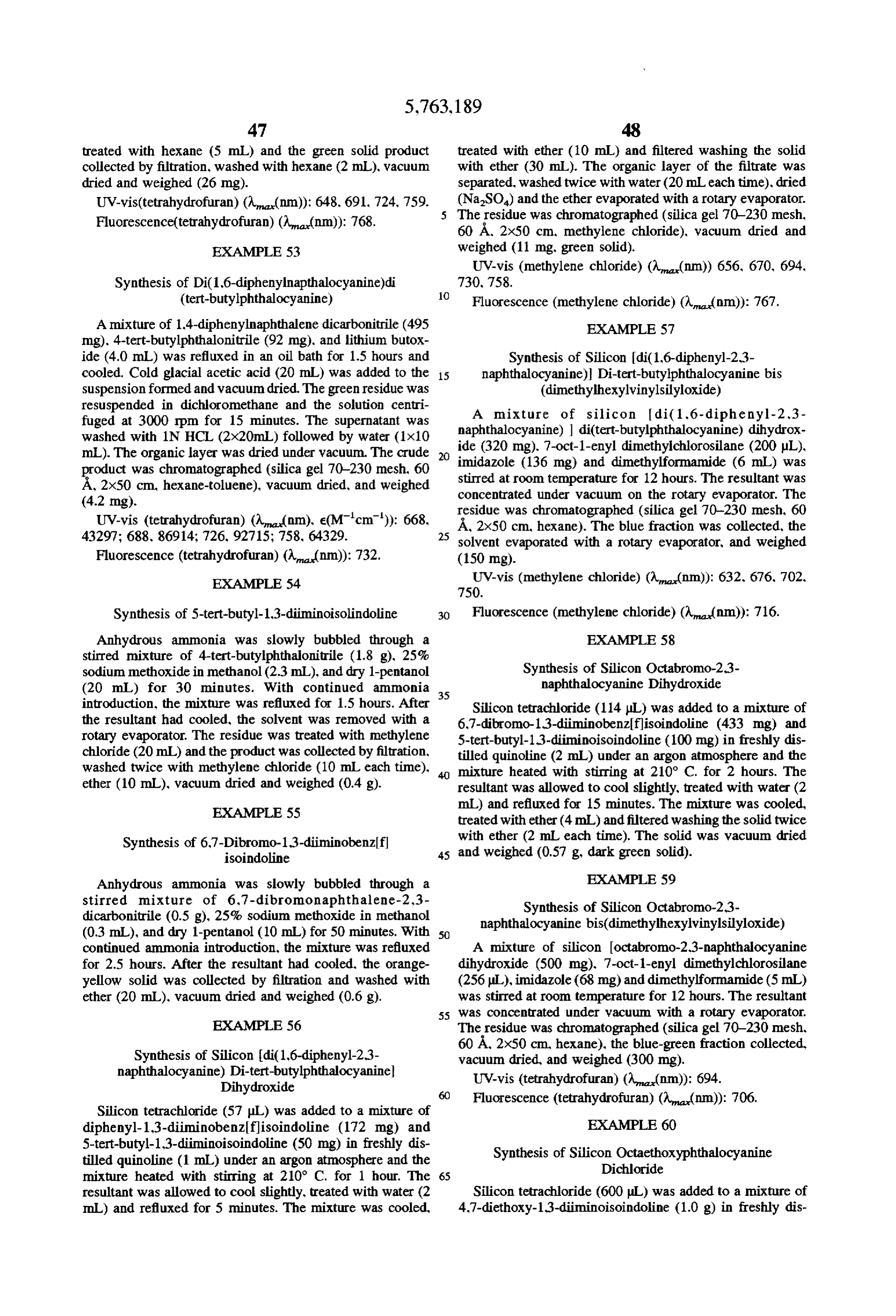
Page 34
tilled quinoline (10 mL) under an argon atmosphere and the EXAMPLE 63 mixture heated with stirring at 200° C. for 1.5 hours. The resultant was allowed to cool and treated with water (10 mL) Synthesis of Germanium tetra-tert and methylene chloride (10 mL). The organic layer was Butylphthalocyanine Dichloride separated and evaporated with a rotary evaporator. The black 5 Germanium tetrachloride (1.5 mL) was added to a mix residue was treated with ether (5 mL) and filtered. The ture of 5-tert-butyl-1,3-diiminoisoindoline (500 mg) and filtrate was dried (NaSO) and the solvent evaporated with tributylamine(3.4 mL) in 1.2.3.4-tetrahydronaphthalene (7 a rotary evaporator. vacuum dried and weighed(300 mg. mL) under an argon atmosphere and the mixture refluxed for dark green solid). 3.5 hours. The resultant was allowed to cool, treated with UV-vis (tetrahydrofuran) ((nm)): 742. 10 water (20 mL) and methylene chloride (20 mL). The organic
UV-vis (methylene chloride) ((nm)): 764. layer was separated, washed with water (10 mL), dried Infrared spectrum (KBr): 3435, 3060, 2983, 2932, 2228. (MgSO) and evaporated with a rotary evaporator. The 1727, 1603, 1504. 1317, 1256, 1218, 1068, 810 cm. residue was chromatographed (silica gel 70-230 mesh. 60
A 2x50 cm, tolueneisopropanol (9:1)), the green fraction
EXAMPLE 61 collected, vacuum dried, and weighed (310 mg).
Synthesis of Diethoxy-1,3-diiminoisoindoline UV-vis (tetrahydrofuran) ((nm)) 680.
Anhydrous ammonia was slowly bubbled through a stirred mixture of 1.4-diethoxy-2,3-phthalonitrile (1.0 g). 20 EXAMPLE 64 25% sodium methoxide in methanol (1.2 mL), and dry Effect of Human Serum on the Fluorescence 1-pentanol (20 mL) for 45 minutes. With continued ammo Intensities of Various Dye Systems in Latex with nia introduction, the mixture was refluxed for 3 hours. After Different Stokes Shifts and Excitation and Emission the resultant had cooled, the solvent was removed with a Wavelengths rotary evaporator. The residue was dried under vacuum and 25 weighed (1.4 g. green solid). Donor and acceptor dye pairs or a hybrid phthalocyanine
EXAMPLE 62
derivative as listed in Table 3 were incorporated into 0.2 micron latex (CML from DC. Portland, Oreg.) using the
Synthesis of Octamethoxy-2,3-naphthalocyanine tetrahydrofuran solvent method. The latex particles were
diluted to various solids concentrations as indicated in the 1,4-dimethoxynaphthalene-2,3-dicarbonitrile (820 mg) Table into either a buffer containing 50 mM potassium suspended in 25% sodium methoxide in methanol (7 mL) phosphate, 10 mM potassium borate, 150 mM sodium was refluxed for 1.5 hours, cooled, and stirred into glacial chloride and 10 mg/mL bovine serum albumin, pH 7 or neat acetic acid (50 mL). After 30 minutes, the solvent was human serum. The excitation and emission wavelengths and evaporated with a rotary evaporator and the residue dis 35 the corresponding Stokes shift are as indicated in the Table. solved in methylene chloride (100 mL). The solution was The results show that the fluorescence intensities mea washed with 10% hydrochloric acid (100 mL), brine (100 sured in neat human serum are greatly affected when the mL) and evaporated with a rotary evaporator. The residue excitation wavelength is in a region where human serum was chromatographed (silica gel 70–230 mesh. 60 A 2x50 absorbs. Conversely, the fluorescence intensities of latex cm, toluene), vacuum dried and weighed (52 mg, red-brown measured in human serum are not affected when the exci solid). tation wavelength is in the region where the serum does not UV-vis (tetrahydrofuran) ( (nm)): 837. significantly absorb.
TABLE 3
Fluores Latex
Dye System Excitation Emission Stokes Cece Solids
(Donord Acceptor) (nm) (nm) Shift intensity (%)
styryl-1-methyl pyridinium
Iodide/Silicon phthalo cyanine bis(dimethylvinyl silyloxide)
Buffer 369.0 0.0019
Serum 28.0 0.0019
porphine/Silicon phthalo cyanine bis(dimethylvinyl silyloxide)
Buffer 2570 0.OOO
Serum 720 O.OOO
indacene Silicon 2,3- naphthalocyanine bis (dimethylhexylvinylsilyl oxide)
Buffer 20.6 0.0005
Serum 19.5 O.OOO5
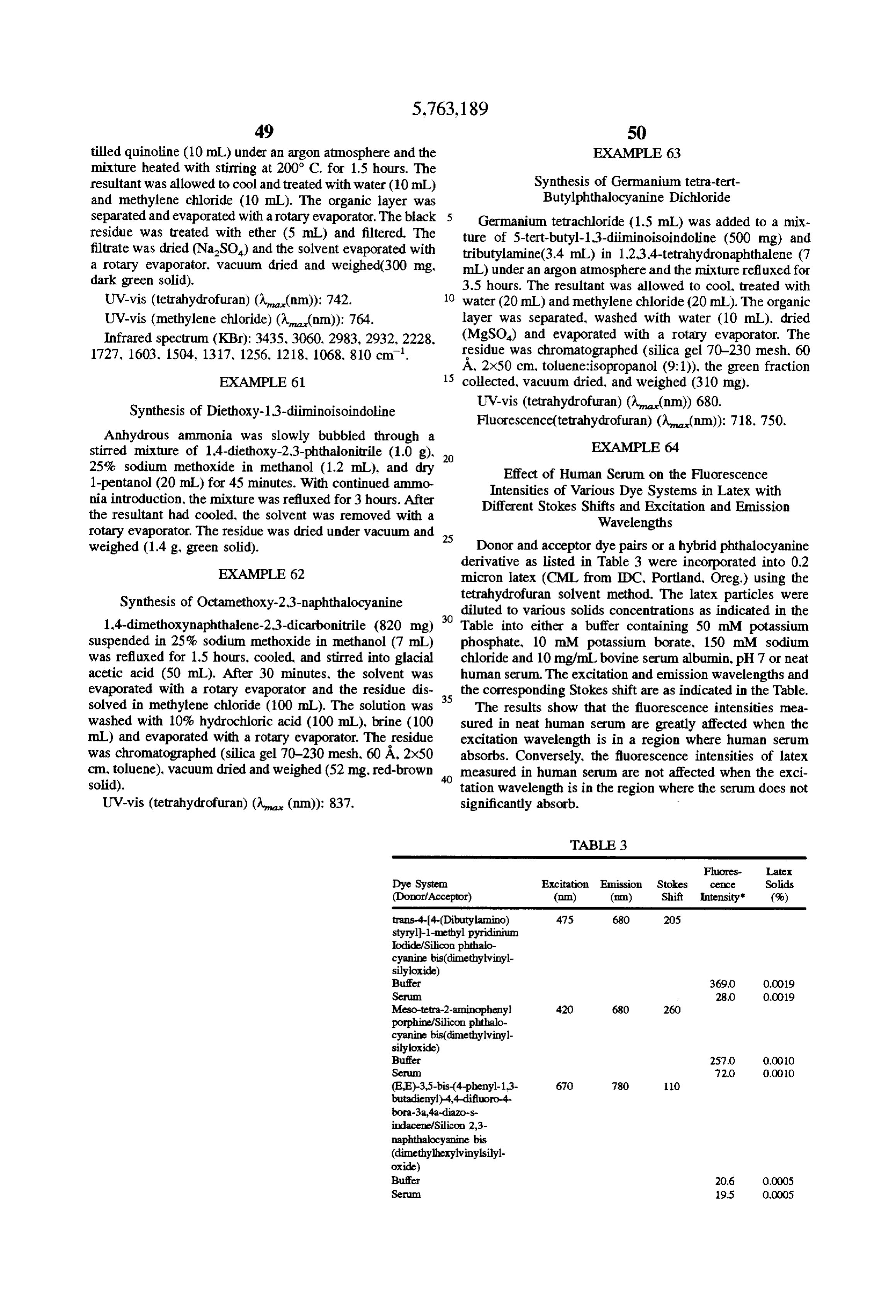
Page 35
S1 S2
TABLE 3-continued
Fluores Latex
Dye System Excitation Emission Stokes CCOce Solids (Donor/Acceptor) (nm) (nm) Shift Intensity" (%) 1.1'-Dihexyl-3,3,3',3'- 650 780 130 tetramethylindodicarbo cyanine Iodide/Silicon 2,3- naphthalocyanine bis (dimethylhexylvinylsilyl oxide)
Serum 30.2 0.0005 Hybrid Compound
Silicon (di(1,6-diphenyl- 646 760 114 naphthalocyanine) diphthalocyanine bis (dimethylhexylvinylsilyl oxide)
*The fluorescence intensities are not corrected.
EXAMPLE 65 EXAMPLE 66
Effect of Axial Ligand on the Quenching of Silicon Comparison of Quenching in Latex for a Hybrid di(1.6-diphenylnaphthalocyanine) Phthalocyanine Derivative and a Naphthalocyanine diphthalocyanines Derivative. Both with Axial Ligands Silicon diC1.6-diphenylnaphthalocyanine) diphthalocya 30 Silicon di(1,6-diphenylnaphthaolcyanine) diphthalocya nine dihydroxide and Silicon di(1,6- diphenylnaphthalocyanine) diphthalocyanine bis nine bis(dimethylhexylvinylsilyloxide (hybrid phthalocya dimethylhexylvinylsilyloxide) were incorporated into 0.2 nine derivative) and silicon 2.3-naphthalocyanine bis dimethylhexylvinylsilyloxide (naphthalocyanine micron CML latex (IDC Corporation, Portland Oreg.) at derivative) were incorporated into 0.2 micron CML latex various dye concentrations as indicated in the Table below 35 (IDC Corporation.
using the THF solvent system. The fluorescent latexes were trations as indicatedPortland in the Oreg.) at various dye concen
Table below using the tetrahy diluted to 0.00057% solids in either 5 mM potassium phosphate, 1 mM potassium borate buffer, pH 7 or in drofuran solvent system. The fluorescent latexes were diluted to 0.00057% solids in either 5 mM potassium tetrahydrofuran. The fluorescence intensities were measured phosphate, 1 mM potassium borate buffer, pH 7 or in by excitation at 646 nm. Emission was set at 760 nm. The tetrahydrofuran. The fluorescence intensities were measured results are presented below in Table 4.
The results show that the dihydroxy hybrid derivative, Table below. emission wavelengths as indicated in the at excitation and which has no axial ligand, has a large degree of quenching, even at 0.1 mg/mL dye loading while the bis dimethylhexy The results show that the hybrid phthalocyanine deriva lvinylsilyloxide hybrid derivative (with the axial ligand) has 45 tive is much more resistant to quenching than the naphtha very little quenching. The results indicate that axial ligands locyanine derivative. The results show the special properties are important for hybrid phthalocyanine derivatives to attain of the hybrid phthalocyanine derivatives for attaining maximum fluorescence intensities in particles. improved fluorescence intensities in latex.
TABLE 4
Fluorescence Percent Quench
Percent Intensity of of Silicon Fluorescence
Quench of Latex con- di(1,6- Intensity of Latex
Silicon taining Silicon diphenyl- containing Silicon di(1,6- di(1,6- naphthalo- di(1,6-diphenyl diphenyl- diphenyl- cyanine) naphthalo naphthalo- naphthalo- diphthalo- cyanine)
Concentration cyanine) cyanine) cyanine bis diphthalo of dye per mL diphthalo- diphthalo- dimethyl- cyanine bis of 2% solid cyanine cyanine hexylvinylsilyl- dimethylhexyl (mg) dihydroxide dihydroxide oxidel vinylsilyloxide 0. 89 O 4.
0.3 80 2 O 10
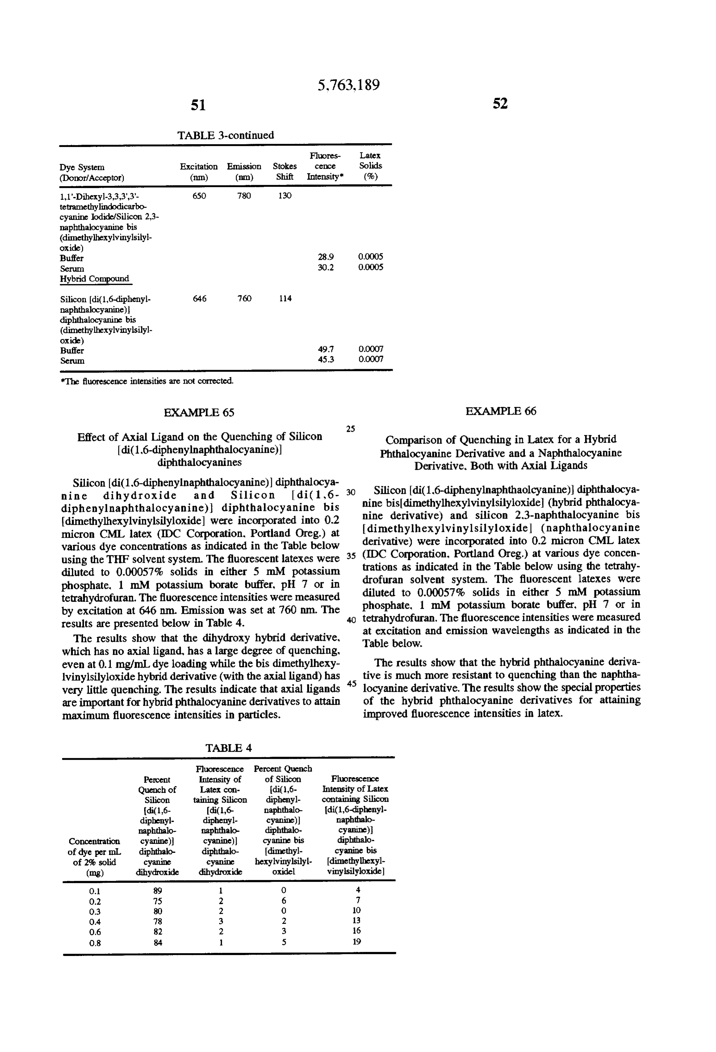
Page 36
electron transfer subunit; and (4) at least one axial
TABLE 5 ligand covalently bound to said metal in said phthalo
cyanine derivative; wherein said derivative(s) is/are naphthalocyanine Fluorescence Quench Fluorescence Quench capable of intramolecular energy transfer from said bis(dimethylhexyl- Intensity of (Ex. 350 Intensity of (Ex. 650 donor subunit to said acceptor subunit; and, vinylsilyloxide) Latex Latex B) randomly incorporating said phthalocyanine derivative concentration (Ex. 350 nm Em. 780 (Ex. 650 m Em 780 (s) into a microparticle selected from the group con
sisting of latex, silica, alumina, liposomes and colloids.
O. 11 O 15 2. A loadable microparticle comprising a fluorescent O.3 34 13 3 30 O phthalocyanine derivative having a metal with at least one
O.7 63 26 6 41 axial ligand covalently bound to said metal in said phtha O.9 31 32 3. 46 locyanine derivative.
3. A loadable microparticle comprising a fluorescent hybrid phthalocyanine derivative having a metal with at 15 least one axial ligand covalently bound to said metal in said
Silicon di(16 diphenylnaphtha hybrid phthalocyanine derivative. locyanine) Percent Percent 4. A fluorescent microparticle made by the process com diphthalocyanine Fluorescence Quench Fluorescence Quench prising: A) selecting a series of fluorescent dyes comprising bisdimethyl- Intensity of (Ex. 350 Intensity of (Ex. 650 hexylvinylsilyl- Latex Latex at least one initial donor dye with a desired excitation peak
of greater than approximately 500 nm and two or more final
tion (mg/mL) Eml 760 nm) nnn) Em. 760 m) m) acceptor dyes with desired emission peaks equal to or very 0.1 11 O 6 O similar to each other, wherein each dye in the series has a 0.3 31 O 16 O spectral overlap sufficient to allow for significant energy O5 56 O 28 O transfer of excitation energy to the final acceptor dyes and O.7 60 O 30 O 25 wherein a Stokes shift of treater than or equal to 50 nm exists
between the energy donor and at least one of the energy 2.0 13 O 58 3 acceptors, and at least one of said acceptor dyes has an emission wavelength greater than approximately 680 nm, and B) randomly incorporating said series of dyes in a
We claim: 30 microparticle, whereby the improved particle exhibits mini 1. A composition made by a process comprising steps of: mal fluorescence quenching and maximum fluorescence A) selecting at least one fluorescent hybrid phthalocya intensity.
nine derivative containing a metal, said derivative(s) 5. The microparticle of claim 4 wherein said emission having (1) at least one donor subunit with a desired peaks are within 10 nm of each other.
excitation peak; and (2) at least one acceptor subunit 35 with a desired emission peak; and (3) at least one k :
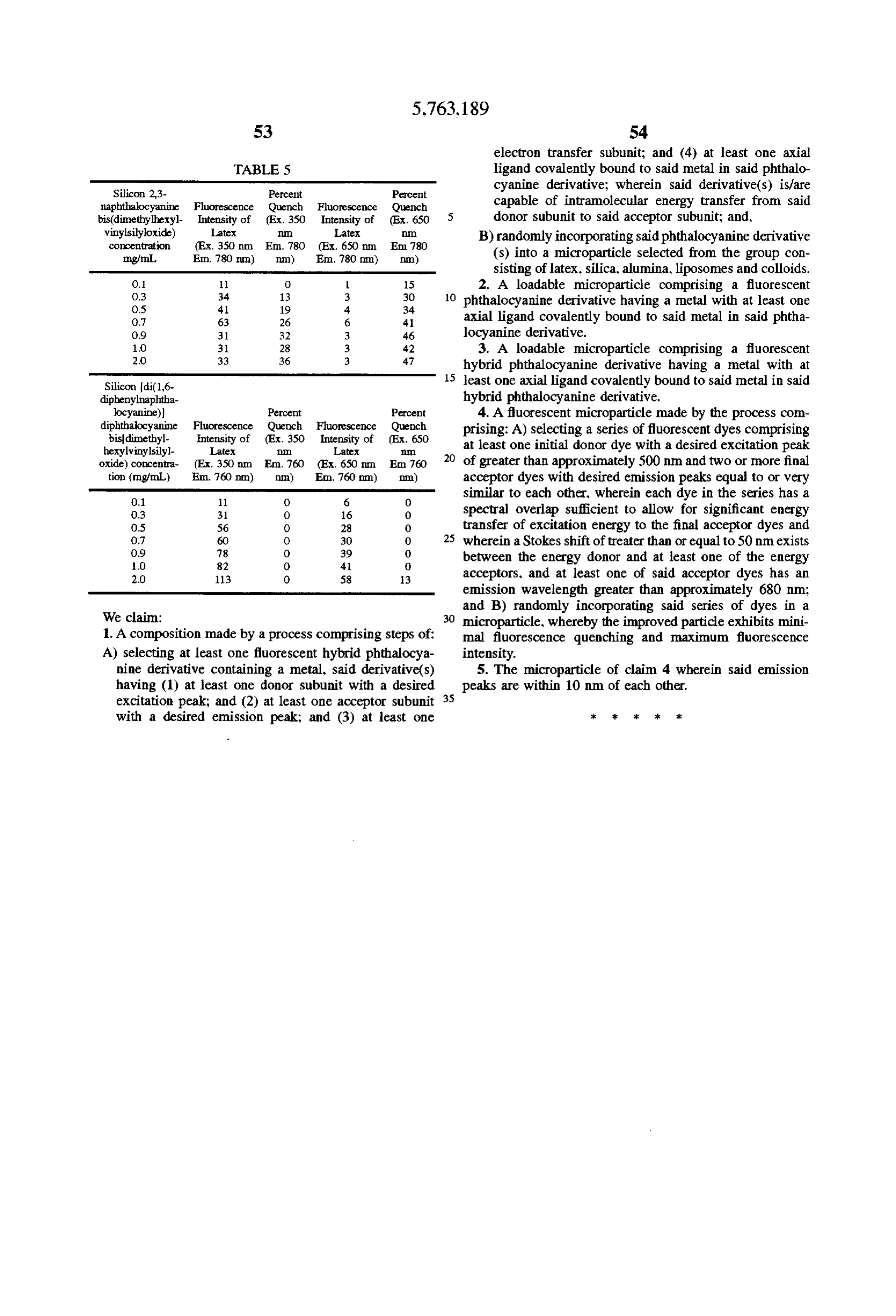
Provenance
- Collection
- Cited prior art
- Original PDF
- patentimages.storage.googleapis.com →
- Filed
- 1994-09-23
- Pages
- 36
- Method
- pdftotext (the PDF's own text layer) + pdftoppm 300dpi page scans
- Source
- Google Patents bibliographic record
- Granted
- 1998-06-09
- Inventors
- Kenneth F. Buechler; J. Barry Noar; Lema Tadesse; Biosite Diagnostics Inc
- Transcribed from
- patentimages.storage.googleapis.com →