patent · US5593509
Portable thermo-photovoltaic power source
14 January 1997
Page 1 — bibliographic record
IIII
United States Patent 19 11 Patent Number: 5,593.509 Zuppero et al. 45) Date of Patent: Jan. 14, 1997 54 PORTABLE THERMO-PHOTOVOLTAIC Primary Examiner–Aaron Weisstuch POWER SOURCE Attorney, Agent, or Firm–Thorpe North & Western 75 Inventors: Anthony C. Zuppero; Barton
Krawetz, C. Rodger Barklund; Gary 57 ABSTRACT
D. Seifert, all of Idaho Falls, Id.
A miniature thermo-photovoltaic (TPV) device for genera 73) Assignee: Lockheed Idaho Technologies tion of electrical power for use in portable electronic Company, Idaho Falls, Id. devices. A TPV power source is constructed to provide a heat source chemical reactor capable of using various fuels, (21 Appl. No.: 406,236 such as liquid hydrocarbons, including but not limited to propane, LPG, butane, alcohols, oils and diesel fuels to 22 Filed: Mar 17, 1995 generate a source of photons. A reflector dish guides mis directed photon energy from the photon source toward a (51) Int. Cl. ................................................ HOL 31/O58 photovoltaic array. A thin transparent protector sheet is 52 U.S. Cl. ............................................................. 136/253 disposed between the photon source and the array to reflect (58) Field of Search ............................................... 36/253 back thermal energy that cannot be converted to electricity, and protect the array from thermal damage. A microlens 56 References Cited disposed between the protector sheet and the array further
source onto an array of photovoltaic cells, whereby the 4,331,829 5/1982 Palazzetti et al. ...................... 136,253 photon energy is converted to electrical power. A heat 4,584,426 4/1986 Nelson ................. ... 136,253 recuperator removes thermal energy from reactor chamber 4,707,560 1/1987 Hotel et al. ......... 36/253 exhaust gases, preferably using mini- or micro-bellows to 4,883,619 171989 Diederich et al. ........................ 264f60 force air and fuel past the exhaust gases, and uses the energy 4,975,044 12/1990 Diederich ......... ... 4311110 5,057, 62 10/1991 Nelson ......... ... 136,253 to preheat the fuel and oxidant before it reaches the reactor, 5,312,521 5/1994 Fraas et al. ...... 136.253 increasing system efficiency. Mini- or micro-bellows force 5,356,487 10/1994 Goldstein et al. ... 1367253 ambient air through the system both to supply oxidant and 5,360,490 1 1/1994 Nelson .................................... 36/253 to provide cooling. Finally, an insulator, which is preferably 5,383,976 1/1995 Fraas et al. ............................. 36,253 a super insulator, is disposed around the TPV power source OTHER PUBLICATIONS to reduce fuel consumption, and to keep the TPV power source cool to the touch so it can be used in hand-held
International Solar Energy Intelligence Report, Jul. 11, devices.
Mechanical Engineering-CIME, Sep.1994.
"Developing New Miniature Energy Systems' Mechanical
Engineering-CIME, vol. 116, No. 9, p. 82 (1994). 51 Claims, 10 Drawing Sheets
Page 2
Drawing sheet — no readable text.
Page 3
hot fuel in hot air in Starter mechanism 280 heat SOUrCe
Chemical reactor 21 O
hot exhaust out heat in Contact with
Converter 230 light in band of PV photo voltaic
(PV) element 240
electricity out
Figure 4:
Page 4
Drawing sheet — no readable text.
Page 5
Drawing sheet — no readable text.
Page 6
Drawing sheet — no readable text.
Page 7
Drawing sheet — no readable text.
Page 8
Fuel Tank
Heat Management Hot Exhaust System 270 COO Exhaust
Hot Fuel and Air Out
POWer Chamber
Electricity out POWer
Conditioning 550 Electricity
Power Storage
Electricity,
On-demand Out
Figure 10
Page 9
Drawing sheet — no readable text.
Page 10
Drawing sheet — no readable text.
Page 11
Drawing sheet — no readable text.
Page 12
PORTABLE THERMO-PHOTOVOLTAC ductive, especially when the batteries must be returned to a POWER SOURCE home site for charging. Adding to the problem is the cost of equipment necessary for recharging. Furthermore, the shelf
CONTRACTUAL ORIGIN OF THE INVENTION life of batteries is also only a matter of years, and batteries can lose their charge while waiting to be sold. Another
The United States Government has rights in this invention realistic concern these days is the environmental impact of disclosed under contract number DE-AC07-94ID 13223 with disposed batteries and the corrosive elements that leak Lockheed Idaho Technologies Company. during decomposition.
Attempts have been made to provide more efficient por
BACKGROUND OF THE INVENTION 10 table power sources that do not suffer from all the drawbacks
1. Field of the Invention of batteries. Most of the attempts have focused on improving features of batteries themselves, such as substituting the
This invention pertains to a small and portable power chemicals storing energy. Other alternative power sources source, and specifically pertains to a thermophotovoltaic have been developed for commercial use, but have not been power source that generates heat bringing an emissive 15 miniaturized to replace batteries because of technological spectrum converter to incandescence and thereby producing barriers that have, until now, prevented this action. Such a light in a narrow wavelength spectrum to which nearby power source is thermophotovoltaic (TPV) technology. photovoltaic cells are particularly sensitive, generating elec TPV power is generated by elevating a radiant emitter to tricity to power portable and hand-held devices which incandescent temperatures. The radiant energy is captured require significant amounts of energy but are presently 20 on semiconductor photovoltaic converter arrays (solar cells) limited in use because of the low energy densities provided and converted directly into electrical power to be stored or by conventional power sources. used immediately. While this principle of operation sounds There are a variety of civilian and military situations simple enough in macro applications, the problems of min which would benefit from a portable power source that can iaturization have prevented anyone, as far as the inventors of supply larger amounts of energy over extended periods of the present invention are aware, of developing and success time than conventional batteries. Electronic surveillance fully implementing a miniaturized TPV power source. systems, robotics, communications and computing devices For example, up to the present time, TPV devices have all have very limited periods of usefulness when they are been limited exclusively to macro-applications. That is, the mobile or must necessarily be disconnected from power grid size of the TPV power sources has been relatively large. connections. A power source capable of delivering higher 30 TPV power sources have been proposed for such tasks as energy densities would not only provide extended life for the generating energy to be stored for household purposes. A systems above, but would enable other devices requiring TPV device could be used to providelighting and heat water, higher input energies to operate remotely. and the electrical energy produced as a by-product of the 2. Prior Art process could be stored in batteries and accessed for use by
Our increasing abilities to make use of electronics tech household appliances such as a heating fan. nology has created a need for being mobile with our tech The basic elements of a TPV power source have largely nological devices. As technology advances, these devices but not exclusively consisted of what will be referred to as become capable of accomplishing more tasks. However, a power chamber. A power chamber comprises a heat source portable devices have limited use because conventional reactor, an emissive spectrum converter (ESC), a photovol batteries quickly lose their charge. Furthermore, our mobil taic element (PV) and a starter means. Some TPV power society has only increased our desire to be able to handle any sources have proposed the use of heat recuperators. task requiring technology, no matter where we are. Conse A further description of the workings of TPV power quently, devices are developed to provide remote location generation is helpful in understanding the prior art, and capabilities that can rival those of a home or office. Never 45 provides a basis for understanding the present invention. A theless, with increased capability comes the inevitable heat source reactor is any heat source capable of generating increase in power requirements. Unfortunately, portable sufficient heat to bring to incandescence a narrow band power for devices such as cellular phones, notebook com thermal emitter. A thermal emitter, or emissive spectrum puters, power tools, toys, medical equipment, radios, pager, converter, when glowing hot will ideally be constructed to backup power supplies and robotic applications has always 50 emit the majority of light in a narrow band, thus converting meant batteries. Batteries come in many shapes and sizes, heat energy to light energy in a narrow spectrum. This is but share several characteristics which limit their use. useful because the radiation is directed to a semiconductor For example, alkaline, nickel-cadmium and nickel-metal photovoltaic material such as silicon. A semiconductor with hydride batteries commonly used in the above mentioned a pnjunction creating a potential barrier gives rise to a band devices all depend upon chemical energy being converted 55 gap that is a function of the material used. Silicon, with a into electrical potential energy. The energy density of these band gap in electron volts of about 1.1 eV is equivalent to batteries is low so as to prevent or limit the explosive a wavelength of about 1150 nanometers. The more radiation discharge of energy if the battery cells should be ruptured, that can be focused on the photovoltaic material with energy compressed or heated. Although it is possible to create better of 1.1 eV, the more electricity the photovoltaic material will batteries, tests show that batteries with an energy density 60 produce. Of course, not all the heat energy will be usefully similar to that of explosives tend to act like high explosives transferred to the photovoltaic material. This excess energy when mistreated. is lost as heat and in photons aimed away from the PV cells. Low energy density translates into a battery providing a An efficient TPV power source will capture excess heat in a small amount of power over a relatively short time period for recuperator and use this energy to precondition air acting as the user. But there are other drawbacks to conventional 65 an oxidant and the fuel being fed to the heat source reactor. batteries as well. Even if the battery can be recharged, the Addressing specific embodiments of TPV technology, time it takes to recharge is probably time lost being unpro several U.S. Patents describe the major areas of advance
Page 13
ment to date. For example, U.S. Pat. No. 4,584,426 teaches It is also an object of the present invention to provide a how "blackbody' radiation sources, such as the sun, are heat source chemical reactor that can produce temperatures inefficient for producing the particular wavelength of light sufficient to cause emissive spectrum converter incandes required by silicon photovoltaic power cells to produce cence, and yet safely be held in a hand. electricity because the sun is a broadband radiation emitter. It is another object to provide a TPV power source with The patent teaches how a gas mantle can be prepared with efficiency of at least 10 percent. a rare earth oxide such that when heated to incandescence, It is still another object to provide a heat source chemical the mantle not only produces the majority of its light in a reactor that can generate heat from a variety of alcohols, oils narrow band wavelength, but the spectrum is centered or diesel fuels.
around that wavelength which is necessary for optimal 10 It is yet another object to provide a heat source chemical production of electricity by silicon photovoltaic cells. The reactor that is surrounded by a super insulator such that the patent is typical of the macro-technology to which TPV TPV power source can be safely used in a hand-held device. technology has been applied. It is still another object of the present invention to Another example of TPV technology is the recuperator construct a miniaturized heat source chemical reactor shown in U.S. Pat. No. 4,707,560 which teaches how 15 capable of providing 30 watts of thermal power. preheat of the oxidant (air) can reduce the flame temperature It is also an object of the present invention to provide a required to heat the emissive spectrum converter. This miniature TPV power source that has a virtually infinite makes the TPV device more efficient and slows the rate of shelf life.
fuel consumption. It is still another object of the present invention to provide Many improvements of macro TPV technology have 20 aheat recuperator that uses air to cool exhaust gases and will concentrated on making a better gas mantle which is impreg preheat air for insertion in the heat source reactor chamber. nated or coated with the rare earth oxides, such as U.S. Pat. It is a further object to provide a system of micro-lensing Nos. 4,883,619, 4,975,044, and 5,057,162. Another macro to focus and channel usable light from the ESC to a improvement includes a ceramic fiber matrix heat source 25 photovoltaic cell.
and emissive spectrum converter as taught by U.S. Pat. Nos. It is yet a further object of the present invention to use 5,356,487 and 5,360,490. diamond film coatings, or their thermally conducting The overriding commonality between all of the patents equivalents, to transfer exhaust gas heat energy to cold fuel described, and all others found by the inventors, is that TPV and air to improve efficiency of the power source. power sources are macro devices. That is to say that the 30 Another object of the present invention is to construct physical dimensions of the components that comprise the multiple TPV devices on application specific integrated power chamber are relatively large because the applications circuits (ASICs) such that power output may be controlled for which they were designed are household appliances such when energy requirements of the power change. as hot water heaters and household electric power genera tors. The substantial technological problems of adapting Yet another object of the present invention is a TPV TPV technology to micro-technology have until now pre 35 device power source that can produce at least 3 watts of cluded such adaptation. electrical power.
What is needed is a way to provide portable power that It is finally another object of the present invention to has the lower energy density and safety of oil, but effective provide an air transport means for pushing or pulling air energy density greater than high explosives. The higher 40 through the TPV system.
energy density would result not only in higher power output, These and other objects not specifically recited are real but power output sustained over a longer period of time. In ized in a specific illustrative embodiment of a miniature addition, a longer and preferably infinite shelf-life would thermophotovoltaic device for generation of electrical result in less waste of resources, further reducing the impact power for use in portable electronic and mechanical devices. of portable power use on the environment. Virtually instan 45 In a preferred embodiment, a TPV power supply is con taneous recharging of the power source would also be a structed of miniaturized components to provide a heat definite advantage, as well as the elimination of equipment source chemical reactor capable of using various alcohols, necessary for recharging. The power source should be oils and diesel fuels to generate heat sufficient to bring an compact and lightweight to replace batteries, and yet be ESC coating to a burner to incandescence. A reflector dish rugged devices that would not suffer from the potential 50 cupping the burner redirects photon energy toward the problems of high energy density power sources if mis photovoltaic array. A micro-lens focuses the narrow band handled. Finally, a wider range of fuel sources should be light from the ESC on an array of photovoltaic cells, useable with the TPV power source. whereby the photon energy is converted to electrical power. As the above situations imply, it would also be an The photovoltaic cells are protected from the heat energy of advantage over the prior art TPV power sources if the 55 the ESC by a thin diamond coated transparent boundary elements of the power chamber were miniaturized and which feeds excess heat energy back to a heat recuperator. ruggedized. It would also be an improvement over conven The heat recuperator uses the excess heat energy to preheat tional batteries if a TPV power source could replace them the reactor oxidant and fuel, thereby increasing system without requiring more space than is currently occupied by efficiency.
the batteries, thus eliminating the cost of retrofitting portable 60 Substantial advancements in microgears, micropumps devices for TPV power, and yet provide substantially greater and micro heat transfer devices enable the preheated fuel energy that will last for a longer period of time. and air to be forced at some positive overpressure into the OBJECTS AND SUMMARY OF THE heat source reactor while excess heat energy from their INVENTION combustion is fed back into the reactor chamber.
65 Also disclosed is a method for power load following using
It is an object of the present invention to provide a a series of TPV power sources, which includes the steps of miniaturized thermophotovoltaic device. (i) providing a plurality of TPV devices and/or on a planar
Page 14
S 6
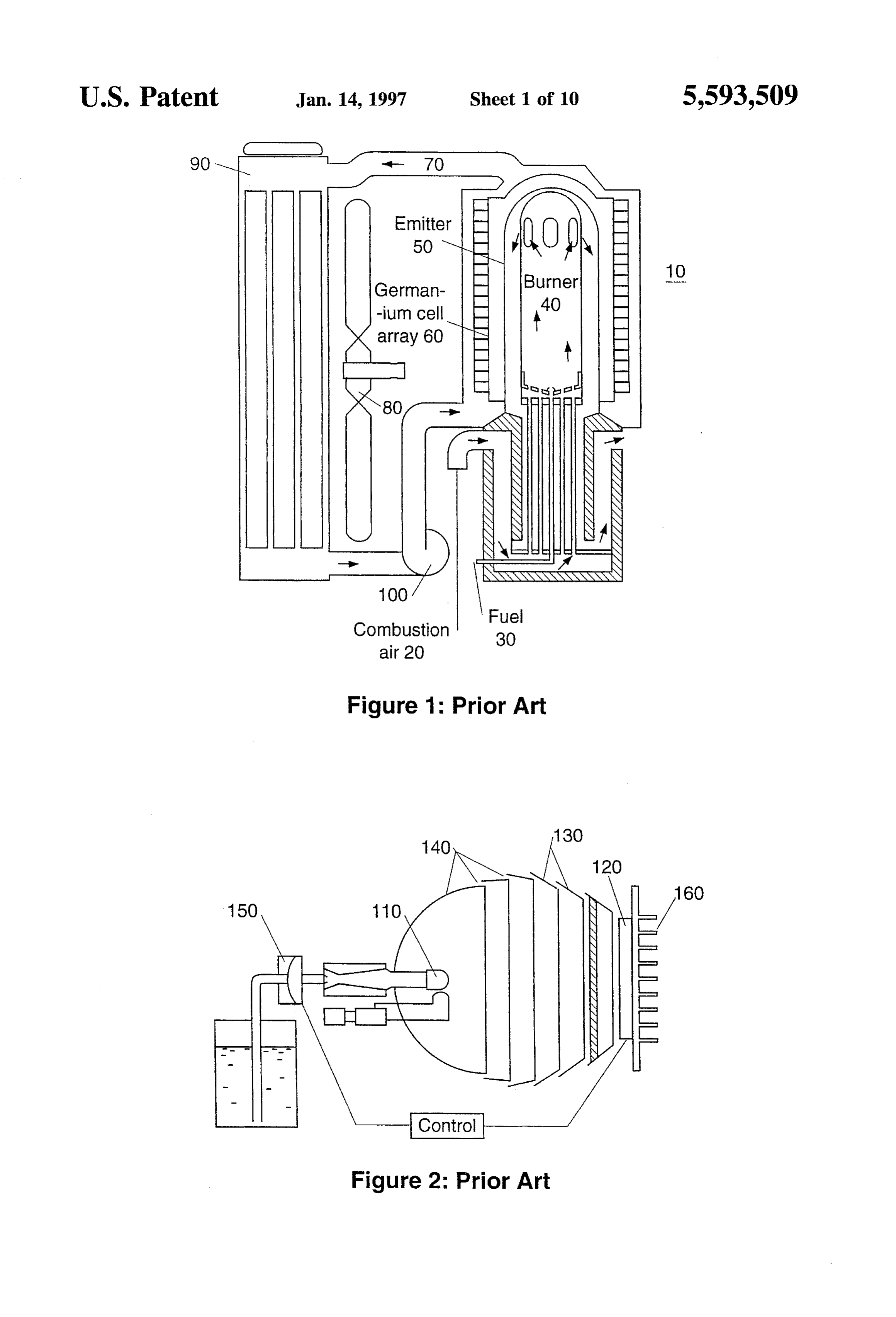
ASIC device, (ii) linking the TPV devices such that power view illustrates the flow path of combustion air 20 and fuel output is the cumulative power output of each separate TPV 30 into a combustion chamber and burner 40. Surrounding device, and (iii) providing additional circuitry on the ASIC but not in contact with the burner is an emitter 50 that is device to enable shutdown or reactivation of individual TPV heated to incandescence. Surrounding the emitter 50 is an devices depending upon the power load requirements. array of germanium photovoltaic cells 60 that generate DESCRIPTION OF THE DRAWINGS electricity from the light produced from the incandescent emitter 50. A coolant fluid 70 flows around the photovoltaic
The above and other objects, features, advantages and cells 60 to prevent the excess heat not converted to elec alternative aspects of the invention will become apparent tricity by the cells 60 from damaging the array. from a consideration of the following detailed description O What should be noted about the TPV power chamber presented in connection with the accompanying drawings in (heat source reactor chamber and burner 40, emitter 50, which:
FIG. 1 is an elevational cut-away view of a TPV generator photocells 60, cooling mechanism 70) is that the device shown is relatively large, and suitable for generating electric as used in macro TPV power sources of the prior art. power in the range of 1000 watts. Such a design is unsuitable FIG. 2 is an elevational cut-away view of a more 15 for use in the present invention for many reasons. For advanced adaptation on the TPV generator of FIG. 1, example, the coolant system 70 is bulky, requiring a fan 80 showing that the burner and emitter have been combined as for cooling the radiator 90 through which coolant 70 flows, a gas mantle. and a pump 100 for keeping the coolant 70 flowing. Such a FIG. 3 is a block diagram of the elements of a TPV power design cannot be implemented for use in a portable or chamber made in accordance with a preferred embodiment 20 hand-held device.
of the present invention. FIG. 2 shows some improvements to the TPV power FIG. 4 is a flowchart of the basic operation of a thermo generation system of FIG. 1. One improvement is that the photovoltaic power chamber showing the inputs and outputs heat source reactor 110 has been reduced in size to a gas to the system described in FIG. 3. mantle. The mantle 110 is impregnated with a rare earth FIG. 5A is an elevational cross-section view of a TPV 25 oxide radiator that when heated to incandescence provides a power chamber made in accordance with a preferred narrow spectrum radiation source. The light is focused on a embodiment of the present invention. photovoltaic array 120 by an aluminum reflector array 130 FIG. 5B is an alternate embodiment showing a cross with air vents 140.
section of a reflector dish added to the burner.
Unfortunately, this device cannot be significantly minia
FIG. SC is an alternate embodiment showing a cross 30 turized nor used in a hand-held device. Gas mantle technol section of a microlens added between the protector sheet and ogy will not work because of the difficulty in creating a photovoltaic array. mantle that can withstand even mild stresses. While a FIG. 6A is a cross-section perspective view of a heat process has been proposed to make gas mantles less sus recuperator in a preferred embodiment as would be incor ceptible to damage, the dimensions of gaps in the weave of porated in FIG. 5A, with FIG. 6B showing a top view of 35 current mantles is a significant fraction of the size of the total
FIG. 6A.
TPV device as envisioned. Furthermore, the macro TPV
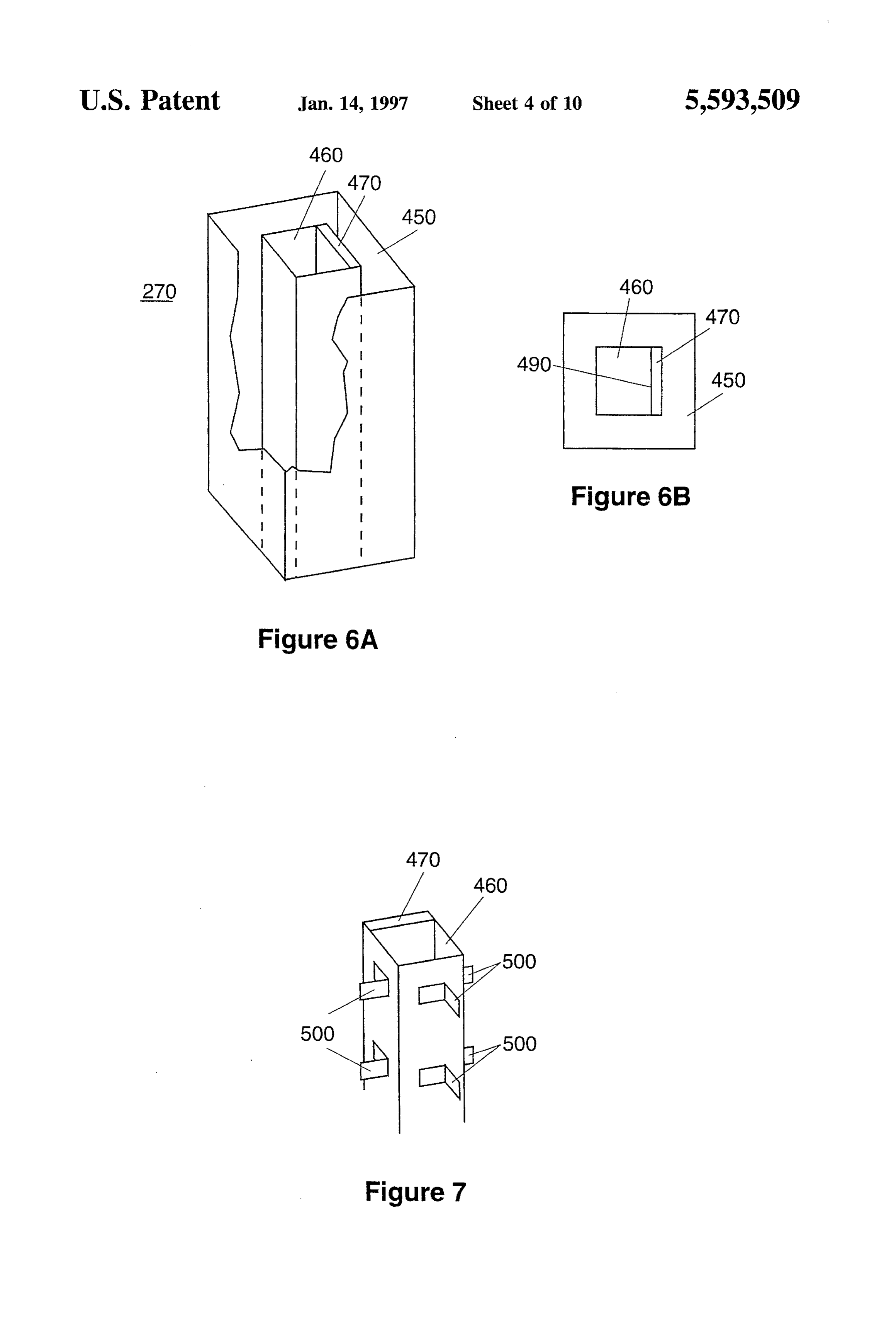
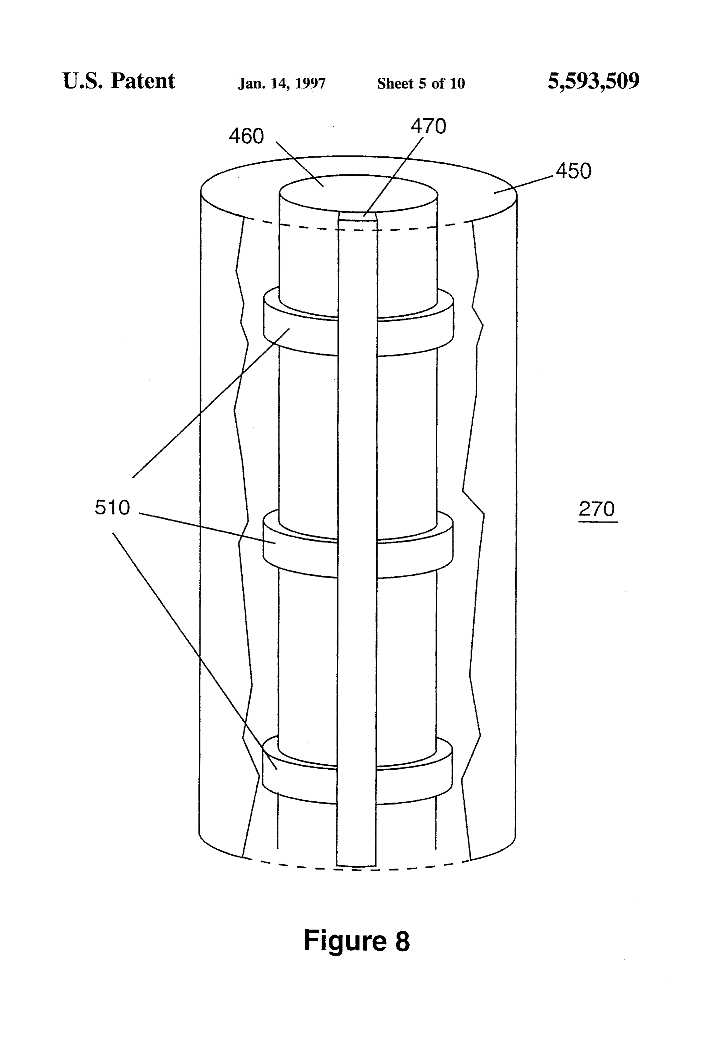
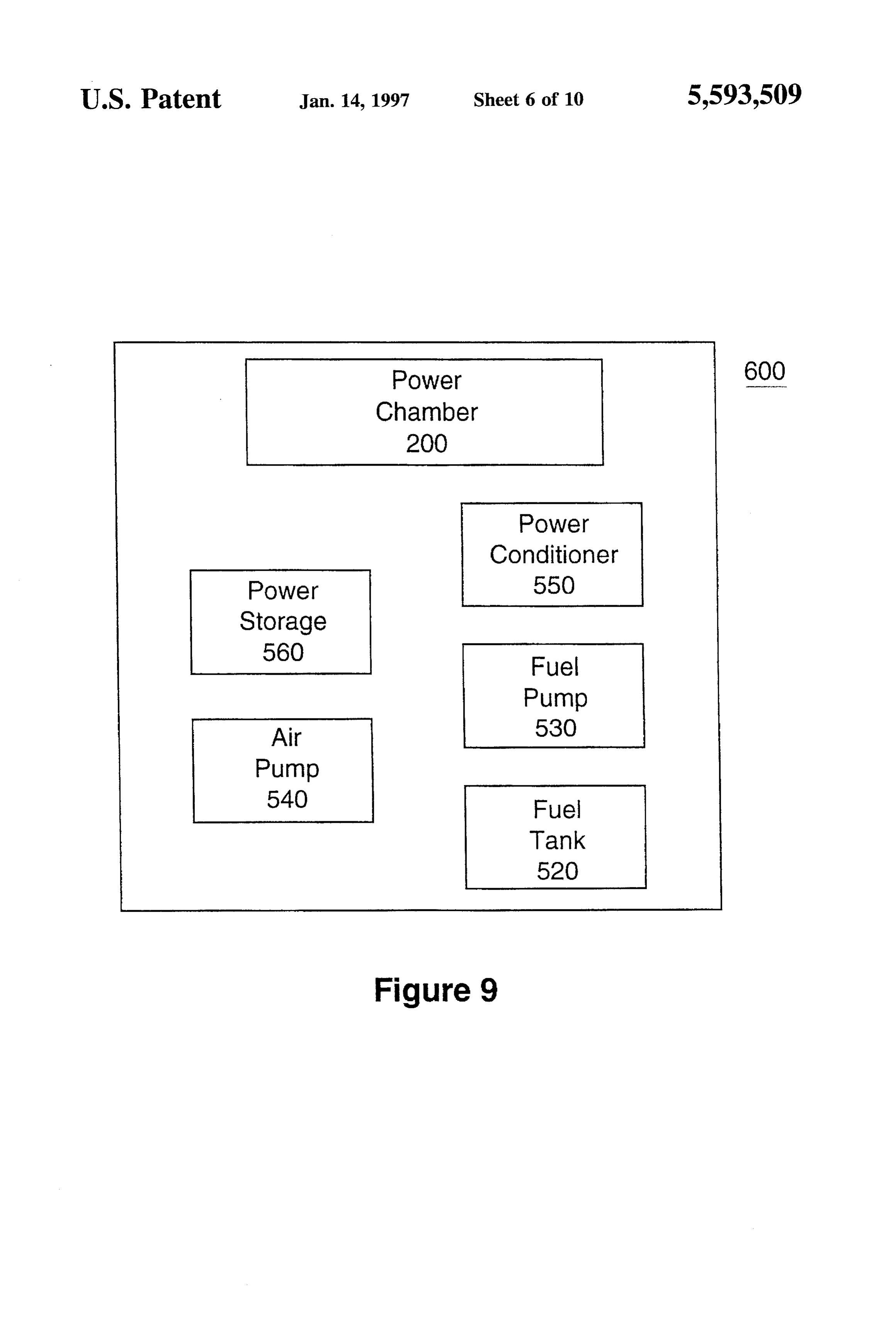
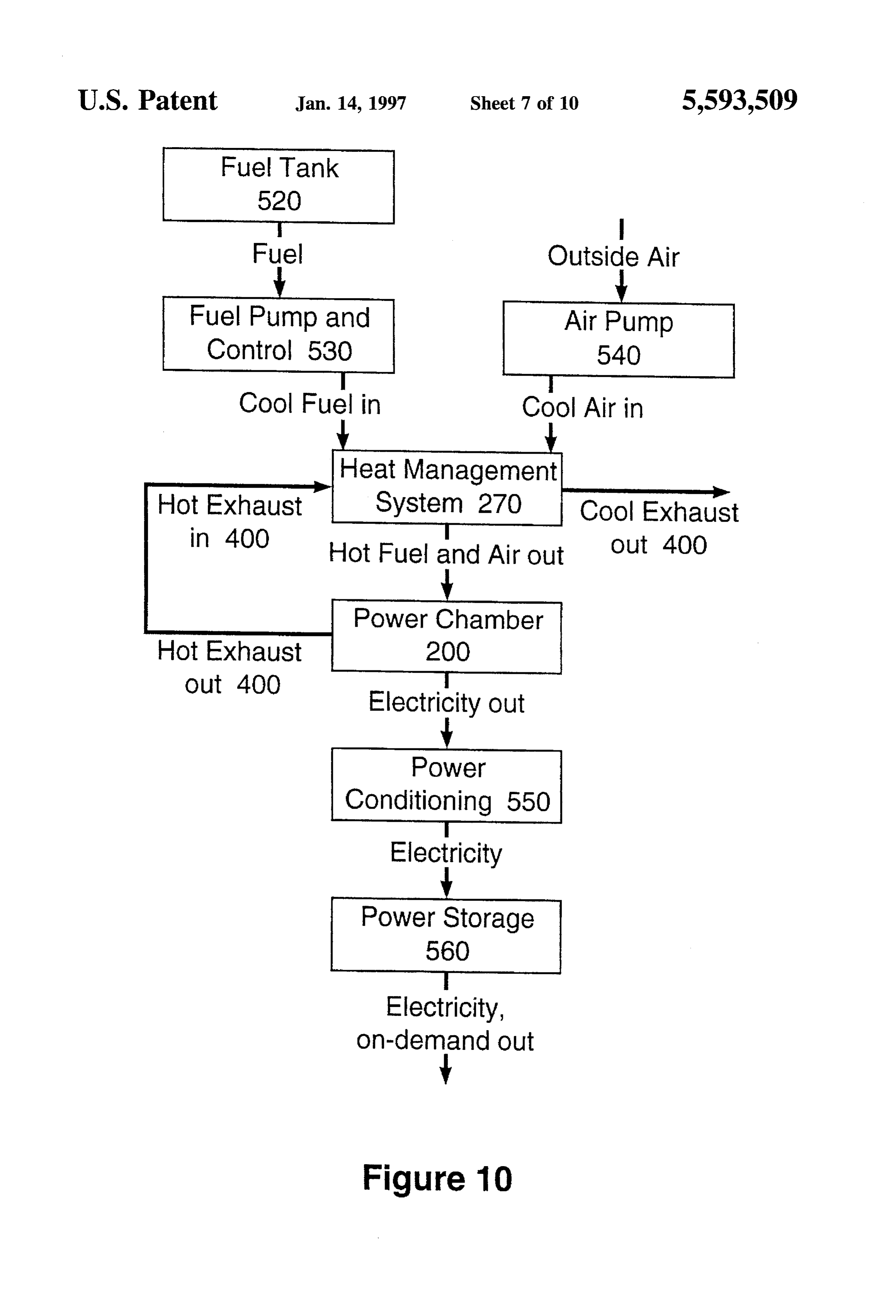
FIG. 7 is a cross-section perspective view of an alternative device generates significant heat, yet lacks substantial insu embodiment of a heat recuperator of FIG. 6. lation, making it difficult to touch these prior art devices. FIG. 8 is an elevational cross-section view of another Just as problematic is the lack of a means for forcing an alternative embodiment of the heat recuperator of FIG. 6. 40 oxidizer into the combustion chamber. A macro device does FIG.9 is a block diagram of the additional components in not require such an apparatus because natural airflow a complete TPV power generation system. through vents is usually sufficient. The use of ordinary fuel FIG. 10 is a flowchart of the basic operations of the TPV pumps 150 is also sufficient for macro devices, but unwork power source showing the system described in FIG. 9. 45 able in a miniaturized TPV power system. Likewise, meth
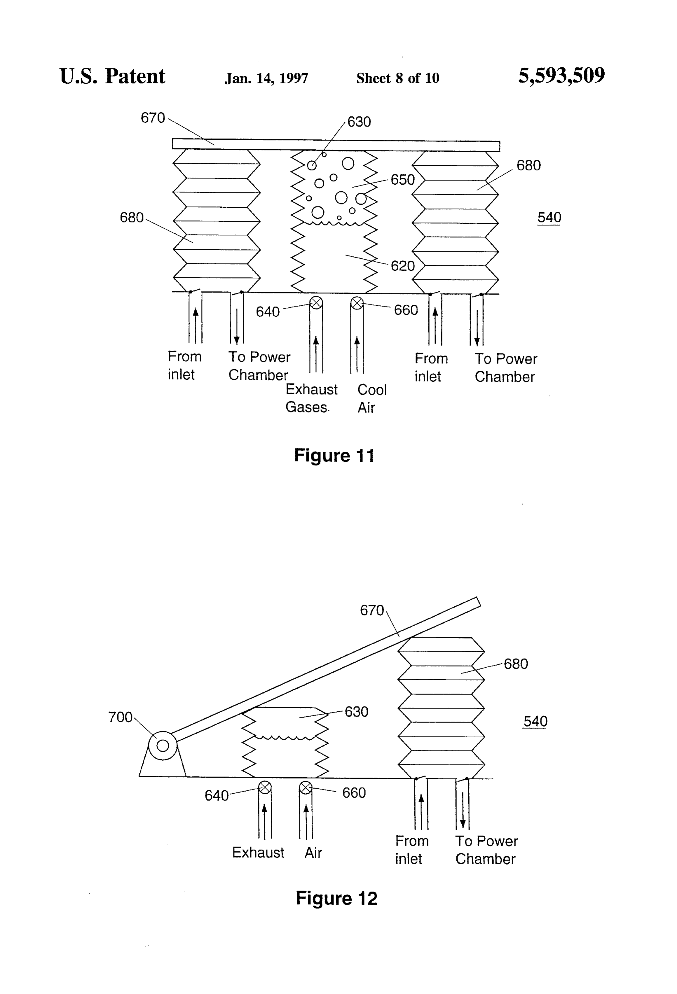
FIG. 11 is an elevational cross-section view of an air ods of protecting the photocells such as heat sinks 160 are pump for moving air to the heat source chemical reactor of inadequate in a miniaturized system because of the short FIG. 3. distances between components.
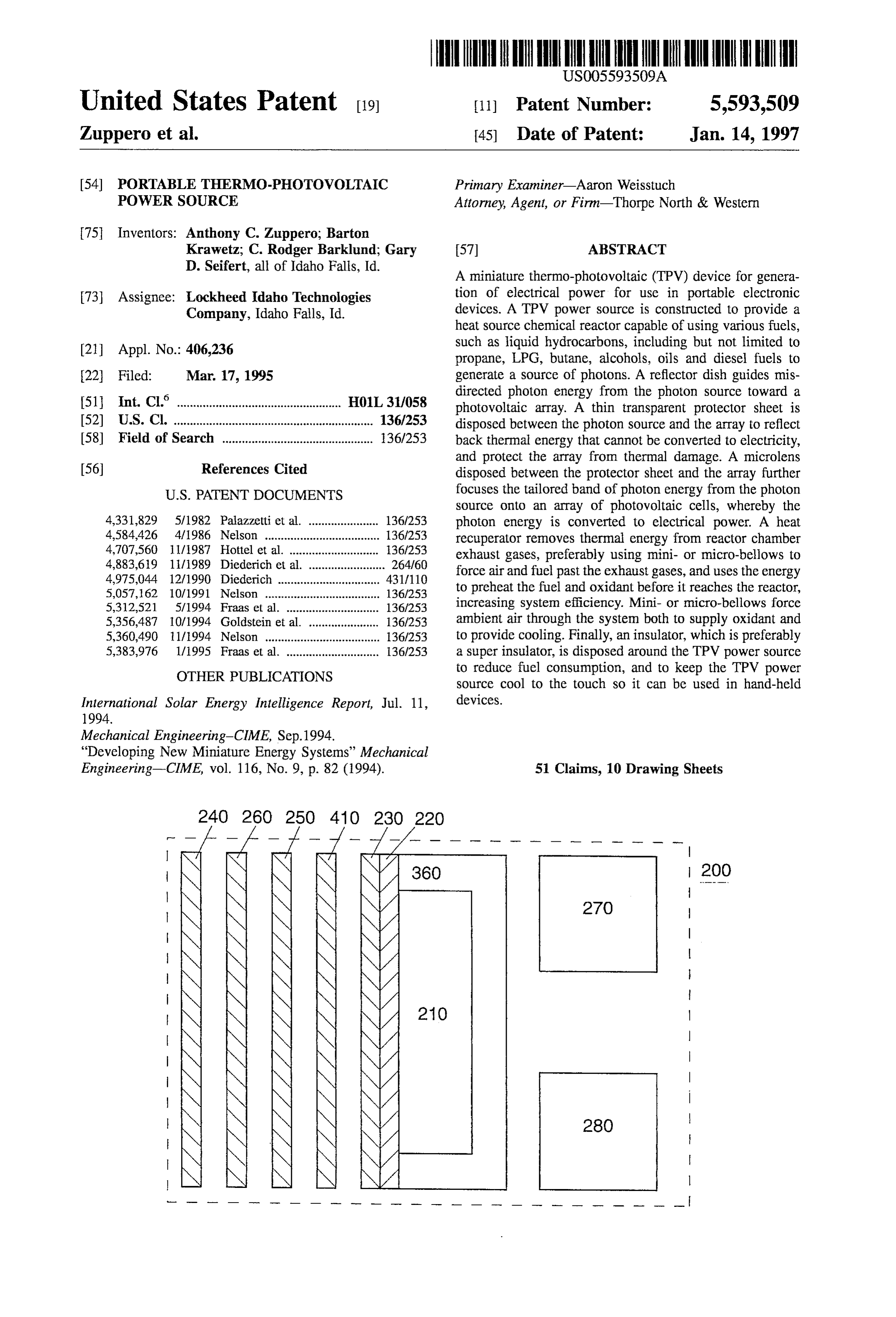
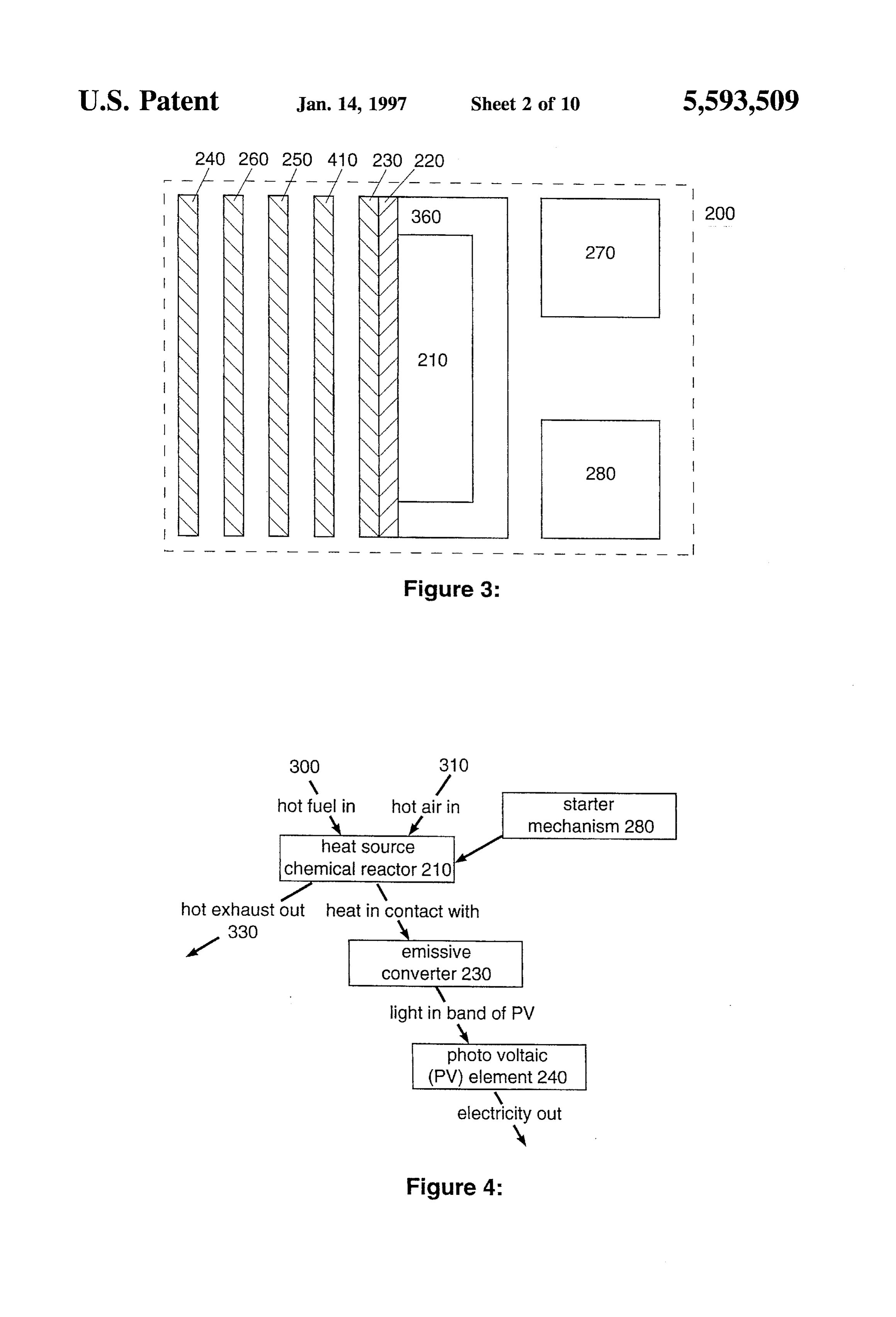
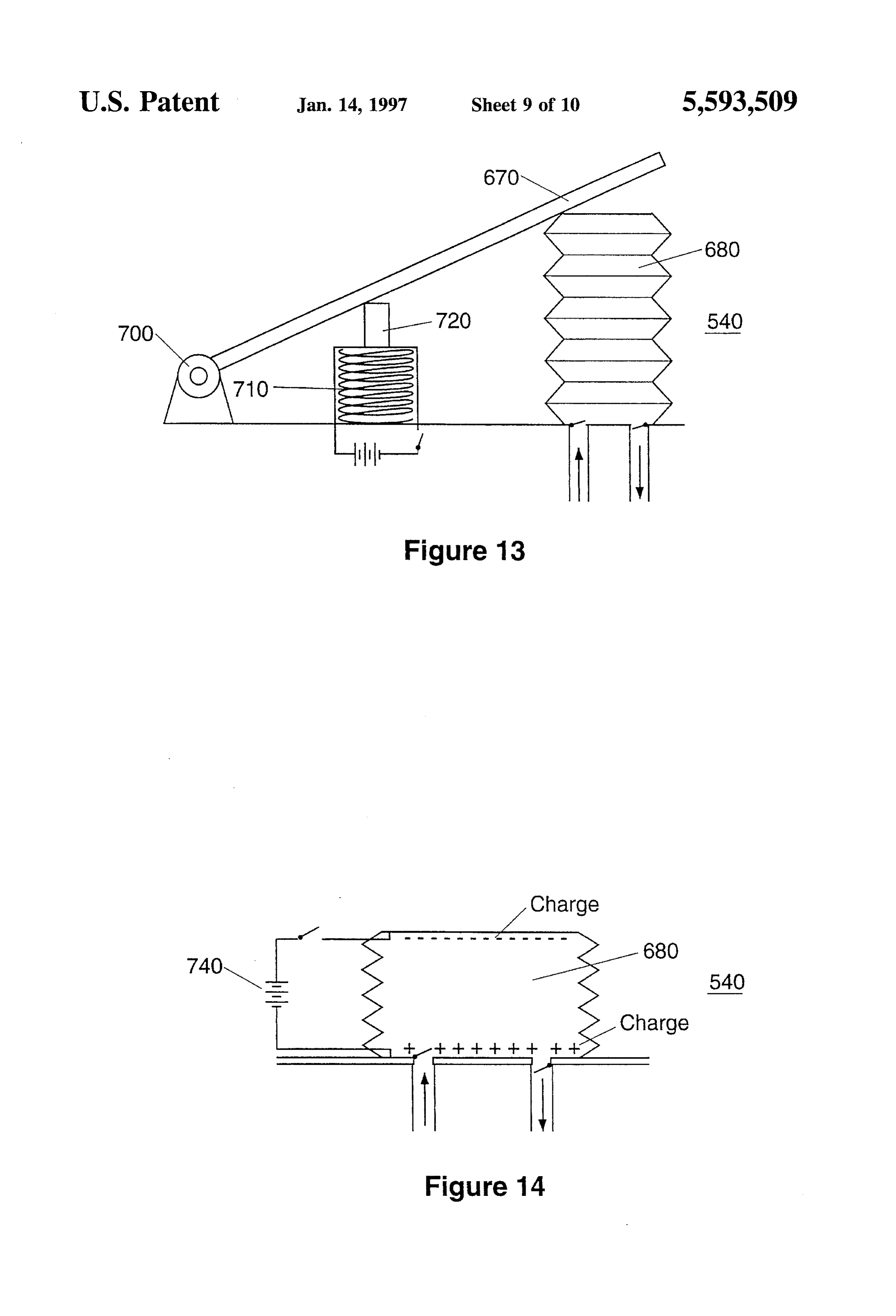
FIG. 12 is an alternative embodiment of the air pump of FIG. 3 is a block diagram of the components in the TPV FIG. 11. 50 power chamber 200 in a preferred embodiment of the FIG. 13 is an alternative embodiment of the air pump of present invention. The power chamber 200 is the heart of the FIG. 11 that uses magnetic forces to drive the bellows. TPV power source and will be described first. FIG. 14 is an elevational perspective of an alternative A starter means 280 is given a command to ignite a fuel and oxidant.
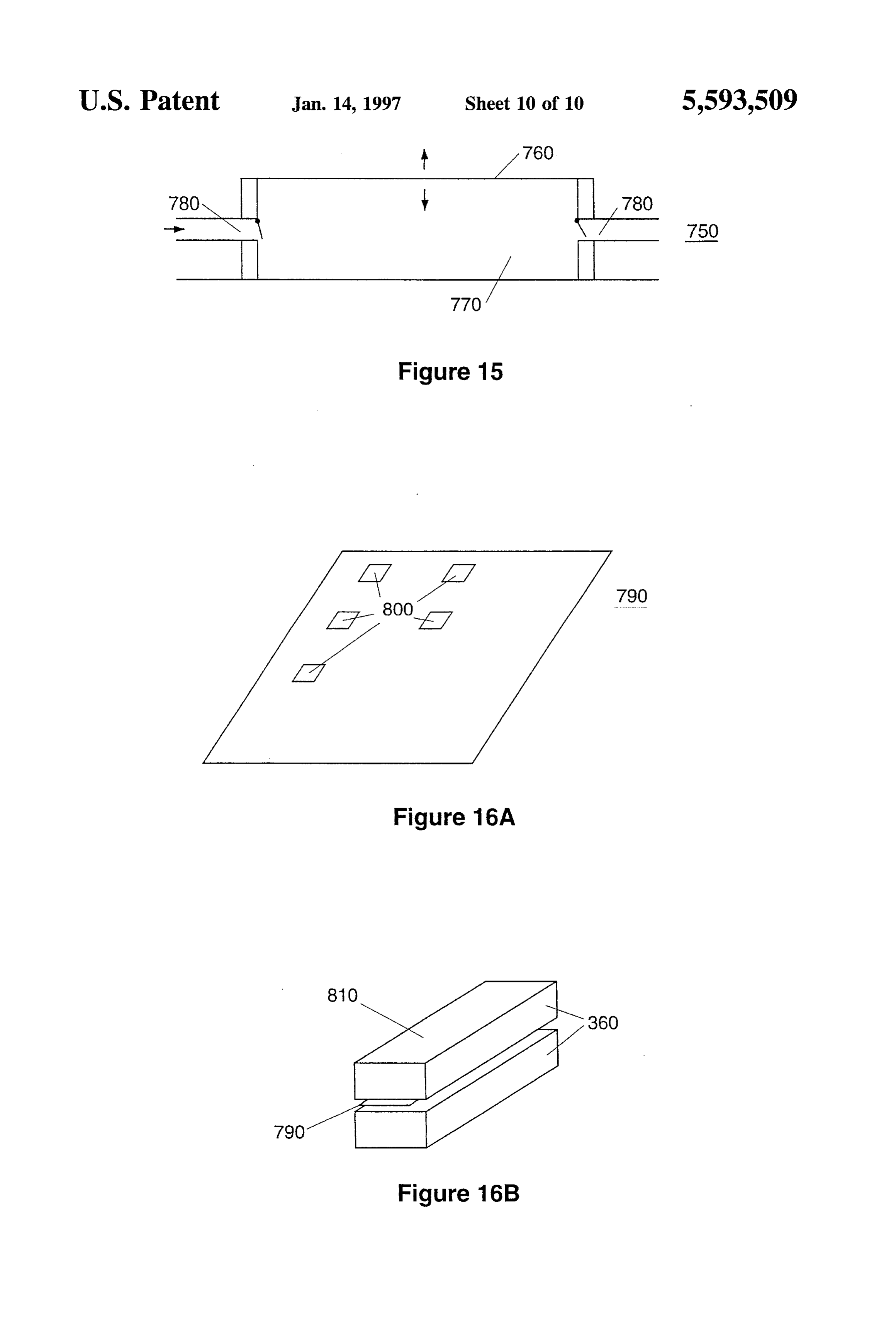
embodiment of the air pump of FIG. 11 that uses electro 55 static forces to drive the bellows. A heat source chemical reactor 210 (combustion chamber FIG. 15 is an elevational view of a fuel pump for moving above) forms the core of the power chamber 200. The fuel into the heat source chemical reactor of FIG. 5. chemical reaction is the combustion of any appropriate fuel with air as the oxidant. The fuels envisioned for use in the
FIG. 16A is a perspective view of a TPV ASIC device present invention have high energy densities such as butane, with a plurality of TPV burners. 60 propane, liquid petroleum gas (LPG), alcohols, oils and FIG. 16B is a perspective view of an ASIC disposed diesel fuels. A preferred fuel is butane. Butane has the between an upper and lower super insulator. advantage of providing a pressure sufficient to drive itself DETAILED DESCRIPTION OF THE into the burner when stored at room temperature. Butane and INVENTION air are burned in the reactor chamber 210 to generate heat 65 typically between 1000 and 1500 degrees Celsius. This
FIG. I shows a macro thermophotovoltaic power genera temperature is required to heat the burner 220 coated with an tor 10 as taught in the prior art. As shown, the cross-sectional emissive spectrum converter (ESC) 230. The ESC 230 must
Page 15
be heated to incandescence where the radiated light gives off FIG. 4 is a flowchart of the interactions described above photon energy within a narrow bandwidth or wavelength. between components of the TPV power chamber 200. Aheat An efficient TPV power chamber 200 will tailor the source reactor 210 receives as input a hot fuel 300 and hot wavelength and therefore the energy of emitted photons air 310 (oxidant), having been preheated by the heat recu from the ESC 230 to just above the band gap of the perator 270. The preheated fuel 300 and air 310 results in photovoltaic element 240. In doing so, the maximum less fuel being required to heat the chamber 210 to approxi amount of photon energy received by the photovoltaic 240 mately 1400 degrees Celsius. The fuel 300 and air 310 are element is converted into electricity. Photon energy directed ignited by a starter means 280 which provides an igniting at the photovoltaic cells 240 too far below and above the spark or other combustion igniting means such as a glowing band gap is wasted by heating the photovoltaic element 240, 10 hot wire. Hot exhaust 330 is vented from the heat source and this thermal energy is not easily recovered. Furthermore, reactor 210 and sent to the heat recuperator 270 (not shown). this excess heat can damage or shorten the life of the Heat from the reactor 210 warms a burner to incandescence, photovoltaic cells 240.
the burner being in direct contact with the ESC 230. At
Surrounding the heat source reactor chamber 210 is a incandescence, the ESC 230 will radiate the majority of its super insulator 360. Such an insulator 360 is required by a 15 photon energy at a particular band gap energy. The photon miniature TPV power source for two reasons. In practical energy is just sufficient to create electron-hole pairs in the terms, the small physical dimensions of the burner 220 photovoltaic element 240. Electricity is the output of the PV coated with the ESC 230 results in the burner 220 cooling element 240.
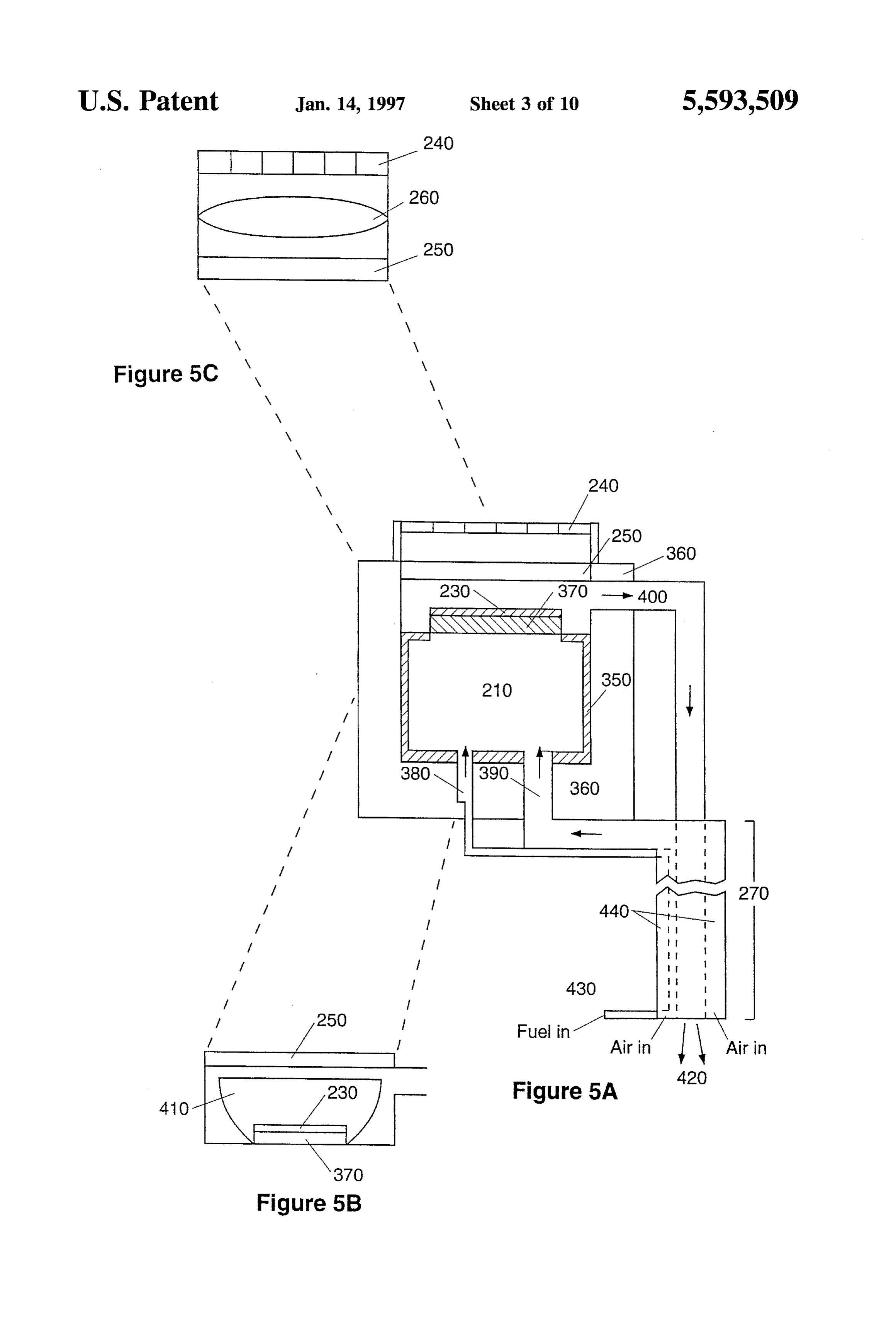
rapidly. The super insulator 360 is used to retain heat within FIG. 5A is an elevational cut-away view of a TPV power the heat source reactor chamber 210. The second reason is 20 that the TPV power source is intended for portable or chamber made in accordance with the preferred embodiment hand-held devices that must necessarily be cool to the touch. of the present invention. The heat source reactor chamber 210 has walls 350 comprised of a thermally resistant metal,
To help concentrate the photon energy of the ESC, a metal alloy, or ceramic sufficient to contain the combustion reflector dish 410 is a possible addition to the system, but a process within. Immediately adjacent to the chamber walls possible tradeoff is the introduction of wider gaps between 25 350 is a surrounding super insulator 360. The insulator 360 components. The dish 410 focuses photon energy that would is comprised of the same materials used for the heat shield otherwise not strike the photovoltaic element 240. ceramic tiles on the space shuttles. These are sometimes The photovoltaic element 240 of the present invention is called fibrous refractory composite insulation (FRSI) and protected by a transparent planar film 250. The film is High temperature Reusable Surface Insulation tiles (HRSI). transparent to allow photon energy from the ESC 230 to 30 The interesting property of this insulator 360 is that not only reach the photovoltaic element 240. The film 250 also is the heat contained within the chamber 210 enabling the protects the photovoltaic element 240 by reflecting excess majority of the heat to be transferred to the ESC 230 coating heat energy above and far below the required band gap the burner 370, but the outside surfaces of the insulator 360 energy that would normally heat and possibly damage the will be cool to the touch despite the approximately 1400 photovoltaic cells 240. In addition, by reflecting the heat 35 degrees Celsius temperature within. The super insulator 360 back to the ESC 230, the burner 220 and heat source reactor will be of a thickness measured in millimeters. 210 can operate more efficiently. The reactor chamber 210 has two inputs. The first input is It is possible that a very large amount of excess heat a fuel inlet 380. In a preferred embodiment, butane is the energy will be radiated by the ESC 230. If such is the case, fuel. To generate 30 watts of thermal power within the a thin diamond coating, or thermally conducting equivalent, 40 chamber 210, 0.000625 grams per second of butane must be could be applied to the film 250 to provide additional heat burned. A small fuel pump outside of the power chamber sinking capabilities, and transfer heat back to a heat recu will be described later that accomplishes this task. perator 270 for use in the system. The reactor chamber's 210 second input is an oxidant To help concentrate the photon energy of the ESC 230, a 45 inlet 390. Using oxygen within air as the oxidant, air will be micro-lensing system 260 is also envisioned in which a lens pumped into the chamber 210 and the fuel/air mixture will 260 focuses the radiated photon energy from the ESC230 on be burned to create the approximately 1400 degrees Celsius to the photovoltaic element 240, thereby reducing energy temperature required for ESC 230 incandescence. lost to heat and light refraction. The microlensing system Burning 0.000625 grams per second of butane requires 260 is also protected from the excess heat of the ESC230 by 50 approximately 10 cc of airper second to be pumped through the transparent thin film 250. the chamber 210. The air inlet 390 will necessarily be small, The photovoltaic element 240 in a preferred embodiment approximately 1 to 2 mm in diameter. Pushing this signifi comprises an array of high efficiency photovoltaic cells cant amount of air through such a narrow passage 390 made of silicon or some other semiconductor for conversion requires the use of an air pump outside the power chamber of the light from the ESC 230 directly to electricity. Photon 55 200 which will also be described later. energy of a particular wavelength that is absorbed in a At the top of the reactor chamber 210 is the burner 370, semiconductor pn junction will give rise to an electric and its dimensions are chosen based on the efficiency of the potential. overall system and the desired power output. In a preferred Finally, the heat recuperator 270 makes use of the heat embodiment of the present invention, the desired power energy of exhaust gases resulting from the combustion of 60 output is 3 watts, although dimensions and specifications of fuel and an oxidant. This heat is channeled to the incoming the TPV power source can be varied to obtain more or less fuel and oxidant inlet passages. By preheating fuel and an power. TPV devices today achieve three percent efficiency. oxidant, the temperature of the heat source reaction chamber Under these conditions, the reactor chamber 210 would have 210 will not be significantly reduced when the fuel and air to produce 100 watts of thermal power. A "Goldstein' burner are pumped into it. This results in less fuel being expended 65 is claimed to produce 945 watts of power per square to maintain the chamber 210 at an average temperature centimeter of burner. Nevertheless, using present day TPV sufficient to cause ESC 230 incandescence. devices, a square burner surface would be 3 mm on each
Page 16
edge at three percent efficiency. It is envisioned that the TPV to the PV element 240, similar to the reflective dish 410. As system in the present invention will have efficiency of ten with the insertion of the reflector dish 410, adjustments to percent when using aheat recuperator. Therefore, the reactor the gap spacing, this time between the planar protective chamber need only provide 30 watts of thermal power, sheet 250 and the PV 250, might be necessary to place the resulting in a reduction of the square edge lengths of the microlens 260 in the system.
square shaped burner to 1.7 mm. The array of photovoltaic (PV) cells 240 receiving the Coating the burner 370 surface is the emissive spectrum photon energy of the incandescent ESC 230 produces elec converter (ESC) 230. Typically, a rare earth oxide 230 is tricity. These devices are well known to those skilled in the coated directly onto the heat source, in this case the burner art. Typically, silicon semiconductors are used because they 370, to a depth less than 1 millimeter thick. By choosing the 10 are easy and inexpensive to manufacture. However, germa type of oxide carefully, the converter can be tailored to nium might be substituted for silicon because of the similar produce a very specific emission spectrum to match that of band gaps (1.1 ev for silicon and 0.7 eV for germanium), and most known photovoltaic devices. This coating is well the ability to tailor wavelengths produced by the ESC by described in prior art. using different rare earth oxides and combinations thereof. Spaced a distance of approximately 1 mm from the top of 5 Finally, the heat recuperator 270 of the preferred embodi the burner/ESC surface 370/230 in a preferred embodiment ment is designed to utilize wasted heat energy. This element is a thin transparent planar protector sheet 250. The sheet "recuperates' heat from the exhaust gas stream 400 by 250 serves two purposes. First, the sheet 250 separates the transferring heat to the fuel and air being pumped into the region around the ESC 230 from the photovoltaic (PV) reactor chamber 210. The fuel and air are relatively "cold' element 240. Hot exhaust gases 400 around the ESC 230 20 introduced directly into the reactor chamber 210 from a
must be vented from the area to allow more air into the fuel reservoir and air intake. The result would be a cooling reaction chamber 210 for combustion, and the exhaust gases of the chamber 210. More fuel would then be required to 400 will be used by the heat recuperator. Second, the sheet maintain reactor chamber 210 temperature at ESC 230 250 reflects the spectral components not used by the PV incandescence, reducing efficiency of the system and element 240 back to the ESC 230, further helping to keep the 25 increasing fuel consumption, thereby decreasing the time ESC 230 incandescent and the whole device operating more between cooling fuel reloading. The recuperator 270 minimizes the effect of fuel and air by passing heat from exhaust efficiently. The gap between the planar sheet 250 and the
ESC 230 of 1 mm may be adjusted depending upon the basis gases 400 to the fuel and air in the chamber 210 inlets 380 of heat loss resulting from pumping air through the system, and 390, resulting in a higher average ESC 230 temperature. and recuperation needs. 30 The added benefit of a heat recuperator 270 is the cooling of Spaced a distance of approximately 1 mm on the opposite the expelled exhaust gases 400. Being used in portable or side of the planar protector sheet is the PV element 240. This held close devices
where the TPV power source might be person's face or hands, it is important that gap is chosen as a function of the size of the PV 240, and 1 gases 400 are not expelled at the high temperatures found in mm is appropriate for a PV sheet 240 of a few square the reactor chamber 210.
centimeters in area. 35
It should be noted that gaps up to 1 cm on either side of theThe design of the heat recuperator 270 is determined by geometry of heat reactor inlets 380 and 390, and exhaust the planar protector sheet 250 may be appropriate, depend gases 400 output. Exhaust gases 400 leave the reactor ing upon the heat recuperation needs, area of PV sheet 240 chamber 210 through a single exhaust port 420. However, and air flow considerations. The principal constraint on gap 40 there are two input passages 430 and 440 that require width is interference with the optical transfer of energy from heating. A preferred embodiment for the recuperator 270 is the ESC 230 to the PV element 240. The gap represents a the counter-flow "chimney” design. The exhaust gases 400 geometric loss of light that would otherwise have gone to the are driven from the reactor chamber 210 through as long a PV element 240. Minimizing the gap will minimize photon shaft as possible. The longer the shaft, the more opportunity energy loss, and increase efficiency of the overall system. 45 there is for heat to transfer. The shaft will be comprised of Although in the preferred embodiment described above a highly thermally conductive material. At present, both the gaps between the ESC 230, the planar protector sheet metals and ceramics are envisioned as suitable heat 250 and the PV element 240 could be as small as 1 mm, there exchanging materials. The more heat transferred from the are alternative configurations and additional components exhaust gases to the fuel and oxidant, the more efficient the that can provide enhancements to the power chamber 50 TPV power source will be.
design. For example, in the gap between the planar protector Regarding specific geometry of the counter-flow chim sheet 250 and the ESC 230, the gap could be widened to neys, a preferred embodiment would be a "flat-plate' chim permit the insertion of a reflector dish 410 shown in FIG.5B. ney design illustrated in FIG. 6A, where all the chimney The dish 410 would concentrate photon energy from the surfaces are flat planes. The flat-plate design simplifies ESC 230 and reflect it through the planar protector sheet 55 several construction features of the chimney. For example, 250, thereby reducing loss of misdirected photon energy. although the outer shaft 450 for incoming air flow com This dish would be centered around the burner and ESC pletely surrounds the inner exhaust gases shaft 460 thus coating 370/230 with an aperture where the bottom of the providing the maximum amount of surface area for heat dish would normally be found, the aperture fitting around the exchange between air and exhaust gases, there is the matter burner 370. The interior surface of the dish 410 would be 60 of where to place the much narrower fuel line 470 that also coated with a reflective material, such as aluminum to needs preheating. The fuel line 470 is necessarily narrower enhance its effectiveness. because the volume of fuel pumped to the reactor chamber A further enhancement of the TPV power chamber is the 210 is significantly smaller than the volume of air. The inner addition of a microlens 260 as seen in FIG. 5C. Most likely, shaft 460 in this preferred embodiment comprises a four a lens 260 would be placed in the gap between the planar 65 sided shaft 460, but it should be realized that a number of protective sheet 250 and the PV element 240. The lens 260 sides could be used. The fuel line 470 is easily placed flush would permit additional focusing and channeling of light on against a single outer side 490 of the inner shaft 460, being
Page 17
spread broadly against the shaft wall, and extending only a refueling of the fuel tank 520 and when power demand short distance into the inlet air flow path. Such a piggy-back increases sharply and additional TPV chambers 200 are configuration will only marginally reduce heating of the heating up.
inlet air flow, allowing the substantial majority of exhaust FIG. 10 is a flowchart showing the interaction of all heat to heat the inlet air. A slight modification to the design components of the TPV power system 600. The fuel tank would be the addition of a diamond film coating around the 520 provides the fuel to a fuel pump 530, which pumps cold outer wall 490 of the inner shaft 460. The coating would be fuel to the heat management system (heat recuperator 270). extended to surround the fuel line 470 to provide even greater heat transfer. A further modification would be the Likewise, the air pump 540 draws in air and pumps the cool replacement of the inner wall 490 separating the inner shaft 10 air into the heat management system 270. The heat man 460 exhaust gases 400 and the fuel line 470. The highly agement system is comprised of the heat recuperator 270, conductive nature of the diamond film would allow even using excess heat from exhaust gases 400 to preheat the fuel greater heat transfer. It should be noted that because the and air, moving cooled exhaust 400 out of the system 600. design does not need to operate under a severe pressure The preheated fuel and air are forced into the heat source differential, structural constraints are minimal. reactor chamber 210 of the power chamber 200, which An alternative embodiment of the flat-plate counter-flow 15 expels hot exhaust 400 back to the heat recuperator 270. The chimney design is illustrated in FIG. 7, and would be the power chamber 200 produces electricity which is routed addition of vanes 500 extending from the surface of the outer through the power conditioner 550, and then to the power walls of the inner shaft 460 into the inlet air flow path. This storage device 560. The portable or hand-held device being modification increases the exchange of heat from the powered by the TPV power source 600 would draw power exhaust gases 400 to the air by forcing the air flow past a 20 from power storage 560 on demand.
larger heated surface area. The vanes 500 are to be made of FIG. 11 is an illustration of an air pump 540 as envisioned highly thermally conductive material. It is envisioned that in a preferred embodiment of the present invention. A the vanes will be comprised of diamond films or thermally substantial amount of air must be moved through the system similar material.
600 to provide the oxygen needed for combustion in the
Another alternative embodiment of the heat recuperator 25 reactor chamber 210. While a fan might work, it is envi 270 would be the construction of a columnar counter-flow sioned in a preferred embodiment that miniature bellows chimney design as shown in FIG. 8. This particular con 540 will be used. Bellows are quiet and efficient devices for figuration is more of a design choice prompted by physical moving air. The air in the TPV system actually serves a dual constraints of the device in which the TPV power source purpose. First, the air supplies the oxidant for reactor would be operating. A cylindrical design may prove advan 30 chamber 210 combustion. Second, the air acts as a coolant. tageous, and does not unduly complicate the device. Instead The cooling property is essential if the TPV power source is of vanes extending out from flat sides of an inner shaft, to work in portable and hand-held devices. annular rings 510 around the inner column 460 would The approximately 10 cc of air flow per second required increase the surface area in contact with the inlet air flow.
The fuel line 470 would only cause a slight bump on the 35 for combustion will be insufficient to cool the exhaust gases otherwise circular exhaust gases column 460. 400. Therefore, a series of bellows 540 will be used to supply a total of around 40 cc of air to reduce exhaust gas
FIG. 9 is a block diagram of the additional TPV system 400 temperatures to a tolerable level. 600 components in a complete power generation system.
The power chamber 200 has been described in FIGS. 3–8. 40 structural A single bellows air pump 540 in FIG. 11 illustrates the The additional components shown in the block diagram are features of the design. In a preferred embodiment, necessary for the construction of a miniature TPV power the air pump 540 takes advantage of waste heat and a series of microvalves 640 and 660. A working fluid 620 that source 600, and introduce new issues of novelty of the condenses at room temperature but easily converts to gas is present invention. The fuel tank 520 may be filled with a variety of different fuels such as butane, propane, LPG, and 45 exhaust gasespartially sealed in a collapsed liquid bellows 630. Hot 400 are routed by a microvalve to heat the various other alcohols, as well as oils and diesel fuels.
Butane is the fuel of a preferred embodiment because of the fluid 620, which expands inside the bellows 630. The pressure it provides to assist the fuel pump 530. working fluid 620 will turn to gas 650 when heated by exhaust gases 400 which are only 100 degrees Celsius,
The fuel pump 530 and air pump 540 have been men which is significantly lower than the 1400 degree operating tioned before, and will be described in detail in FIGS. 11 to 50 temperature of the reactor chamber 210. When the sealed 15. The final two elements of a complete TPV power source liquidbellows 630 expands, it forces a bar or plate 670 at the 600 are a power conditioner 550 and power storage device top of the bellows 630 to also rise. This bar or plate 670 is
connected at both ends to the top surface of air bellows 680.
The power conditioner 550 serves the function of provid When the bar or plate 670 rises because of pressure from the ing clean energy free of power spikes and drops. It also 55 liquid bellows 630, the two air bellows 680 are also forced serves the purpose of adjusting power output of the TPV to rise and fill with air. When the sealed liquid bellows 630 system 600 by sensing load changes. For example, if the is fully inflated, the microvalve 640 cuts off the exhaust device being powered by the TPV energy source 600 such as gases 400, and a second microvalve 660 opens to enable the a notebook computer activates a hard drive, the load will flow of cool air, from the environment, to flow over the increase. To handle the load, additional TPV power cham 60 bellows 630 and condense the working fluid 620. The air bers 200 would be started until sufficient energy to handle bellows 680 then force air into an air inlet, some of which the load was produced. Likewise, when power demands will be siphoned off to cool another expanded sealed liquid drop when the hard drive spins down, it is better to deacti bellows.
vate power chambers 200 and save fuel rather than waste This air pump design is very energy efficient because it fuel if the power storage device 560 is already fully charged. 65 draws almost no power from the system 600, but instead The power storage device 560 enables the TPV power utilizes heat that is otherwise considered waste heat to create source 600 to supply energy, for example, during times of mechanical motion to drive air into the combustion chamber.
Page 18
Another feature of the design in FIG. 11 is that the use of two FIG. 16A is an illustration of a planar IC sheet 790 as the air bellows allows a balanced rise and fall of the bar or plate present invention appears in an Application Specific Inte 670. The height to which the bellows must rise to get a grated Circuit (ASIC) design. Multiple burners 800 coated certain volume of air flow is thus decreased because of the with ESCs are formed in the planar surface. The burner additional air flow from using two air bellows. dimensions are as described in FIG. 5A where the edge The bellows consist of very thin and flexible material. length is given as 1.7 mm, sufficient to produce the 30 watts They do not need high strength because the mass of air to be necessary for a 3 watt electric power output at 10 percent moved is about 0.01 grams per second and the pressure efficiency. With the burners on the silicon wafer is the difference for less than one atmosphere. A bellows bladder control circuitry whereby the burners are controlled. That is of nearly Zero mass can thus move the required air mass. A 10 to say that burners are turned on and off to follow the load suitable material in a preferred embodiment would be mylar. demands of whatever device is being powered. An alternative embodiment of the bellows of FIG. 11 is FIG. 16B shows a super insulator 360 above and below illustrated in FIG. 12. In this design, a single air bellows is the planar IC sheet 810. The super insulator 360 is capable used to move air to the power chamber 200 in a more of insulating 1000 degree Celsius temperatures from room familiar bellows configuration. The liquid bellows 630 15 temperature over dimensions measured in millimeters. The pushes up on a bar 670 connected to the top of an air bellows nearly 1400 degree Celsius temperatures of the burner will 680 at the moving end, and to a hinge 700 at a rotatable end. be easily handled within the confines of the ASIC sheet 810. Otherwise, all features and movements of exhaust, cooling It is the super insulator's 360 characteristic abilities that will air, and inlet air pumped to the power chamber is the same. allow the TPV power source 600 to compete with batteries FIG. 13 is an alternative embodiment of an air pump 540 20 of ItAAA size.
is to be understood that the described embodiments of using an air bellows 680 that does not use waste heat from exhaust 400. While less efficient, this air pump 540 might be the invention are illustrative only, and that modifications a small 'start-up' system that would eventually supplement thereof may occur to those skilled in the art. Accordingly, the main air pump. This alternative would operate effec this invention is not to be regarded as limited to the tively as a start-up pump because it operates off electrical 25 embodiments disclosed, but is to be limited only as defined power to generate magnetic fields. The electrical power by the appended claims herein.
would be taken from the power storage device 560. We claim:
The air pump 540 would take the shape of a conventional 1. A miniature thermophotovoltaic (TPV) power chamber bellows 680 with a bar 670 attached to a hinge 700 end as means for use in portable and hand-held electronic devices, shown. The actuator of air pump movement in this device is 30 said power chamber means comprising:
a solenoid coil 710 and solenoid rod 720. The power through an energy source reactor chamber having a fuel inlet, an the solenoid coil 710 could be reversed if a driving force was oxidant inlet, and an outlet for heat and exhaust gases; required to help the contraction of the bellows 680. If a a burner element coupled to the outlet of said energy driving force is not required, power to the coil 710 is simply Source reactor chamber such that said burner element is removed allowing the solenoid rod 720 to fall back into the 35 heated by a burning of a fuel and an oxidant in said coil 710 as the air bellows 680 pushes air into the power chamber to produce photon energy; chamber.
an emissive spectrum converter disposed on an outer face
FIG. 14 is another alternative embodiment of an air pump of the burner whereby heat from the burner causes a 540 using a bellows 680 that does not use waste heat. This thermal excitation of said converter such that photon design is again less efficient, but this bellows might also be 40 energy is produced in a narrow spectrum, a small 'start-up' bellows that would eventually be turned a transparent protector sheet separated from and locally off or allowed to supplement the main bellows. This alter parallel to the emissive spectrum converter on the outer native would operate effectively as a start-up bellows because it operates off electrical power to generate electro burner face, said sheet reflecting excess heat energy Static charges from energy stored in the power storage 45 back to said converter, device 560. a hot exhaust port and shaft disposed between the energy The bellows 680 would have the shape of flat upper and source and the transparent protector sheet, whereby lower surfaces. Shown here in an edge on view, the inner exhaust gases from the combustion of said fuel and said plane surfaces of the bellows would be coated with a oxidant are expelled from the power chamber; conductor and prevented from electrically touching each 50 an array of photovoltaic elements spaced a distance from other. By attaching a power source 740, the conductive and parallel to the transparent protector sheet and Surfaces are charged like capacitors, and caused to repel or optically coupled to the spectrum converter, whereby attract each other. An attraction force will drive air out of the said array generates electricity in response to photon bellows 680 if it is being used in a start-up mode and the energy from said converter; larger waste heat bellows are not yet in operation. 55 a miniaturized air transport means to move air from the FIG. 15 is an illustration of a fuel pump 750 in a preferred ambient surroundings into the power chamber both for embodiment of the present invention. The fuel pump 750 is the purpose of providing oxygen and for thermal man required to pump approximately 0.0006 grams per second of agement, and fuel into the heat reactor 210 of the power chamber 200. As a heat recuperator means coupled to the hot exhaust port envisioned, the pump 750 is a piezoelectrically actuated 60 and shaft for reclaiming heat energy from the exhaust diaphragm 760. A thin sheet of piezo material 760 can be gases being expelled from the reactor chamber, flexed to draw fuel into a reservoir 770 through a fuel inlet whereby said exhaust port and shaft is thermally 780. Reversing or removing the electric charge from the coupled to a fuel line and an oxidant line to (i) preheat material 760 allows the piezo material to flex in the opposite said fuel and oxidant in the lines to increase efficiency direction, forcing fuel from the reservoir 770. A suitable 65. of the power chamber, and (ii) cool the exhaust gases material for the preferred embodiment is a thin sheet of PZT so that said TPV power chamber may be used in a (lead Zirconate titanate). hand-held device.
Page 19
2. The TPV power chamber means as defined in claim 1, having a cross section wherein there are two short sides wherein said chamber further comprises a reflector means protruding perpendicular from the inner shaft and a for focusing photon energy produced by the emissive spec longer outer side parallel to the curvature of the inner trum converter on to the array of photovoltaic elements. shaft, and wherein the fuel in the fuel line is preheated 3. The TPV power chamber means as defined in claim 2, by contact with the inner shaft, and wherein the fuel wherein the reflector means is an optically optimized shaped line is coupled at a first end to a fuel source and at a dish, with a portion of the bottom of the dish being removed second end to the fuel inlet of the reactor chamber. so as to create an aperture which is placed over the burner, 9. The heat recuperator means as defined in claim 7 or 8, the dish preventing an escape of photons not otherwise wherein a common wall of the inner shaft that separates the leaving the ESC in the direction of the array of photovoltaic 10 hot exhaust gases from the fuel is comprised of a thin elements by forming another optically optimized shaped cup shape projecting from the burner. diamond film for increased transfer of thermal energy 4. The TPV power chamber means as defined in claim 3, between the exhaust gases and the fuel. wherein the optically optimized shaped dish is a circular 10. The heat recuperator means as defined in claim 7 or 8, dish comprised of a ceramic or metal with an aluminized wherein the inner shaft includes a branch port and shaft reflective surface coating an inside surface of the dish. 5 coupled to the reaction chamber from a distal end whereby 5. The TPV power chamber means as defined in claim 1, some of the hot exhaust gases are fed back into said wherein the chamber further comprises a microlens for chamber.
focusing photon energy produced by the emissive spectrum 11. The heat recuperator means as defined in claim 7 or 8, converter onto the array of photovoltaic elements. wherein the inner shaft has a plurality of vanes extending 6. The TPV power chamber means as defined in claim 1, 20 from said shaft into the space between the inner and outer wherein the heat source reactor chamber is constructed of shafts at selected distances along the length of the inner shaft materials selected from the group consisting of heat resistant and at selected distances around the outer circumference of metals, metal alloys, and ceramics. the inner shaft to thereby increase the exchange of heat 7. The TPV power chamber means as defined in claim 1, energy between hot exhaust gases and the oxidant. wherein the heat recuperator means further comprises a 25 12. The heat recuperator as defined in claim 11, wherein flat-plate counterflow chimney, said chimney comprising: the vanes are comprised of thermally conductive diamond the hot exhaust gases shaft as an inner shaft with a films.
plurality of flat sides forming a conduit through which 13. The TPV power chamber means as defined in claim 1, the hot exhaust gases are removed from the power wherein the oxidant comprises air.
chamber, coupled at a first end to the hot exhaust port 30 14. The TPV power chamber means as defined in claim 1, and on a second end to a cold exhaust port, said cold wherein the burner coated with an emissive spectrum con port being directed away from the hand-held device; verter, the transparent protector sheet, and the array of the oxidant line as an oxidant intake shaft having a photovoltaic elements are comprised of thin films. plurality of flat sides, wherein said intake shaft sur 15. The TPV power chamber means as defined in claim 1, rounds the inner shaft and forms a conduit through 35 wherein the spacing between the burner and the transparent which incoming oxidant is preheated by contact with protector sheet is as small as 1 mm.
the inner shaft, fed to the reactor chamber, and coupled 16. The TPV power chamber means as defined in claim 1, at a first end to the oxidant inlet and at a second end to wherein the spacing between the transparent protector sheet an oxidant intake port, and and the array of photovoltaic elements is as small as 1 mm. the fuel line comprising a thin hollow shaft protruding 40 17. The TPV power chamber means as defined in claim 1, from a flat side of the inner shaft and having a rectan wherein the reactor chamber produces at least 30 watts of gular cross section, a smaller side of the rectangle thermal energy.
projecting away from the inner shaft and a longer side 18. The TPV power chamber means as defined in claim 1, of the rectangle being parallel to the flat side, wherein 45 wherein the burner element is as small as 1.7 mm on an edge, the fuel in the fuel line is preheated by contact with the and the burner face is approximately square. inner shaft, and wherein the fuel line is coupled at a first 19. The TPV power chamber means as defined in claim 1, end to a fuel source and at a second end to the fuel inlet wherein the fuel is selected from the group consisting of of the reactor chamber. butane, propane, LPG, alcohols, oils, and diesel fuel. 8. The TPV power chamber means as defined in claim 1, 50 20. The TPV power chamber means as defined in claim 1, wherein the heat recuperator means further comprises a wherein the energy source reactor chamber is insulated by a columnar counterflow chimney, said chimney comprising: super insulator which can insulate a 1000 degree Celsius the hot exhaust gases shaft as a columnar inner shaft temperature against room temperature over a few millime forming a conduit through which the hot exhaust gases terS.21. The TPV power chamber means as defined in claim 1, are removed from the power chamber, coupled at a first 55 including means for pumping a volume of air pumped to the end to the hot exhaust port and on a second end to a energy source reactor chamber at at least 9.5 cubic centi cold exhaust port, said cold port being directed away meters per second.
from the hand-held device;
the oxidant line as a columnar oxidant intake shaft, 22. The TPV power chamber means as defined in claim 1, including means for supplying at least 0.0006 grams per wherein said shaft surrounds the inner shaft and forms 60 second of fuel to the energy source reactor chamber when a conduit through which incoming oxidant is preheated the fuel is butane.
by contact with the columnar inner shaft, fed to the 23. The TPV power chamber means as defined in claim 1, reactor chamber, and coupled at a first end to the wherein the energy source reactor chamber is adapted to oxidant inlet and at a second end to an oxidant intake reach a temperature of at least 1400 degrees Celsius to cause port; and 65 incandescence of the emissive spectrum converter. the fuel line comprising a thin hollow shaft covering a 24. The TPV power chamber means as defined in claim 1, portion of the outer circumference of the inner shaft, wherein the energy source reactor chamber is a cylinder, the
Page 20
burner surrounds the reactor chamber, the emissive spectrum the power chamber, only allowing oxidant to leave the converter is disposed on the surface of the burner, the chamber when the bellows compresses; and transparent protector sheet surrounds and is spaced a dis a compression handle coupled at one end to the top tance from the emissive spectrum converter, and the array of surface of the oxidant chamber, and coupled at a photovoltaic elements surrounds but is not in contact with rotatable end to a hinge attached to the base and the transparent protector sheet. enabling the handle to rotate about said rotatable end, 25. The TPV power chamber means as defined in claim 1, having an actuator means a distal distance from the wherein the array of photovoltaic elements produces at least rotatable end, said actuator means pushing the handle 3 watts of electricity. away from the base to force oxidant to be drawn into 26. The TPV power chamber means as defined in claim 1, O the chamber, and pulling the handle toward the base to wherein the power chamber further comprises a control force oxidant out of the chamber. means for controlling (i) the flow rate of fuel and oxidant 33. The TPV power system as defined in claim 32, into the energy source reactor chamber, and (ii) the ignition wherein the actuator means comprises: of fuel and oxidant when starting.
27. The TPV power chamber as defined in claim 1, 15 a circular having a solenoid coil around a hollow center space, top and bottom face, attached at the bottom wherein the power chamber operates at at least ten percent face to the base and coupled to an energizing means efficiency. that when energized causes a current to flow in said 28. A miniaturized thermophotovoltaic electrical power coil, and system for use in hand-held devices, said system compris ing: a solenoid rod attached at one end to the compression a power chamber means for generating electricity wherein 20 handle and positioned to move in sliding engagement thermal energy enables a photon source to provide through the center space of the solenoid coil, said rod usable photon energy to a photovoltaic element to being magnetically attracted or repelled by the coil generate electricity, said power chamber means having depending upon the direction if current flow in said fuel and oxidant inlets and an exhaust gases outlet; coil, causing the compression bar to rise and draw oxidant into the oxidant chamber from outside the a fuel reservoir for storing a fuel to be used by said power 25 hand-held device, or to fall and force oxidant from the chamber means; chamber and into the power chamber means, depending a fuel pumping means for pumping the fuel stored in the upon magnetic attraction between the coil and rod. fuel reservoir to the fuel inlet of the power chamber 34. The TPV power system as defined in claim 31, means, wherein the bellows for drawing in oxidant from outside the an oxidant pumping means for pumping an oxidant to the 30 hand-held device and pushing it to the TPV power chamber oxidant inlet of the power chamber means; comprises:
a power conditioning means for enabling the system to an actuator means attached at a bottom face to a base, and respond to changing load conditions; at a top face to a midpoint of a handle; a power storage means for providing power for system 35 a first oxidant bellows attached at a bottom face to the start-up, and for providing backup energy reserves base, and at a top face to a first end of the handle, while the fuel reservoir is refilled; and having an inlet and an outlet port through the bottom a miniaturized air transport means to move air from the face and base, enabling oxidant to flow into the first ambient surroundings into the power chamber both for bellows through the inlet port when the handle rises, the purpose of providing oxygen and for thermal man 40 and enabling oxidant to flow out through the outlet port agement.
when said handle falls; and 29. The TPV power system as defined in claim 28, a second oxidant bellows attached at a bottom face to the wherein the fuel pumping means comprises a thin piezo electric material stretched over a hollow chamber having a base, and at a top face to a second end of the handle, fuel inlet port coupled by a first fuel line to the fuel reservoir, 45 having an inlet and an outlet port through the bottom and a fuel outlet port coupled by a second fuel line to the face and base, enabling oxidant to flow into the first power chamber. bellows through the inlet port when the handle rises, 30. The TPV power system as defined in claim 29, and enabling oxidant to flow out through the outlet port wherein the thin piezoelectric material of the fuel pumping when said handle falls.
means comprises lead zirconate titanate. 35. The TPV power system as defined in claim 34, 31. The TPV power system as defined in claim 28, 50 wherein the actuator means comprises a bellows filled with wherein the oxidant pumping means comprises a bellows. a working fluid, said working fluid which when heated 32. The TPV power system as defined in claim 31, quickly turns to gas and expands the bellows forcing the wherein the bellows for drawing in oxidant from outside the handle to rise, and which when cooled quickly turns to liquid hand-held device and pushing it to the TPV power chamber 55 and allows the bellows to compress and enabling the handle to fall.
comprises:
an oxidant chamber in the shape of a bellows, resting on 36. The TPV power system as defined in claim 31, a base, having top and bottom surfaces and side walls wherein the bellows for drawing in oxidant from outside the that stretch and compress the chamber perpendicular to hand-held device and pushing it to the TPV power chamber the top and bottom surfaces; comprises an oxidant bellows attached at a bottom face to a 60 base, having an inlet and an outlet port through the bottom an oxidant inlet port through the base and the bottom face and base, enabling oxidant to flow into the bellows surface of the oxidant chamber coupled by a first intake through the inlet port when the bellows rises, and enabling line to an intake port outside the system, only allowing oxidant to flow out through the outlet port when the bellows the entry of oxidant into the chamber when the bellows fails, wherein an inside surface of the bottom face and an stretches; 65 inside surface of a top face are coated with an electrical an oxidant outlet port through the base and the bottom of conductor such that when the inside surfaces are electrically the oxidant chamber coupled by a second intake line to charged, the bellows expands and compresses.
Page 21
37. The TPV power system as defined in claim 36, 45. A method for generating electricity from a miniatur wherein the inside surfaces of the bellows are coated with a ized thermophotovoltaic (TPV) power source for powering conductor. portable and hand-held devices, said method comprising the 38. The TPV power system as defined in claim 31, steps of:
wherein the oxidant pumping means comprise mini- or 5 (a) providing a TPV power chamber comprising a starter micro-bellows. means, a heat source reactor chamber, a burner, an 39. The TPV power system as defined in claims 31, 32, emissive spectrum converter, a reflector dish, a protec 34, 35 or 36, wherein the bellows is comprised of mylar. tive sheet, a microlens, a photovoltaic array, a heat 40. The TPV power system as defined in claim 28, recuperator, and a super insulator, wherein the system further comprises a plurality of TPV O (b) providing a fuel reservoir and fuel pump for drawing power chambers on a single application specific integrated fuel from said reservoir and pumping it to the power circuit which are coupled together for increased electrical chamber;
power output.
41. The TPV power system as defined in claim 40, (c) providing a system of mini- or micro-bellows for wherein the system further comprises a control means for 5 drawing oxidant from outside the system and pushing controlling (i) the flow rate of fuel and oxidant into the it into the power chamber; plurality of heat source reactor chambers, and (ii) the (d) providing a power storage means for storing electrical ignition of fuel and oxidant when starting. energy produced by the power chamber; and 42. The TPV power system as defined in claim 28, (e) providing a power conditioner for controlling the wherein the system has a virtually infinite shelf life. 20 production of electricity as load demands fluctuate. 43. A method for generating electricity from a miniatur 46. A method for providing a miniaturized power source ized thermophotovoltaic (TPV) power chamber for use in a that can provide more electrical power for a greater amount TPV power source for powering portable and hand-held of time than conventional batteries, and be used in portable devices, said method comprising the steps of: and hand-held devices, said method comprising the step of (a) providing a heating means to raise the temperature 25 providing a miniaturized thermophotovoltaic (TPV) power above the auto-ignition point of a fuel in the presence source with a high effective energy density, and surrounded of an oxidant; by a super insulator such that the power source is cool to the (b) providing a photon source reactor chamber to provide touch when in use or when in operation. photons; . 47. The method as defined in claim 46, wherein the step 30 of replacing conventional batteries by the TPV power source (c) placing a protective locally planar sheet between the insulated by a super insulator further comprises the step of photon source and a photovoltaic array placed parallel using air to cool exhaust gases of the TPV power source, as to the photon source for receiving photon energy; well as to provide an oxidant for a fuel used by said power (d) directing the photons towards the photovoltaic array; SOCC.
(e) providing electrical contacts and attaching them to the 35 48. The method as defined in claim 47, wherein the step photovoltaic array to provide electricity; of using air to cool exhaust gases further comprises the use (f) providing a heat recuperator for reclaiming heat from of mini- or micro-bellows and microvalves to pump air into exhaust gases produced by the reactor chamber, and and out of the TPV power source.
preheating a fuel and oxidant fed to said chamber to 49. The method as defined in claim 48, wherein the step increase power chamber efficiency; and 40 of replacing conventional batteries further comprises the (g) surrounding the power chamber with a super insulator step of providing at least 3 watts of electrical power from the to increase chamber efficiency and to enable the cham TPV power source.
ber to be placed in hand-held devices. 50. The method as defined in claim 48, wherein the step 44. The method as defined in claim 43, wherein the step 45 comprises theconventional of replacing further step batteries with a TPV power source of providing a TPV power source of directing photons is enhanced by: that is at least ten percent efficient in conversion of thermal (a) providing a reflector dish between the photon source heat energy to electricity.
and the protective sheet so as to help focus photon 51. The method as defined in claim 47, wherein the step energy from the photon source towards the photovol of using air to cool the exhaust gases comprises the further taic array; and 50 step of using diamond coated thin films to increase heat (b) providing a microlens between the protective sheet transfer between air and exhaust gases.
and the photovoltaic array to further focus photon energy onto the array.
Provenance
- Collection
- Cited prior art
- Original PDF
- patentimages.storage.googleapis.com →
- Filed
- 1995-03-17
- Pages
- 21
- Method
- pdftotext (the PDF's own text layer) + pdftoppm 300dpi page scans
- Source
- Google Patents bibliographic record
- Granted
- 1997-01-14
- Inventors
- Anthony C. Zuppero; Barton Krawetz; C. Rodger Barklund; Gary D. Seifert; Lockheed Idaho Technologies Co
- Transcribed from
- patentimages.storage.googleapis.com →