patent · US5398663
Combustion of liquid fuels
21 March 1995
Page 1 — bibliographic record
IIIHHHHHHHHHIII USOO5398663A
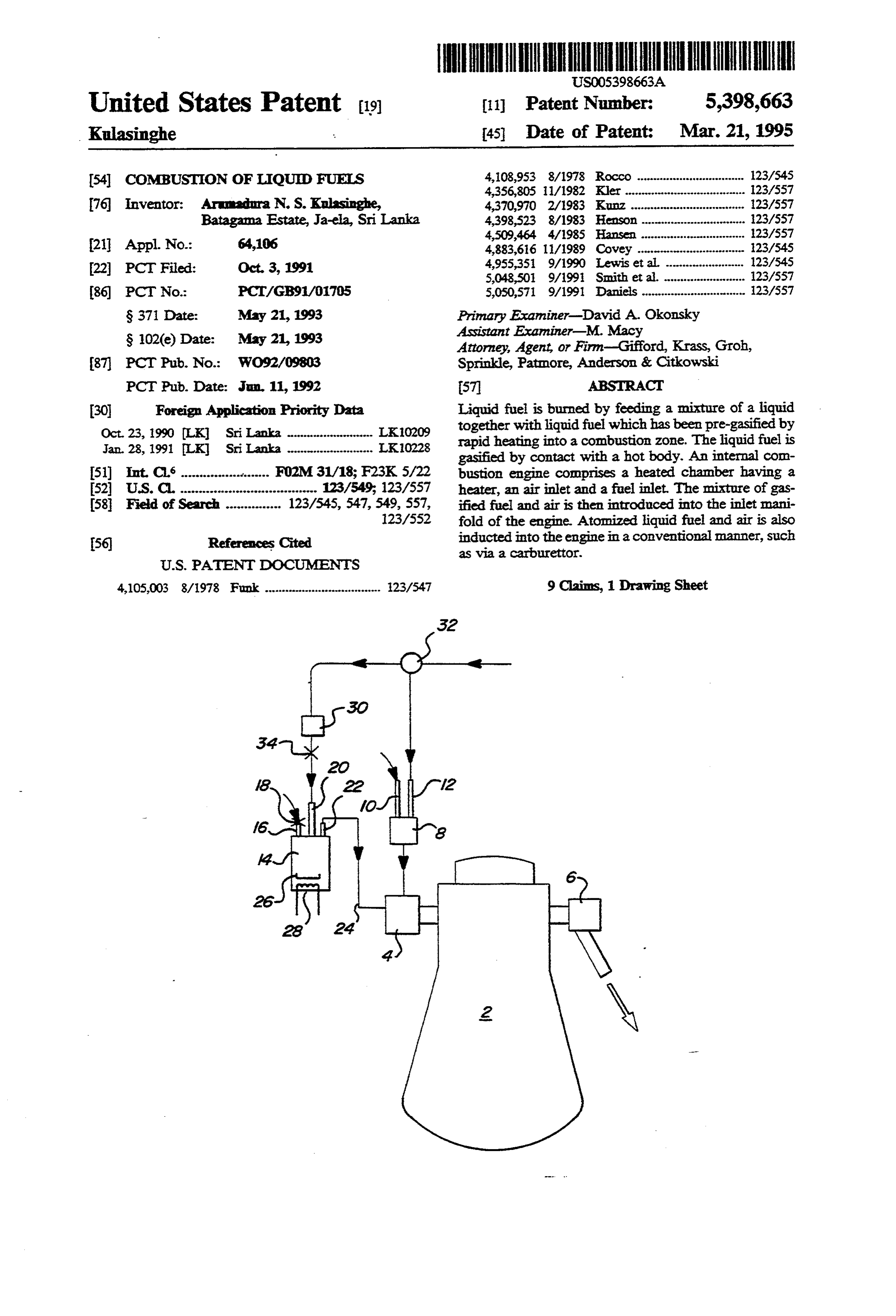
United States Patent (19) 11 Patent Number: 5,398,663 Kulasinghe . 45 Date of Patent: Mar. 21, 1995 (54) COMBUSTION OF LIQUID FUELS 4,108,953 8/1978 Rocco ... o 123/545
76 Inventor: Armadura N. S. Kulasinghe, 4,370,970 2/1983 Kunz ..... Batagama Estate, Ja-ela, Sri Lanka 4,398,523 8/1983 Henson ...
21 Appl. No.: 64,106 4,883,616 11/1989 Covey ........... oup- 23/545
22, PCT Filed: Oct. 3, 1991 4,955,351 9/1990 Lewis et al. ........................ 123/545
(86). PCT No.: PCT/GB91/01705 5,050,571 9/1991 Daniels ............................... 23/557 S371 Date: May 21, 1993 Primary Examiner-David A. Okonsky
S 102(e) Date: May 21, 1993 Assistant Examiner-M. Macy
Attorney, Agent, or Firm-Gifford, Krass, Groh, 87, PCT Pub. No.: WO92/09803 Sprinkle, Patmore, Anderson & Citkowski PCT Pub. Date: Jun 11, 1992 57 ABSTRACT 30 Foreign Application Priority Data Liquid fuel is burned by feeding a mixture of a liquid Oct. 23, 1990 LK Sri Lanka .................. L30209 together with liquid fuel which has been pre-gasified by Jan. 28, 1991 LK Sri Lanka ....... ... LK10228 rapid heating into a combustion zone. The liquid fuel is gasified by contact with a hot body. An internal com 51) int. Cl. .............aa.osses FO2M31/18; F23K 5/22 bustion engine comprises a heated chamber having a 52 U.S. Cl. ............................... 123/549; 123/557 heater, an air inlet and a fuel inlet. The mixture of gas 58 Field of Search ............... 123/545, 547,549, 557, ified fuel and air is then introduced into the inlet mani 123/552 fold of the engine. Atomized liquid fuel and air is also 56) References Cited inducted into the engine in a conventional manner, such as via a carburettor.
4,105,003 8/1978 Funk ................................... 23/547 9 Claims, 1 Drawing Sheet
Page 2
Drawing sheet — no readable text.
Page 3
COMBUSTION OF LIQUIDFUELS petrol, 180°-22 C. for kerosene, and 270°-330° C. for diesel oil.
FIELD OF THE INVENTION The invention further provides a method of improv The invention relates to the combustion of liquid 5 ing the fuel efficiency of an internal combustion engine fuels, particularly fuels such as petrol or gasolene, diesel which comprises inducting a part of the fuel in the oil and fuel oil, in internal combustion engines. gaseous form, the fuel having been gasified by feeding droplets of fuel into a cup heated to a temperature
BACKGROUND OF THE INVENTION above the boiling point of the liquid fuel such as to Liquid fuels have for many years been the source of O convert the fuel substantially instantaneously to the gas energy in internal combustion engines. The liquid fuelis phase; and the remainder of the fuel being in a non-gasi inducted into the cylinder in the form of a mixture of fied form, and burning the fuel in the combustion zone atomised fuel droplets and air. One of the problems of the engine.
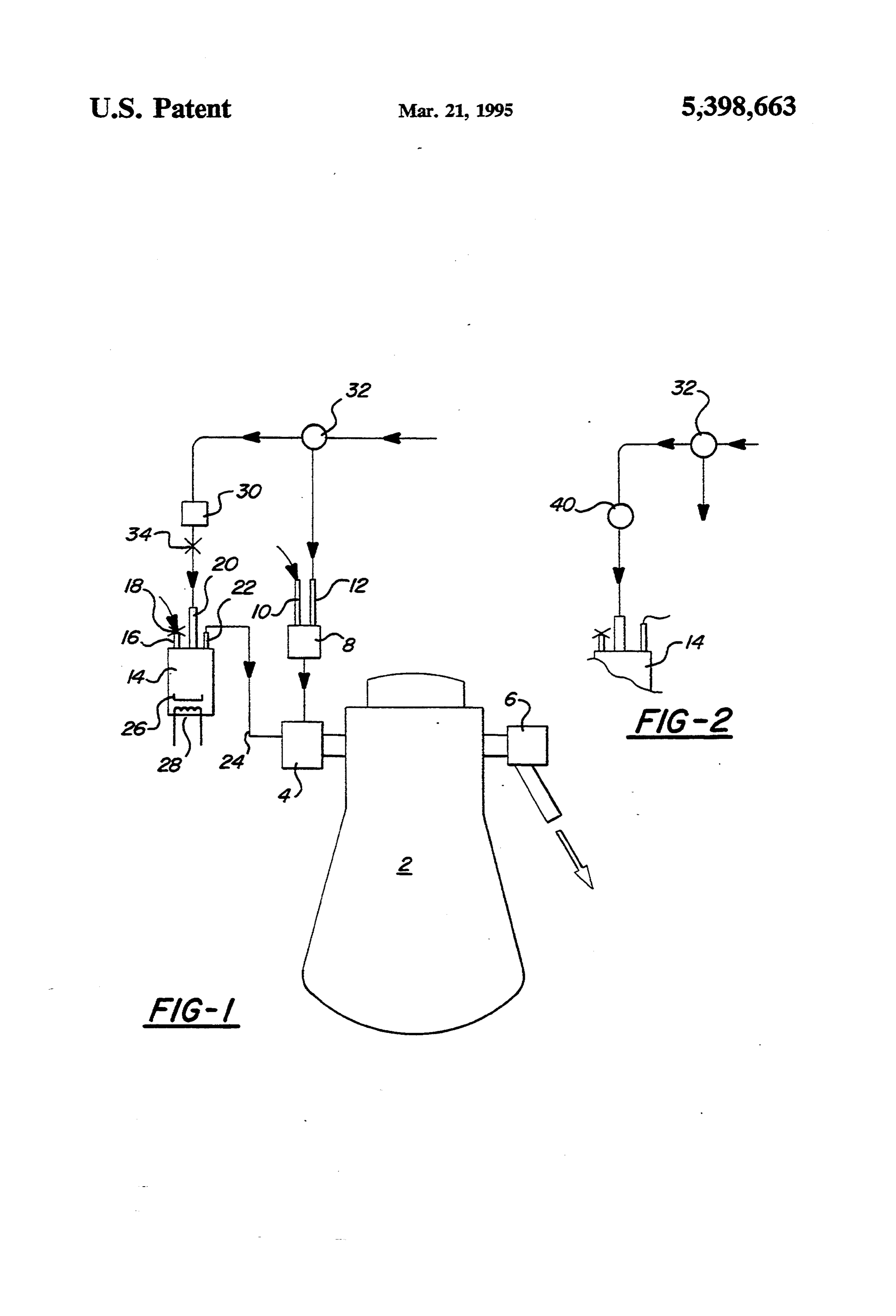
facing Automotive Engineers is that of ensuring even S BRIEF DESCRIPTION OF PREFERRED distribution of fuel within the air, and of ensuring com EMBODIMENT plete combustion of the fuel within the cylinder. Incon plete combustion leads to poor fuel economy and in Embodiments of the present invention will now be creased pollutant exhaust emissions. However, liquid described by way of example only with reference to fuel has the advantage of being easily storable and hav FIG. 1 which is a schematic diagram of an internal ing a high energy content per unit volume. It is also 20 combustion engine wherein part of the liquid fuel is known to run internal combustion engines on gaseous pre-gasified; and FIG. 2 which shows an alternative fuels such as methane, propane, butane and hydrogen. way offeeding liquid fuel to the gasifier. Combustion processes tend to be improved and pollut ant emissions are reduced. However, the handing and DETALED DESCRIPTION OF PREFERRED storage of compressed or liquified gases poses substan EMBOOMENT tial difficulties and is hazardous. In fact, special pressu The engine comprises an engine block 2 containing a rised storage vessels are required, which are generally plurality of cylinders and having an inlet manifold 4 and bulky. exhaust manifold 6. The engine operates according to a It is an object of the present invention to mitigate 4 stroke spark-ignition cycle and is provided with a these disadvantages. conventional carburettor 8 having an air inlet 10 and a SUMMARY OF THE INVENTON fuel feedline 12. The carburettorismounted on theinlet The present invention provides an internal combus manifold in the normal way.
The modification according to the present invention tion engine, which comprises an inlet manifold for in comprises ducting air into a cylinder constituting a combustion 35 trolled by aavalvechamber 14 having an air inlet 16 con zone for burning a liquid fuel; a heated chamber having top of the chamber.18There and a fuel inlet 20 provided at the is also an outlet 22 connected an outlet connected to said inlet manifold and having an by a pipe 24 for feeding gasified air inlet and a liquid fuel inlet for feeding part of the the inlet manifold 4. In the bottom fuel/air mixture into of the chamber there liquid fuel into the chamber, a heating means in the is provided a cup 26 heated by means of an electrical chamber to convert said part of the hiquid fuel to the gas 40 phase, the heating means comprising a heated cup heater 28 connected to the battery of the engine (not heated to a temperature above the boiling point of the shown). The apparatus is operated as follows. The engine is liquid fuel such that droplets of liquid fuel received in the heated cup are converted substantially instanta started using a starter motor (not shown) in the normal neously to the gas phase prior to being fed to the con way with part of the fuel requirement of the engine bustion zone. passing to the carburettor and the other part passing It is preferred that the gasified fuel be fed (in admix through inlet 20 into the heated chamber 14 and thence ture with air) into the inlet manifold of the engine. The into theinlet manifoldasagasified fuel/air mixture. The remainder of the liquid fuel is fed in atomised form in majority of the air requirements for the engine pass conventional manner either as a mixture of air and fuel through inlet 10 and carburettor 8, though aminor flow droplets via the carburettor into theinlet manifold or by of air passes through inlet 16 and heated chamber 14 to direct fuel injection into the cylinder. sweep the gasified fuel into the inlet manifold. The In a diesel engine, a minimum quantity of diesel fuel heated cup 26 is maintained at approximately 120° C. by in liquid form (usually less than 20%, preferably less the electrical heater 28 though the precise temperature than 15% of the total fuel) isfed through the injectorsin 55 will depend upon the amount of fuel passing through order to provide a correctly timed induction and igni the heated chamber. If necessary, the cup 26 may be tion of fuel. thermostatically controlled to maintain a particular The heated cup is provided with an air inlet to allow desired temperature which is sufficient to completely passage of air therethrough in order to flush the gaseous gasify the liquid fuel before it passes out of the chamber fuel into the inlet manifold. In order to control the flow 14. Droplets of liquid fuel fall from inlet 20 into the of air, a valve may be provided on the air inlet to a heated cup 26 where they become substantially instanta chamber containing the heated cup. neously converted to gas. The flow of air through air The heating means may be an electrical heater, or inlet 16 is controlled by valve 18 such as to efficiently heating may be achieved by means of hot exhaust gas transfer the gasified fuel into the inlet manifold with a from the engine passing through a heat exchanger, or by minimum delay in order to avoid any acceleration lag. means of a liquified petroleum gas (LPG) burner. Valve 18 is manually adjusted or linked to the accelera Clearly, more heat is required to gasify higher boiling tor pedal to ensure automatic operation. The flow of hydrocarbons. For example, the heating means is gener liquid fuel into the heated chamber via inlet 20 is con
Page 4
trolled by the reduced pressure in the inlet manifold 4. 1. An internal combustion engine, which comprises Once again, the air inlet valve 18 is Operated so as to an inlet manifold (4) for inducting air into a cylinder maintain the desired reduced pressure in the chamber 14 constituting a combustion zone (2) for burning a liquid and thus adjust the liquid fuel flow into the heated fuel; a heated chamber (14) having an outlet (22) con chamber. Generally, the inlet 20 will be connected to a 5 nected to said inlet manifold and having an air inlet (16) float chamber 30 in order to provide a flow of liquid and a liquid fuel inlet (20) for feeding part of the liquid fuel controlled by a valve 34 to the heated chamber 14. fuel into the chanber; a heating means (28 ) in the Alternatively, as shown in FIG.2, the liquid fuel can be chamber to convert said part of the liquid fuel to the gas introduced by means of positive displacement variable phase, the heating means comprising a heated cup (26) delivery pump 40. This feeds fuel directly into the O heated to a temperature above the boiling point of the chamber without the need for the float chamber or liquid fuel such that droplets of liquid fuel received in control valve. The ratio of atomised fuel passing into the heated cup are converted substantially instanta the inlet manifold from the carburettor 8 and the neously by contact therewith to the gas phase prior to amount of gasified fuel passing into the inlet manifold 15 being fed to the combustion zone. - from the heated chamber 14 is controlled by regulator 2. An apparatus according to claim 1 wherein liquid 32 So as to maximise combustion efficiency and provide fuel is drawn into the heated chamber by a partial vac uum existing in the inlet manifold during running of the desired engine power and torque and exhaust emission engine.
characteristics.
3. An apparatus according to claim 1 wherein liquid
EXAMPLE 1. 20 fuel is fed into the heated chamber by positive displace A four-stroke spark-ignition carburettor petrol en ment 4.
pump means.
An apparatus according to claim 1 wherein the air gine in a 15 Sri 3118 Peugeot 505 car was fitted with a fuel gasification apparatus as shown in FIG. 1 which fed inlet is provided with a valve (18) which is variable to gasified fuel/air mixture into the inlet manifold. The 25 control5. An the air flow into the heated chamber.
apparatus according to claim 1 which further vehicle was tested on a section of road with normal road traffic. The fuel consumption with the gasification fuel of the means comprises liquid (34) for controlling the flow of liquid fuel inlet to the heated chamber.
apparatus disconnected was 6 kilometers per standard 6. An apparatus according to claim 1 wherein the bottle of fuel. With the gasification apparatus con heating means is an electrical heater (28). nected, the fuel consumption improved to 10.4 kilome- 30 7. An apparatus according to claim ters per bottle of fuel. This represents an increase of heating means is aheat exchanger through1 which wherein the passes 73.4% in distance travelled and a 42.3% saving in fuel hot exhaust gas from the engine.
consumed with the gasification device connected. 8. An apparatus according to claim 1 wherein the There was also a noticeable improvement in accelera heating means is a liquified petroleum gas burner. tion performance. . . 35 9. A method of improving the fuel efficiency of an EXAMPLE 2. internal combustion engine which comprises inducting An analogous test was carried out on an ISUZU been a part of the fuel in the gaseous form, the fuel having gasified by feeding droplets of fuel into a cup diesel lorry, Model 350 No. 40 Sri 7325. The mileage heated to a temperature above the boiling point of the per standard bottle of fuel was as follows: 40 liquid fuel such as to convert the fuel substantially in 6 km per bottle-gasifier disconnected stantaneously by contact therewith to the gas phase; 10 km per bottle-gasifier connected and the remainder of the fuel being in a non-gasified This represents an additional mileage of 66.7% and a form, and burning the fuelin the combustion zone of the fuel saving of 40%. engine.
I claim: 45 sk k 3 k
Provenance
- Collection
- Cited prior art
- Original PDF
- patentimages.storage.googleapis.com →
- Filed
- 1991-10-03
- Pages
- 4
- Method
- pdftotext (the PDF's own text layer) + pdftoppm 300dpi page scans
- Source
- Google Patents bibliographic record
- Granted
- 1995-03-21
- Inventors
- Arumadura N. S. Kulasinghe
- Transcribed from
- patentimages.storage.googleapis.com →