patent · US4370970
Apparatus for supplying a fuel/air mixture to an internal combustion engine
1 February 1983
Page 1 — bibliographic record
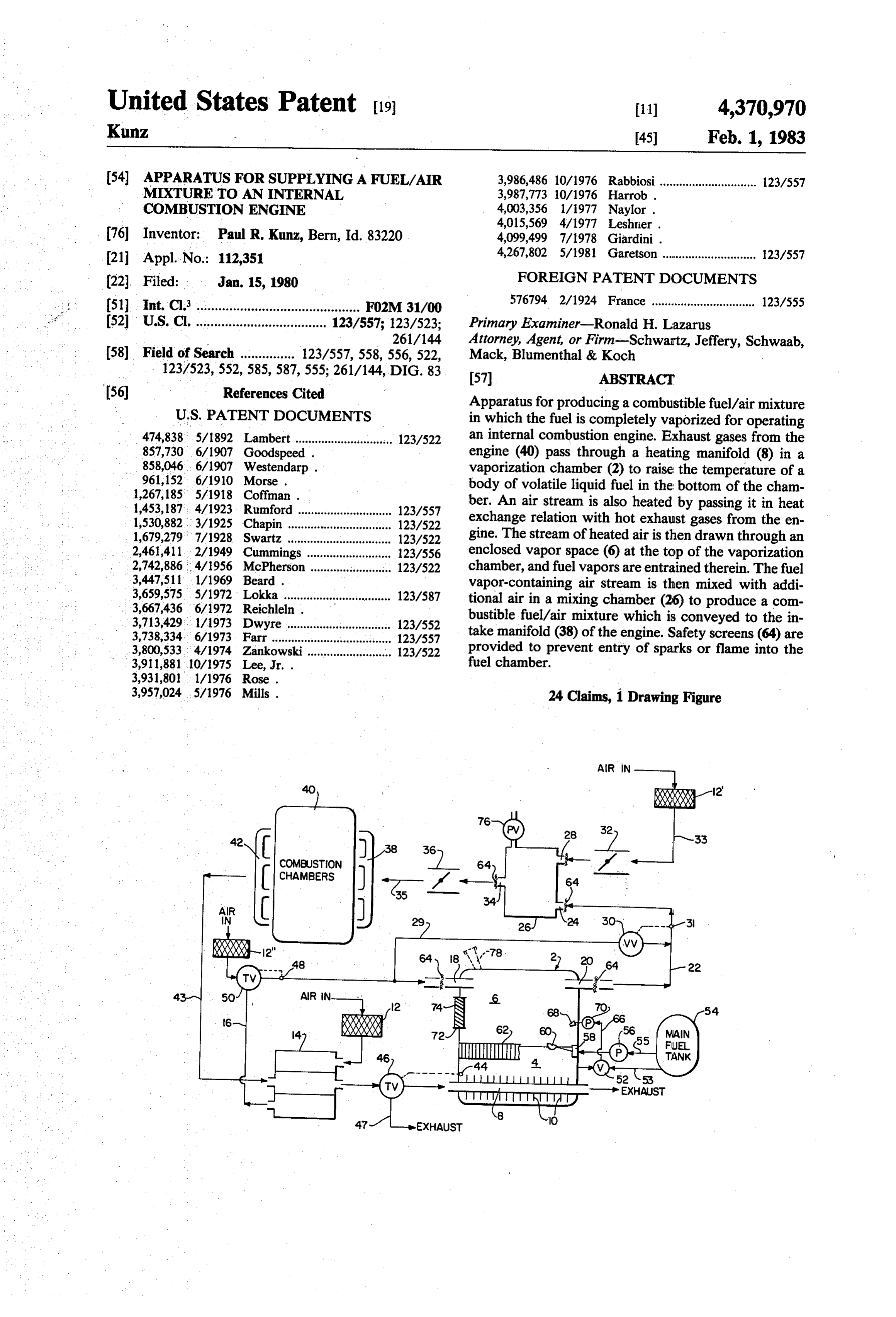
United States Patent (19) 11) 4,370,970 Kunz 45 Feb. 1, 1983 (54) APPARATUS FOR SUPPLYING A FUEL/AIR 3,986,486 10/1976 Rabbiosi.............................. 123/557 MIXTURE TO AN INTERNAL 3,987,773 10/1976 Harrob . COMBUSTON ENGINE 4,003,356 1/1977 Naylor.
76) Inventor: Paul R. Kunz, Bern, Id. 83220 4,099,499 7/1978 Giardini. 21 Appl. No.: 112,351 4,267,802 5/1981 Garetson ............................ 123/557 (22 Filed: Jan. 15, 1980 FOREIGN PATENT DOCUMENTS 51) Int. Cl. ............................................. F02M 31/00 576794 2/1924 France ................................ 123/555 52 U.S. C. .................................... 123/557; 123/523; Primary Examiner-Ronald H. Lazarus 261/144 Attorney, Agent, or Firm-Schwartz, Jeffery, Schwaab, 58) Field of Search ............... 123/557, 558,556, 522, Mack, Blumenthal & Koch 123/523,552, 585,587,555; 261/144, DIG. 83 57 ABSTRACT
Apparatus for producing a combustible fuel/air mixture
474,838.5/1892 Lambert .............................. 123/522 an internal combustion engine. Exhaust gases from the 857,730 6/1907 Goodspeed . engine (40) pass through a heating manifold (8) in a 858,046 6/1907 Westendarp . vaporization chamber (2) to raise the temperature of a 961,152 6/1910 Morse. body of volatile liquid fuel in the bottom of the cham 1,267,185 5/1918 Coffman. ber. An air stream is also heated by passing it in heat 1,453,187.4/1923 Rumford. ... 123/557 1,530,882.3/1925 Chapin ...... ... 123/522 exchange relation with hot exhaust gases from the en 1,679,2797/1928 Swartz .......... ... 123/522 gine. The stream of heated air is then drawn through an 2,461,411 2/1949 Cummings .... ... 123/556 enclosed vapor space (6) at the top of the vaporization 2,742,886 4/1956 McPherson ......................... 123/522 chamber, and fuel vapors are entrained therein. The fuel 3,447,511 1/1969 Beard . vapor-containing air stream is then mixed with addi 3,659,575 5/1972 Lokka ................................. 123/587 tional air in a mixing chamber (26) to produce a com 3,667,436 6/1972 Reichleln. bustible fuel/air mixture which is conveyed to the in 3,713,429. 1/1973 Dwyre...... ... 123/552 3,738,334 6/1973. Farr....... ... 123/557 take manifold (38) of the engine. Safety screens (64) are 3,800,5334/1974 Zankowski........................... 123/522 provided to prevent entry of sparks or flame into the 3,911,881 10/1975 Lee, Jr. . fuel chamber.
3,957,024.5/1976 Mills, 24 Claims, 1 Drawing Figure
AiR IN
COMUSTON
CHAMBERS
EXHAUST
utility V
- --> EXHAUST
Page 2
Drawing sheet — no readable text.
Page 3
carburetors today remain the principal means utilized to
APPARATUS FOR SUPPLYING A FUEL/AIR produce fuel/air mixtures for internal combustion en MIXTURE TO AN INTERNAL COMBUSTION gines, notwithstanding all of the known disadvantages ENGINE of such carburetors.
BACKGROUND OF THE INVENTION OBJECTS OF THE INVENTION 1. Field of the Invention Accordingly, it is an object of the present invention This invention relates to apparatus for producing to provide apparatus to replace the conventional carbu fuel/air mixtures for internal combustion engines. More retor.
particularly, the present invention relates to apparatus 10 Another object of the present invention is to provide in which the heat of exhaust gases from the engine is apparatus for producing a fuel/air mixture in which the utilized in an efficient manner to completely vaporize fuel is completely vaporized.
the fuel, thereby enabling production of an efficiently A further object of the present invention is to provide burning fuel/air mixture. apparatus which will increase the efficiency and econ 2. Description of the Prior Art 15 omy of operation of internal combustion engines. In a conventional carburetor, a stream of gasoline is Another object of the present invention is to provide aspirated into a draft of air in a venturi where it is dis apparatus for producing a fuel/air mixture which is persed into a mist of fine droplets. Despite years of useful in stationary and in mobile engines. development, the conventional carburetor is compara SUMMARY OF THE INVENTION tively inefficient. Theoretically, the droplets vaporize 20 to produce a gaseous fuel/air mixture. In actual prac tice, vaporization is often incomplete with the result byThese and other objects of the invention are achieved providing apparatus for supplying a fuel/air mixture that combustion is also incomplete, and unburned hy to an internal combustion engine comprising a fuel drocarbons pass into the exhaust and are wasted.
Numerous attempts have been made to develop alter 25 chamber comprising a lower portion for containing a native systems for producing fuel/air mixtures in which bodying an of volatile liquid fuel and an upper portion defin enclosed vapor space above said body of liquid complete volatilization will be achieved. It has been fuel; heating manifold means extending through said proposed to use the heat of the exhaust gases from the lower chamber portion for conducting hot exhaust engine to promote vaporization. For example see Giar dini, et. al., U.S. Pat. No. 4,099,499; Goodspeed, U.S. 30 gases therethrough in order to heat a body of volatile Pat. No. 857,730; and Coffman, U.S. Pat. No. 1,267,185, liquid fuel therein; means for drawing an air stream in which the fuel line is passed through the exhaust through said enclosed vapor space and entraining fuel conduit in order that the heat of the exhaust gases may vapors in said air stream; means for passing said air promote vaporization. Rose, U.S. Pat. No. 3,931,801, stream in heat exchange relation with hot exhaust gases and Reichhelm, U.S. Pat. No. 3,667,436, disclose sys 35 to raise the temperature of the air stream prior to draw tems in which the hot exhaust gases are passed into ing the air stream through said vapor space; means for direct contact with the fuel in order to promote vapori mixing said fuel vapor-containing air stream with addi zation. In the system of Reichhelm, the hot exhaust tional air to produce a combustible fuel/air mixture; gases are also passed into contact with the exterior of means for conveying said combustible fuel/air mixture the gasification chamber and preheated air may option 40 to a combustion chamber of an internal combustion ally be passed through the gasification chamber in order engine; and means for preventing entry of sparks or to cleanse the chamber. Leshner, et al., U.S. Pat. No. flame into said enclosed vapor space. 4,015,569, discloses a system in which volatile liquid BRIEF DESCRIPTION OF THE DRAWINGS fuel is passed through a chamber located in the exhaust conduit of an internal combustion engine and vaporized 45 The invention will be explained in further detail with by the heat of the exhaust gas after which the fumes are reference to the accompanying drawing which is a mixed with combustion air and fed to the engine. schematic representation of the apparatus of the inven Lee, U.S. Pat. No. 3,911,881, discloses a system in tion.
which a fuel/air mixture from a carburetor is passed through a vaporization chamber which is heated by 50 DETAILED DESCRIPTION EMBODIMENT
OF A PREFERRED
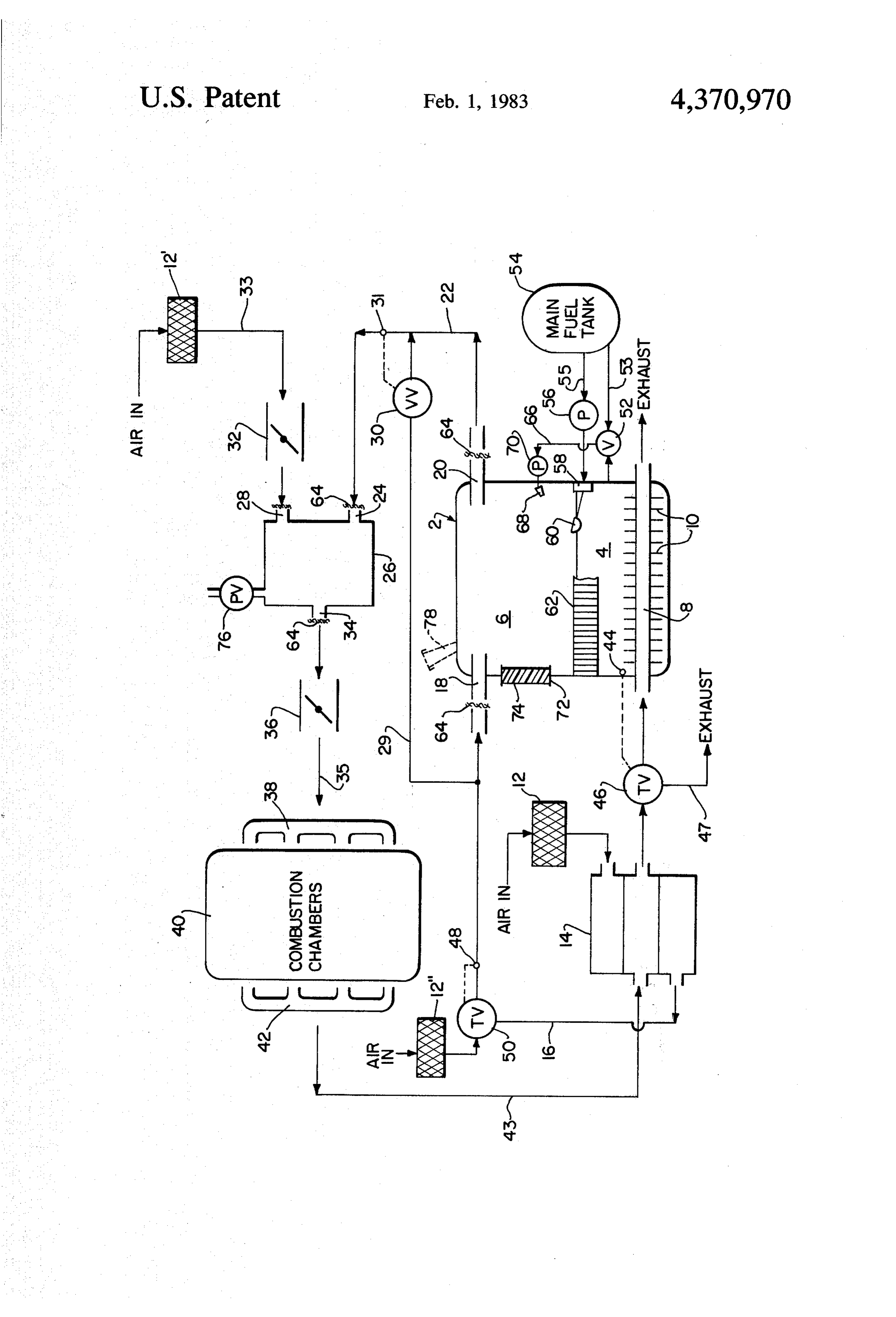
passing hot exhaust gases through an adjoining cham ber. Harrow, et. al., U.S. Pat. No. 3,987,773, and Mills, The accompanying FIGURE illustrates schemati U.S. Pat. No. 3,957,024, disclose systems in which a cally apparatus for producing a combustible fuel/air heat transfer fluid is used to convey heat from the hot mixture for an internal combustion engine according to exhaust gases to vaporize a liquid fuel in a stream of 55 the present invention. A fuel chamber 2 is provided combustion air. Naylor, U.S. Pat. No. 4,003,356, dis comprising a lower portion 4 for containing a body of closes a system for vaporizing a liquid motor fuel in an volatile liquid fuel, such as gasoline, and an upper por air-free environment by passing it in heat exchange tion 6 defining an enclosed vapor space. The walls of relation with the hot water from the engine cooling the fuel chamber must be sufficiently rigid to withstand system. Beard, U.S. Pat. No. 3,447,511, teaches the use a slight negative pressure, i.e., a pressure less than atmo of heat from exhaust gases to generate fuel from crude spheric, in the interior of the chamber. A heating mani oil. Morse, U.S. Pat. No. 961,152, and Westendarp, U.S. fold 8 extends through the lower chamber portion 4 Pat. No. 858,046, disclose vaporization of heavy hydro such that a body of liquid fuel therein will be in contact carbons, such as kerosene, by passing them in heat ex with the exterior of the manifold. Hot exhaust gases are change relation with hot exhaust gases after which the 65 passed through manifold 8, and heat from the gases is fuel vapors are mixed with combustion air. transferred to the liquid fuel, thereby raising the tem Despite the extensive efforts of the prior art to find a perature and the tendency of the fuel to evaporate, i.e., substitute for the conventional carburetor, conventional the vapor pressure of the fuel. If desired, fins 10 may be
Page 4
provided on manifold 8 in order to promote the transfer If desired, to control the temperature of the body of of heat between the manifold and the surrounding fuel. liquid fuel in lower chamber portion 4, a temperature In larger fuel tanks or chambers, the heating manifold sensor 44 may be provided in lower chamber portion 4 may advantageously take the form of a network of so as to be in contact with the body of liquid fuel. The parallel conduits, rather than a single conduit as illus 5 measured temperature determined by sensor 44 is trans trated in the drawing. This arrangement facilitates more mitted to a thermal valve 46 interposed between heat effective heat transfer to the body of liquid fuel. exchanger 14 and heating manifold 8. Valve 46 acts in In response to the motion of the engine, a stream of response to the measured temperature value to appor air is drawn through air filter 12 to a heat exchanger 14. tion the flow of hot exhaust gas between heating mani In exchanger 14, the temperature of the air is raised by 10 fold 8 and a diversion conduit 47. Initially, when the passing it in heat exchange relation with a hot exhaust body of liquid fuel in lower chamber portion 4 is cold, gas stream. The hot air stream passes through line 16 all of the exhaust gases are passed through heating man and enters vapor space 6 through inlet 18. The air ifold 8. As the temperature of the liquid fuel approaches stream there mixes with fuel vapors produced by the the desired value, a portion of the hot exhaust gases will combined action of the hot exhaust gas stream passing 15 be diverted away from heating manifold 8. If the tem through heating manifold 8 and the hot air stream. The perature of the liquid fuel becomes too great, all of the fuel vapor-containing air stream exits from vapor space exhaust gases will be channeled through diversion con 6 through outlet 20. The fuel vapor-containing air duit 47. In this way, the temperature of the liquid fuel in stream is conveyed through line 22 to inlet 24 of a mix the fuel chamber can be automatically controlled. De ing chamber 26. Simultaneously, a stream of supplemen 20 sirably, when the fuel is gasoline, the temperature of the tal air is drawn through air cleaner 12" and line 33 and liquid fuel will be maintained between about 70 F. and enters mixing chamber 26 through inlet 28. The fuel about 95° F., preferably between about 80 F. and about vapor-containing air stream entering through inlet 24 85 F. Somewhat higher temperatures may be required and the additional air stream entering through inlet 28 for less volatile fuels, such as diesel fuel. are intimately admixed as they pass through the mixing 25 A second temperature sensor 48 is interposed in line chamber. The amount of air entering the mixing cham 16 in the path of the hot air stream between heat ex ber through inlet 28 from line 33 is controlled by throt changer 14 and fuel chamber inlet 18 so as to measure tle valve 32. This may be a manually controlled valve or the temperature of the air stream. The measured tem it may be automatically controlled in the known fashion perature value is transmitted to a thermally responsive in response to engine operating conditions. By adjusting 30 valve 50. Ambient temperature air from air cleaner 12' throttle valve 32, the proportions of air and fuel vapor may also be introduced into line 16 through valve 50. in the ultimate mixture exiting mixing chamber 26 This valve acts in response to the measured temperature through outlet 34 can be controlled. Closing valve 32 to apportion the mix of heated air from the exchanger will produce a fuel-rich mixture and opening valve 32 and ambient air from the air cleaner. When the engine is will produce a lean fuel/air mixture. 35 first started, all of the air drawn into the fuel chamber The combustible fuel/air mixture then passes through comes from the heat exchanger in order to provide a line 35 and throttle valve 36 to the intake manifold 38 hot air stream as soon as possible. As the temperature of which in turn leads to the combustion chambers of the air stream reaches the desired level, valve 50 will internal combustion engine 40. The fuel/air mixture is open to admit a portion of ambient temperature air from burned in the combustion chambers to drive the engine. 40 the air cleaner to line 16 to maintain the proper tempera Hot exhaust gases left after the fuel/air mixture has been ture. When gasoline is utilized as the volatile liquid fuel, combusted are forced out of the combustion chambers the temperature of the air stream will desirably be main through exhaust manifold 42. The hot exhaust gases are tained between about 70 F. and about 105 F., prefera conveyed from the exhaust manifold via line 43 to ex bly between about 75 F. and about 90°F. If the temper changer 14 where they are passed in heat exchange 45 ature of the air stream starts to exceed about 110 F., the relation with an air stream in order to heat the air flow of air from the heat exchanger will be cut off and stream as previously described. After leaving exchanger all of the air entering the fuel chamber will be drawn 14, the hot exhaust gases then pass through heating through air cleaner 12'. It has been found that, when manifold 8 where they serve as previously described to the temperature of the air stream exceeds about 110' to heat a body of liquid fuel in the lower chamber portion 50 120 F., the more volatile components of the fuel are 4. After passing through heating manifold 8, the exhaust rapidly stripped away leaving an oily residue which gases are discharged to pollution control systems and/or remains in the fuel chamber.
muffler systems (not shown) as desired. As fuel from the body of liquid fuel in lower chamber The apparatus of the invention additionally may com portion 4 is evaporated and drawn off with the hot air prise means for selectively permitting a portion of the 55 stream, replacement fuel is provided from a main fuel hot air stream to bypass the fuel vaporization chamber. tank 54 through fuel supply line 55 by means of a pump In the illustrated embodiment, such means comprise a 56. A needle valve 58 operated by a float 60 serves to bypass line 29 extending between fuel chamber inlet line maintain a constant fuel level in lower chamber portion 16 and chamber outlet line 22. A vacuum-operated 4.
valve 30 is provided on line 29 and an associated pres 60 In stationary installations, the fuel chamber may sure sensor is disposed in line 22. As the speed of engine serve as the main fuel tank of the system. In such a case, 40 is increased, the negative pressure or vacuum in line fuel tank 54, line 55, pump 56, valve 58 and float 60 are 22 also increases. This is detected by sensor 31 which eliminated and replaced by a fill spout 78, shown in causes valve 30 to open, thereby allowing hot air from dotted lines at the top of fuel chamber 2. line 16 to bypass the fuel chamber through line 29, 65 In mobile installations, means are provided to prevent automatically producing a leaner fuel/air mixture and sloshing of the fuel in lower chamber portion 4. Such improving operating efficiency when the engine is ac means may take the form of a network of baffles which celerated. divide the surface of the body of liquid fuel into a large
Page 5
number of small areas. A preferred slosh-preventing to an auxiliary tank of volatile starting fluid instead of to means comprises a honeycomb matrix 62 providing a the main fuel tank.
plurality of vertically-oriented, hexagonal channels Fuel chamber 2 is also provided with means to relieve with open upper and lower faces. Matrix 62 is posi excessive pressures which may arise therein. In the tioned inside fuel chamber 2 so that its upper surface is illustrated embodiment, a short, broad conduit 72 is substantially even with or slightly above the surface of provided extending through the sidewall of fuel cham the body of liquid fuel. A portion of the matrix may be ber 2. Conduit 72 is closed with a plug 74 formed of cut out to permit free operation of float 60. For conve resilient material, such as rubber. At normal operating nience in illustration, the matrix is shown extending pressures, plug 74 provides a vapor-tight seal. If pres only part way across the fuel chamber, but it is under 10 sures within fuel chamber 2 rise to excessive levels, stood that in actual operation, the matrix will extend however, plug 74 will be ejected from conduit 72 to across as much of the surface of the body of liquid as vent the chamber and release the pressure. Although for possible. The anti-slosh baffle matrix is ordinarily un convenience of illustration only a single conduit and necessary in stationary installations. plug assembly has been shown in the drawing, it is It may also be noted that air stream inlet 18 and outlet 15 referred to use two such assemblies on opposite sides of 20 extend inwardly of the wall of fuel chamber 2. This the fuel chamber. It has been found that with two such arrangement prevents any fuel which may slosh up plugs, a fire ignited in the fuel chamber will be blown wardly along the wall of the fuel chamber, due to ex out as the plugs are expelled.
treme motion of the vehicle, from passing into the inlet 20 Mixing chamber 26 is provided with backfire relief or outlet. In the drawing, inlet 18 and outlet 20 are means. Desirably, such means may take the form of a shown aligned with each other in opposite walls of the pressure-relief valve 76. If the engine backfires, the fuel chamber, but it should be understood that they may pressures generated inside the mixing chamber will be be positioned in various locations and at varying angles exhausted harmlessly to the atmosphere through valve to accommodate installation requirements. The princi 76.
pal requirement to be kept in mind is that they should be 25 Numerous modifications of the illustrated embodi positioned so that the stream of air passing through the ment are possible. For example, check valves can be fuel chamber will not entrain droplets of unvaporized provided on line 22 and line 16 to prevent backflow of fuel. Ordinarily, this may be accomplished by position gases through the fuel chamber. The mixing chamber ing the inlet and outlet several inches above the level of could be provided with one or more baffles defining a the fuel. A distance of 3 to 4 inches has been found tortuous path therethrough in order to promote inti satisfactory in most instances. mate mixing of the fuel/air mixture from line 22 and the Fuel chamber inlet 18 and outlet 20 are covered by supplemental air from line 33. The three air cleaners 12, fine mesh metal screens 64. These screen members serve 12' and 12" could be combined into a single unit, possi as spark barriers to prevent sparks or flames from enter 35 bly with optional baffles defining separate sections for ing the fuel chamber 2. Similar barrier screens may be each system.
provided at inlets 24 and 28 and outlet 34 of mixing Importantly, in the apparatus of the invention, only chamber 26. The use of such barrier screens substan fuel vapors are picked up by the air stream as it passes tially reduces explosion hazards. through the fuel chamber. No droplets of liquid fuel are The apparatus of the invention also contains auxiliary 40 entrained in the air stream. Moreover, through the prin vaporization means which are used to cold-start the cipal purpose of screens 64 is to prevent passage of engine. The auxiliary vaporization means comprises a sparks, if a small amount of liquid were to become en fuel circulation line 66 communicating between the trained in the air stream, it would be separated out as the body of the liquid fuel in lower chamber portion 4 and air stream passed through the screen. Thus, only com a spray nozzle 68 disposed in the enclosed vapor space 45 pletely vaporized fuel is withdrawn from the fuel cham 6 just above the surface of the body of liquid fuel. A ber for incorporation in the fuel/air mixture. pump 70 is provided to convey a stream of fuel through As a result of the complete vaporization of the fuel in line 66 and out nozzle 68. The spray of fuel emanating the fuel/air mixture, as well as the infinite control of the from nozzle 68 agitates the body of fuel in the fuel richness or leanness of the mixture (fuel/air ratio) made chamber, thereby promoting vaporization and provid 50 possible by the apparatus of the invention, higher inter ing sufficient fuel vapors to start engine 40. Other agi nal combustion engine operating efficiencies may be tating means might also be utilized. Spray nozzle 68 achieved. For example, in tests of a prototype embodi should be positioned far enough beneath fuel chamber ment in a 1972 Chevrolet Vega automobile equipped inlet 18 and outlet 20 that fuel droplets will not become with a 140 cubic inch, four-cylinder engine under road entrained in the air stream passing through the fuel 55 conditions, a gasoline mileage of approximately 52 mpg chamber. has been achieved. Similarly, tests in a 1973 Chevrolet Fuel circulation line. 66 is further provided with a pickup truck equipped with a 350 cubic inch, eight-cyl valve 52 which also connects with an auxiliary fuel inder engine under road conditions have obtained a supply line 53 from the main fuel tank 54. Valve 52 is gasoline mileage of approximately 35 mpg. With the spring loaded to normally permit free flow of fuel original conventional carburetor, this truck only through line. 66 so that when pump 70 is activated, fuel achieved a gasoline mileage of approximately 14 mpg. from the lower portion of the fuel chamber is drawn Importantly, these improvements were achieved with into the circulation system. However, if the most vola out any drastic decrease in vehicle performance. tile components of the fuel in the fuel chamber have The foregoing embodiment and alternatives have been stripped away, valve 52 may be actuated to permit 65 been described solely as an illustration of the invention. fresh fuel from the main fuel tank to be drawn into the It is understood that modifications of the disclosed em recirculation system, thereby furnishing additional vol bodiment within the scope and spirit of the invention atiles for cold starting. Also, line 53 could be connected may occur to persons skilled in the art. Accordingly,
Page 6
the scope of the invention is to be determined with lower chamber portion for maintaining a constant fuel reference to the appended claims. level in said lower chamber portion. I claim: 10. Apparatus according to claim 1 wherein said 1. Apparatus for supplying a fuel/air mixture to an heating manifold means comprises a network of parallel internal combustion engine comprising: conduits extending through said lower chamber por (a) a fuel chamber comprising a lower portion for tion.
containing a body of volatile liquid fuel in a sub 11. Apparatus according to claim 1 wherein said stantially quiescent state and an upper portion de spark entry preventing means comprise fine metal mesh fining an enclosed vapor space free of liquid fuel screens interposed in the path of said air stream. during normal operation above said body of said 10 12. Apparatus according to claim 1 further compris liquid fuel; ing fin means on the exterior of said heating manifold (b) heating manifold means extending through said means for enhancing the transfer of heat from said hot lower chamber portion for conducting hot exhaust exhaust gases to said body of liquid fuel.
gases therethrough in order to heat a body of vola 15 13. Apparatus according to claim 1 further compris tile liquid fuel therein; ing screen means for preventing sparks or flame from (c) means comprising an inlet and an outlet opening entering said mixing means.
directly into said enclosed vapor space for drawing 14. Apparatus according to claim 13 further compris an air stream through said enclosed vapor space ing backfire relief means on said mixing means. and entraining fuel vapors in said air stream with 15. Apparatus according to claim 14 wherein said out said air stream passing through said body of 20 backfire relief means comprises a pressure relief valve liquid fuel and without liquid fuel being entrained communicating between the interior of said mixing in said air stream; means and the ambient atmosphere.
(d) means for passing said air stream in heat exchange 16. Apparatus according to claim 1 further compris relation with hot exhaust gases to raise the temper 25 ing means for controlling the amount of additional air ature of the air stream prior to drawing the air which is mixed with said fuel vapor-containing air stream through said vapor space; Stream.
(e) means for mixing said fuel vapor-containing air 17. Apparatus according to claim 16 wherein said stream with additional air to produce a combustible amount-controlling means is manually operated. fuel/air mixture; 30 18. Apparatus for supplying a fuel/air mixture to an (f) means for conveying said combustible fuel/air internal combustion engine comprising:
mixture to a combustion chamber of an internal (a) a fuel chamber comprising a lower portion for combustion engine; containing a body of volatile liquid fuel and an (g) means for preventing entry of sparks or flame into upper portion defining an enclosed vapor space said enclosed vapor space; and 35 above said body of liquid fuel; (h) means comprising two apertures located in oppo (b) heating manifold means extending through said site walls of said fuel chamber from each other, lower chamber portion for conducting hot exhaust each aperture communicating between said en gases therethrough in order to heat a body of vola closed vapor space and the ambient atmosphere, tile liquid fuel therein;
and each aperture being closed by a resilient blow 40 (c) means comprising an inlet and an outlet opening out plug ejectable from said aperture if the pressure directly into said enclosed vapor space for drawing in said chamber exceeds a predetermined level. an air stream through said enclosed vapor space 2. Apparatus according to claim 1 further comprising and entraining fuel vapors in said air stream with filter means for filtering said air stream prior to drawing out said air stream passing through said body of the air stream through said enclosed vapor space. 45 liquid fuel;
3. Apparatus according to claim 1 further comprising (d) means for passing said air stream in heat exchange air filter means for filtering said additional air prior to relation with hot exhaust gases to raise the temper mixing it with the fuel-containing air stream. ature of the air stream prior to drawing the air 4. Apparatus according to claim 1 further comprising stream through said vapor space; baffle means for preventing sloshing of said body of 50 (e) means for mixing said fuel vapor-containing air liquid fuel in said lower chamber portion. stream with additional air to produce a combustible 5. Apparatus according to claim 4 wherein said baffle fuel/air mixture;
means comprises a matrix of honeycomb cells having (f) means for conveying said combustible fuel/air open top and bottom faces. mixture to a combustion chamber of an internal 6. Apparatus according to claim 1 further comprising 55 combustion engine; and means for controlling the rate of flow of said combusti (g) means for selectively permitting a portion of said ble fuel/air mixture into said combustion chamber. hot air stream to bypass said fuel chamber in order 7. Apparatus according to claim 1 wherein said lower to produce a leaner fuel/air mixture. chamber portion comprises the principal fuel tank for 19. Apparatus according to claim 18 wherein said said internal combustion engine. 60 bypass permitting means is activated by a vacuum valve 8. Apparatus according to claim 1 further comprising responsive to decreases in the pressure in the outlet line means for supplying a body of volatile liquid fuel to said of the fuel chamber.
lower chamber portion. 20. Apparatus for supplying a fuel/air mixture to an 9. Apparatus according to claim 8 wherein said sup internal combustion engine comprising:
ply means comprises a fuel tank, a fuel line leading from 65 (a) a fuel chamber comprising a lower portion for said tank to said lower chamber portion, pump means containing a body of volatile liquid fuel and an for conveying fuel through said fuel line, and a float upper portion defining an enclosed vapor space operated valve at the outlet of said fuel line into said above said body of liquid fuel;
Page 7
(b) heating manifold means extending through said upper portion defining an enclosed vapor space lower chamber portion for conducting hot exhaust above said body of liquid fuel; gases therethrough in order to heat a body of vola (b) heating manifold means extending through said tile liquid fuel therein; lower chamber portion for conducting hot exhaust (c) means comprising an inlet and an outlet opening 5 gases therethrough in order to heat a body of vola directly into said enclosed vapor space for drawing tile liquid fuel therein;
an air stream through said enclosed vapor space (c) means comprising an inlet and an outlet opening and entraining fuel vapors in said air stream with directly into said enclosed vapor space for drawing out said air stream passing through said body of 1 O an air stream through said enclosed vapor space liquid fuel; and entraining fuel vapors in said air stream with (d) means for passing said air stream in heat exchange out said air stream passing through said body of liquid fuel;
relation with hot exhaust gases to raise the temper (d) means for passing said air stream in heat exchange ature of the air stream prior to drawing the air relation with hot exhaust gases to raise the temper stream through said vapor space; 15 ature of the air stream prior to drawing the air (e) means for mixing said fuel vapor-containing air stream through said vapor space; stream with additional air to produce a combustible (e) means for mixing said fuel vapor-containing air fuel/air mixture; stream with additional air to produce a combustible (f) means for conveying said combustible fuel/air fuel/air mixture;
mixture to a combustion chamber of an internal 20 (f) means for conveying said combustible fuel/air combustion engine; and mixture to a combustion chamber of an internal (g) means for sensing the temperature of said body of combustion engine; and liquid fuel in said lower chamber portion and a (g) means for measuring the temperature of said air thermal valve operable in response to the measured stream prior to entry into said fuel chamber and temperature to increase or decrease the amount of 25 thermal valve means responsive to the measured hot exhaust gases passing through said heating temperature for selectively admixing ambient air manifold in order to maintain the temperature of with the hot air passed in heat exchange relation said body of liquid fuel between about 70 F. and with the hot exhaust gases in order to control the about 95° F. during operation of the engine. temperature of the air stream.
21. Apparatus according to claim 20 wherein the temperature 23. Apparatus according to claim 22 wherein the temperature of said body of liquid fuel is maintained vapor space isofmaintained said air stream entering said enclosed at between about 70 F. and between about 80 F. and about 85 F. about 105 F. during operation of said engine. 22. Apparatus for supplying a fuel/air mixture to an 24. Apparatus according to claim 23 wherein the internal combustion engine comprising: 35 temperature of said air stream is maintained between (a) a fuel chamber comprising a lower portion for about 75 F. and about 90' F.
containing a body of volatile liquid fuel and an sk k k is ak
Provenance
- Collection
- Cited prior art
- Original PDF
- patentimages.storage.googleapis.com →
- Filed
- 1980-01-15
- Pages
- 7
- Method
- pdftotext (the PDF's own text layer) + pdftoppm 300dpi page scans
- Source
- Google Patents bibliographic record
- Granted
- 1983-02-01
- Inventors
- Paul R. Kunz
- Transcribed from
- patentimages.storage.googleapis.com →