patent · US3730668
Combustion method of gas burners for suppressing the formation of nitrogen oxides and burner apparatus for practicing said method
1 May 1973
Page 1 — bibliographic record
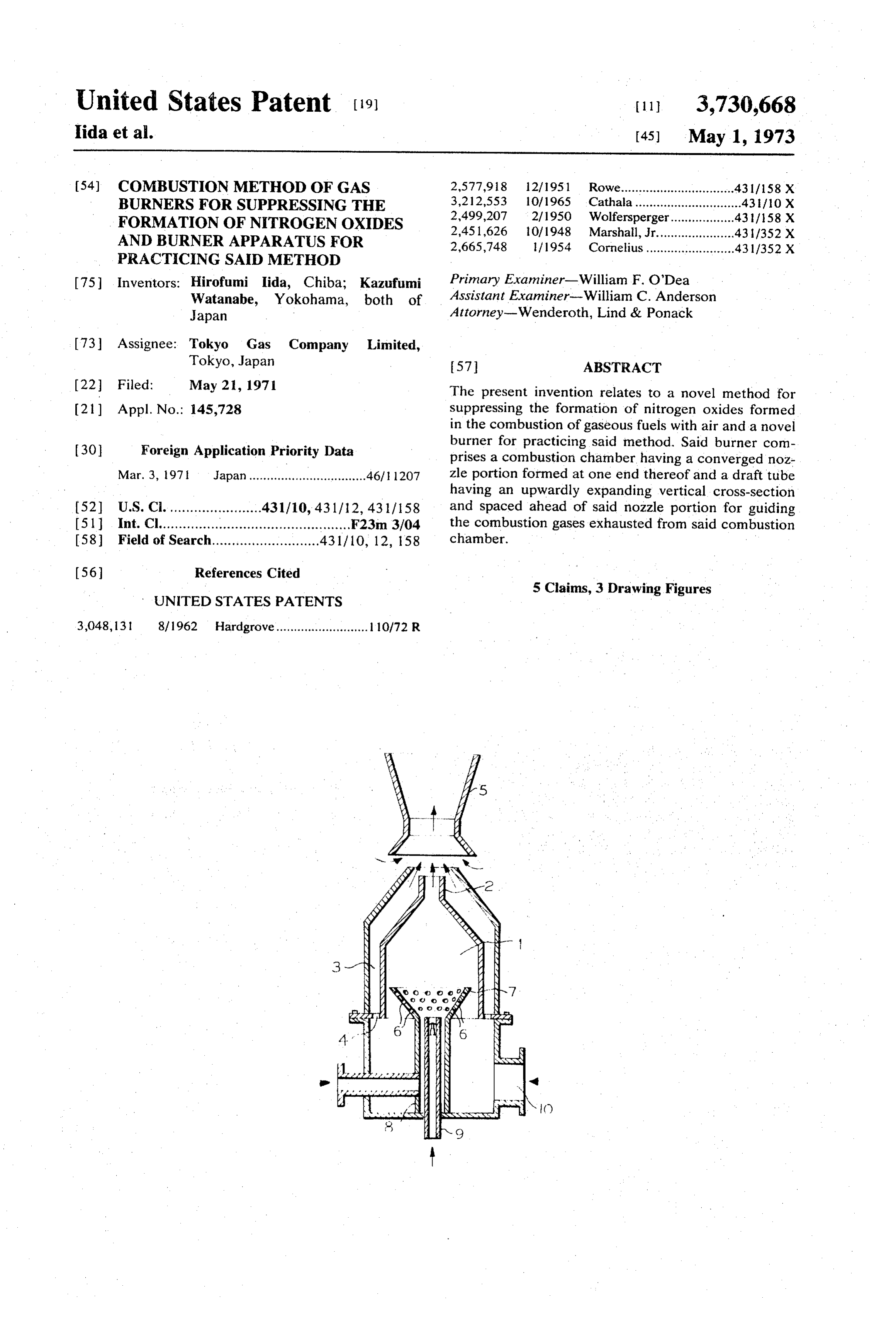
United States Patent (19) 11, 3,730,668 Iida et al. (45) May 1, 1973 54) COMBUSTION METHOD OF GAS 2,577,918 12/1951 Rowe................................431/158 X BURNERS FOR SUPPRESSING THE 3,212,553 10/1965 Cathala ..............................43 if 10 X FORMATION OF NITROGEN OXDES 2,499,207 2/1950 Wolfersperger.................. 431/158 X AND BURNER APPARATUS FOR 2,451,626 10/1948 Marshall, Jr...................... 431/352 X 2,665,748 l/1954 Cornelius .........................43 1/352 X
PRACTICING SAD METHOD
75 Inventors: Hirofumi Iida, Chiba; Kazufumi Primary Examiner-William F. O'Dea Watanabe, Yokohama, both of Assistant Examiner-William C. Anderson
Japan - Attorney-Wenderoth, Lind & Ponack 73) Assignee: Tokyo Gas Company Limited,
Tokyo, Japan 57 ABSTRACT 22 Filed: May 21, 1971 The present invention relates to a novel method for (21) Appl. No.: 145,728 suppressing the formation of nitrogen oxides formed in the combustion of gaseous fuels with air and a novel (30) Foreign Application Priority Data burner for practicing said method. Said burner com prises a combustion chamber having a converged noz
Mar. 3, 1971 Japan................................. 46/ 1207 zle portion formed at one end thereof and a draft tube having an upwardly expanding vertical cross-section 52) U.S. Ci........................431/10, 431/12, 431/158 and spaced ahead of said nozzle portion for guiding (51 Int. Cl................................................ F23m 3/04 the combustion gases exhausted from said combustion 58) Field of Search........................... 431/10, 12, 158 chamber.
5 Claims, 3 Drawing Figures
UNITED STATES PATENTS
3,048, 131 8/1962 Hardgrove.......................... 110/72 R
Page 2
Drawing sheet — no readable text.
Page 3
COMBUSTION METHOD OF GAS BURNERS FOR - secondary air passage 3 is closed in the vicinity of the SUPPRESSING THE FORMATION OF NITROGEN nozzle portion 2, the secondary air passage holes 11 are OXOES AND BURNERAPPARATUSFOR formed in chamber 1. In such a case, the cooling air PRACTICING SAD METHOD stream 12 is formed on the side of the nozzle portion 2 which cools the nozzle portion 2 made from a metallic
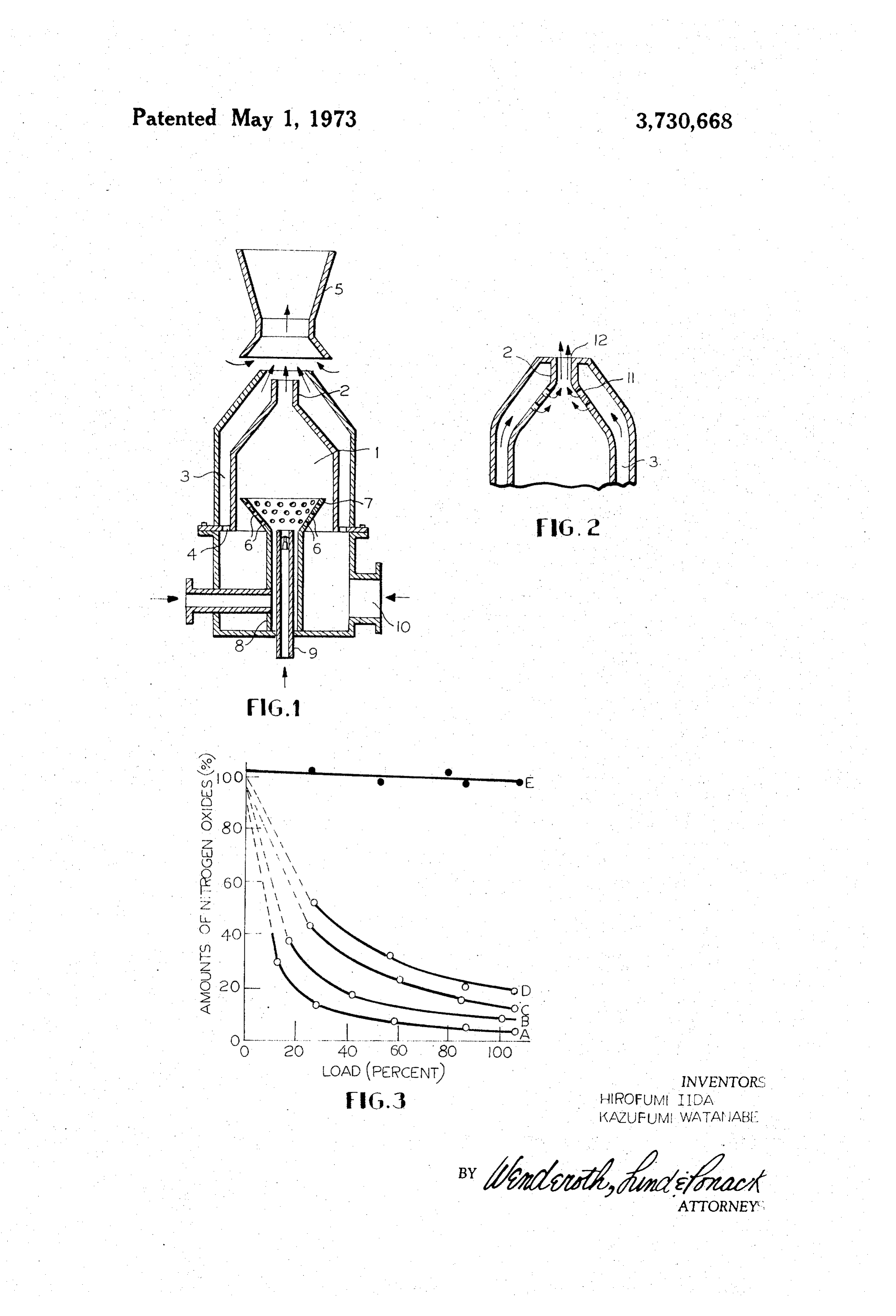
This invention relates to a method for gas used in material. The quantity of the secondary air passing boilers, various industrial heating furnaces, dryers, through the secondary air passageway 3 is 10 - 40 per ovens, etc., whereby the amount of nitrogen oxides cent of the theoretical air requirement and determined contained in combustion gases are minimized; and a 10 by the secondary air passage holes 4. Reference nu burner apparatus for practicing said method. meral 5 designates a draft tube for drawing the com As the major factors which have influence on the bustion gas in the furnace by the jetting combustion amounts of nitrogen oxides contained in the com gases stream. The draft tube 5 has an upwardly expand bustion gases, there are generally considered flame ing vertical cross-section so as to enhance the drawing temperature, excess air ratio and cooling velocity of 15 effect of the combustion gases in the furnace, and is flame. In this regard, various methods have been em suitably spaced ahead of the nozzle portion 2. The ployed in conventional fixed-type combustion ap combustion chamber 1, the secondary air passageway 3 paratus for suppressing the generation of nitrogen ox and the draft tube 5 are respectively made from a ides, which are broadly classified into the following two metallic or refractory material. Reference numeral 6 types: Namely, in one type, the combustion gases are 20 designates an air flow equalizing plate having a large recirculated to lower the flame temperature, and in the number of primary air passage holes 7 formed therein other type the amount of air required for the com and connected integrally with a gas feed pipe 8, and 9 bustion is fed slowly so as to control the combustion designates a pilot burner concentrically mounted in rate. However, the former method has disadvantages in said gas feed pipe 8.
that the stability of the flame is low, means must be pro 25 With the construction described above, air required vided for recycling the combustion gases and thermal for combustion is supplied through an air inlet port 10 efficiency is low. On the other hand, the latter method and part of the air, i.e., a quantity of air 60-90 percent has the disadvantage that, since the mixing ratio of fuel of the theoretical air requirement, is introduced in to gas and air tends to be inconsistent, the excess air ratio the combustion chamber 1 through the primary air must be made slightly greater than with the ordinary 30 passage combustion method, with the result that the formation 6. The holes 7 formed in the air flow equalizing plate of nitrogen oxides is further promoted. It has further passageway 3 throughpart remaining of the air enters the air disadvantages in that means must be provided for sup and reaches the end extremity of theairnozzle the secondary passage holes 4 plying the secondary air and in that the combustion after passing through said air passageway 3. Aportion fuel
gas
The present invention has been achieved based on an isfeed fed into the combustion chamber 1 from the fuel gas pipe 8, and intensely mixed with the primary air entirely novel concept of suppressing the formation of and burned therein. Since the combustion chamber 1 nitrogen oxides in the oxidation of fuels such as has the converged nozzle portion 2 as stated above, the hydrocarbons, e.g., natural gas, etc., with air, which as load in the combustion used here, includes air containing more or less than the about 5,000 - 10,000 xchamber
usual amount of oxygen. According to the invention, bustion gases contain some10amount Kcal/m hr. The con of unburned fuel the disadvantages of the conventional combustion gas because only the primary air is introduced into the methods can be completely eliminated and the thermal combustion chamber 1, and is exhausted from the noz efficiency can be markedly enhanced.
The present invention will be described in detail at aportion 45 zle 2 to the outside of the combustion chamber high velocity of 50 - 200 m/sec. The combustion hereinafter with reference to the accompanying draw gases exhausted at such a high velocity are mixed with ing which illustrate an embodiment of the invention. In the secondary air supply which has cooled the outer the drawings:
FIG. 1 is a vertical cross-sectional view illustrating an parallel or at an angle to chamber wall of the combustion 1, while moving in the secondary air supply, and embodiment of the burner apparatus according to the 50 present invention; enter the draft tube 5, ahead of the nozzle portion 2, FIG. 2 is an enlarged-sectional view illustrating while undergoing secondary combustion. When the another embodiment of the nozzle portion, and combustion gases are mixed with the secondary air FIG. 3 is a diagram graphically showing the com 55 supply and are burned, a negative pressure is created bustion characteristic of the burner apparatus with around the nozzle portion 2 in accordance with the respect to the amounts of nitrogen oxides generated energy of jetting combustion gases and the combustion during combustion. gases within the furnace are drawn under the effect of In FIG. 1, reference numeral 1 designates a com said negative pressure as indicated by the arrows. The bustion chamber having a converged nozzle portion 2. jetting combustion gases and the combustion gases in The cross-sectional area of the combustion chamber 1 60 the furnace are mixed so quickly that the high tempera is 5 - 20 times the cross-sectional area of the nozzle ture, high velocity combustion gases, containing some portion 2. Reference numeral 3 designates a secondary amount of unburned fuel gas, are increasingly ex air passageway formed around the combustion hausted and cooled, and the unburned fuel gas con chamber 1. One end of the secondary air passageway 3 65 tained therein is completely burned. In this case, since is provided secondary air passage holes 4 and the other the amount of the jetting combustion gases is as large as end thereof is open or closed in the vicinity of the noz 10 - 200 times that of the accompanying gases within zle portion 2. With reference to FIG. 2, in case the the furnace, though variable, depending upon the flow
Page 4
resistance in the furnace, an extremely large amount of formation of nitrogen oxides, due to a combination of combustion gas circulates in the furnace. factors including the fact that the primary combustion Characteristic curve A in the chart of FIG. 3 is a fuel-rich combustion, that the combustion is ef represents the result of combustion obtained by the fected stepwise by the primary and secondary com method and apparatus of the instant invention. It will bustions, that the secondary combustion reaction is be apparent from this characteristic curve that accord carried out while the temperature of the fuel gas is ing to the invention, that the amounts of nitrogen ox being lowered by combustion of the gases in the fur ides can be substantially decreased as compared with nace, that the residence time of the combustion gases the conventional burner apparatus, the characteristic 10 within the furnace is long, and that the length of the of which is represented by a curve E. flame is short. Further, as will be understood from FIG. Although in the embodiment described above, the 2, while in the conventional burner apparatus the secondary air passageway 3 is formed around the com amounts of nitrogen oxides formed corresponding to bustion chamber 1 and the draft tube 5 is provided the load factor (the amounts of nitrogen oxide per unit ahead of the nozzle portion 2, the amounts of nitrogen 5 quantity of heat) are substantially constant, in the oxides formed can be substantially decreased as com burner apparatus of the instant invention an increasing pared with the conventional burner E, by employing load factor results in an increasing velocity of the com the combustion chamber 1 only of the construction bustion gases jetting from the nozzle portion 2 and described without providing said secondary air hence in an increasing amount of the gases being passageway 3 and said draft tube 5. In this case, the 20 withdrawn from the combustion chamber, so that the theoretical quantity of air for combustion is introduced rate of formation of nitrogen oxides is lowered. into the combustion chamber 1 in its entirety but the According to the invention, as described above, it is cross-sectional area ratio between the nozzle portion 2 possible not only to substantially decrease the amounts and the combustion chamber 1 must be made smaller of nitrogen oxides formed, but also to improve the heat and the residence time of the air in the combustion 25 transmission rate, to make the temperature distribution chamber 1 must be made shorter than in the case of within the furnace uniform without providing any spe providing the secondary air passageway 3, so that the cial means, and to reduce the size of or eliminate the combustion may not be completed within said com combustion chamber of a furnace. Thus, by practicing bustion chamber. The combustion gases containing the invention, the general heating apparatus can be some amount of unburned fuel gas are exhausted from 30 simplified.
the nozzle portion 2 at a high velocity. The combustion What is claimed is:
gases jetting from the nozzle portion 2 suck and are 1. A combustion method for suppressing the forma mixed with the combustion gases within the furnace, tion of nitrogen oxides issuing from gas burners, com whereby the amount thereof is increased and the tem 35 prising introducing the theoretical quantity of air for perature thereof is lowered, and the unburned fuel gas combustion into a combustion chamber in its entirety, contained therein is consumed in the secondary com said combustion chamber being formed with a nozzle bustion. In such case, the amount of the gases sucked portion and said combustion chamber having a cross from the furnace is somewhat smaller than in the sectional area 5-20 times that of said nozzle portion, preceding case because the air is not fed stepwise and 40 burning 60-90 percent of a fuel gas in said combustion the draft tube 5 is not provided. However, as will be ob chamber, exhausting the combustion gases containing vious from a curve D in FIG. 3, the amounts of nitrogen unburned fuel gas at a high velocity through said nozzle oxides formed are very much smaller than in case of the portion and burning the unburned fuel gas completely conventional burner E. Curve B in FIG. 3 represents outside the burner apparatus by providing means the combustion characteristics of a burner apparatus in 45 cooperating with said nozzle portion for drawing the which the draft tube 5 is provided ahead of the com combustion gases in the furnace therefrom by said bustion chamber 1 but the secondary air passageway 3 combustion gases jetting from said nozzle portion. is not provided, similar to the preceding case. In this 2. A combustion method for suppressing the forma case, the secondary air is not supplied but, since the tion of nitrogen oxides issuing from gas burners, ac amount of the gases withdrawn from the combustion SO cording to claim 1, wherein a secondary air supply in a chamber 1 is increased by the existence of the draft quantity of 10 - 40 percent of the theoretical quantity tube 5, the effect of suppressing the formation of of air for combustion is passed along the outer wall of nitrogen oxides is greater than in the case of the burner said combustion chamber and the unburned fuel gas apparatus comprising only the combustion chamber 1. 55 contained in the combustion gases jetting from said Curve C in FIG. 3 represents the combustion charac nozzle port is completely burned by said secondary air teristics of a burner apparatus in which the secondary outside the burner apparatus.
air passageway 3 is provided around the combustion 3. A burner apparatus so designed as to suppress the chamber 1 but the draft tube 5 is not provided ahead of formation of nitrogen oxides, comprising a combustion said combustion chamber. In this case, the amount of chamber having a converged nozzle portion formed at the combustion gases withdrawn from the furnace is 60 one end thereof, said combustion chamber having a smaller than in case of the first-mentioned case but, cross-sectional area 5-20 times that of said nozzle por since the secondary air supply is through the secondary tion and a draft tube having an upwardly expanding air passageway 3 and is used for the secondary com vertical cross-section and spaced ahead of said nozzle bustion, the amounts of nitrogen oxides formed can be 65 portion for guiding the combustion gases exhausted substantially decreased. from said combustion chamber. It will be understood, after all, that the present inven 4. A burner apparatus so designed as to suppress the tion achieves a remarkable effect in suppressing the formation of nitrogen oxides, according to claim 3,
Page 5
wherein a secondary air passageway is formed around wherein one end of the secondary air passage is closed said combustion chamber with one end thereof open in in the vicinity of the nozzle portion and the secondary the vicinity of said nozzle portion. air passage holes are formed in the combustion 5. A burner apparatus so designed as to suppress the chamber in the vicinity of said nozzle portion. formation of nitrogen oxides, according to claim 4, sk sk ck sk sk
Provenance
- Collection
- Cited prior art
- Original PDF
- patentimages.storage.googleapis.com →
- Filed
- 1971-05-21
- Pages
- 5
- Method
- pdftotext (the PDF's own text layer) + pdftoppm 300dpi page scans
- Source
- Google Patents bibliographic record
- Granted
- 1973-05-01
- Inventors
- H Iida; K Watanabe; Tokyo Gas Co Ltd
- Transcribed from
- patentimages.storage.googleapis.com →