patent · US4955351
Vapor-accelerated combustion fuel system
11 September 1990
Page 1 — bibliographic record
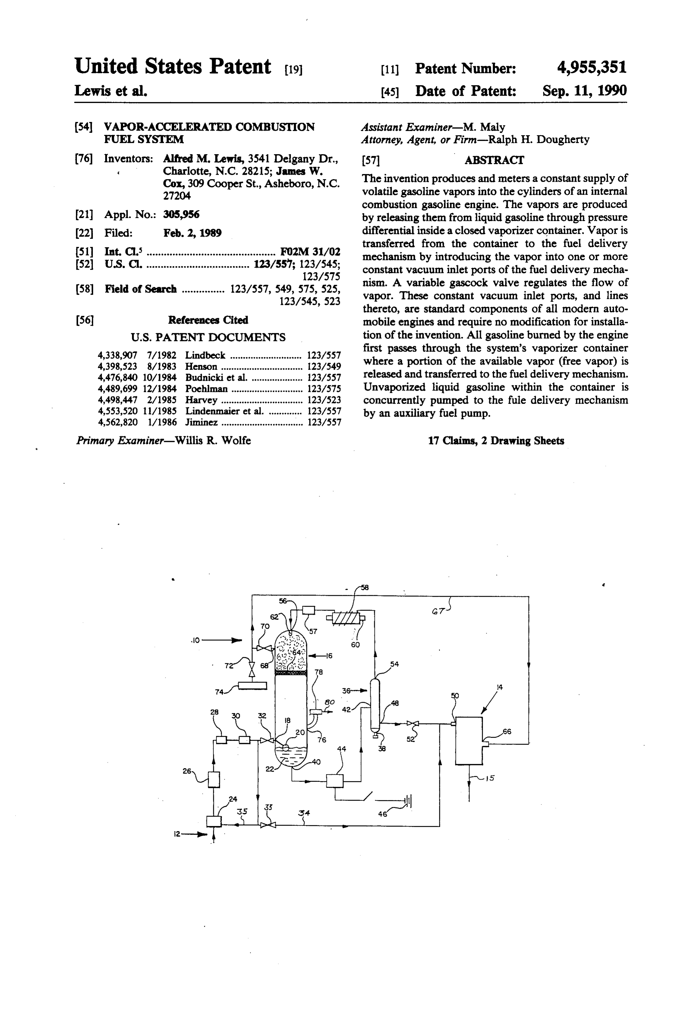
United States Patent (19) (11 Patent Number: 4,955,351 Lewis et al. (45) Date of Patent: Sep. 11, 1990 (54) WAPOR-ACCELERATED COMBUSTON Assistant Examiner-M. Maly FUEL SYSTEM Attorney, Agent, or Firm-Ralph H. Dougherty (76) Inventors: Alfred M. Lewis, 3541 Delgany Dr., (57 ABSTRACT Charlotte, N.C. 28215; James W. The invention produces and meters a constant supply of Cox, 309 Cooper St., Asheboro, N.C. volatile gasoline vapors into the cylinders of an internal
combustion gasoline engine. The vapors are produced 21) Appl. No.: 305,956 by releasing them from liquid gasoline through pressure 22 Filed: Feb. 2, 1989 differential inside a closed vaporizer container. Vapor is transferred from the container to the fuel delivery 51 Int. C. ............................................ FO2M 31/02 mechanism by introducing the vapor into one or more (52) U.S. C. .................................... 123/557; 123/545; constant vacuum inlet ports of the fuel delivery mecha 123/575 nism. A variable gascock valve regulates the flow of (58 Field of Search ............... 123/557, 549, 575,525, vapor. These constant vacuum inlet ports, and lines
thereto, are standard components of all modern auto (56) References Cited mobile engines and require no modification for installa
4,338,907 7/1982 Lindbeck ............................ 123/557 first passes through the system's vaporizer container 4,398,523 8/1983 Henson .............. ... 123/549 where a portion of the available vapor (free vapor) is 4,476,840 10/1984 Budnicki et all ... 123/557 released and transferred to the fuel delivery mechanism. 4,489,699 12/1984 Poehlman. ... 123/575 Unvaporized liquid gasoline within the container is 4,498,447 2/1985 Harvey ...... ... 123/523 concurrently pumped to the fule delivery mechanism 4,553,520 1 1/1985 Lindenmaie - - -- - - - - -- 123/557 by an auxiliary fuel pump.
4,562,820 l/1986 Jiminez ................................ 123/557
Primary Examiner-Willis R. Wolfe 17 Claims, 2 Drawing Sheets
Page 2
Drawing sheet — no readable text.
Page 3
Drawing sheet — no readable text.
Page 4
WAPOR-ACCE LERATED COMBUSTON FUEL
SYSTEM ISSUE
BACKGROUND OF THE INVENTION 5 4,398,523 Henson 08-16-83 Fuel Conservation Device 1. Field of the Invention 4,476,840 Budnicki et al. 10-16-84 Evaporation Chamber For Fuel Delivery
The present invention generally relates to systems System producing combustible vapors from a portion of the 4,483,304 Yokoi et al. 11-20-84 Fuel Vaporizer For gasoline admitted into the cylinders of an internal com Internal Combustion bustion engine, and more particularly, to such systems 10 Engines with gasoline pre-heating and vaporizing devices. 4,494,516 Covey, Jr. 01-22-85 Carburetor/Vaporizer
2. Description of the Prior Art et al. Generation. Of A The combustion characteristics within the cylinders Defined Fuel of an internal combustion engine change greatly with 5 Vaporwair Mixture the addition of sufficient amounts of vapor. As used 4,562,820 Jininez 01-07-86 Cavitation-Producing herein, the term "fuel delivery mechanism' means a Carburetion Apparatus And Method mechanism: for delivering fuel to the cylinders of an 4,448,173 Abe et al. 05-15-84 Fuel Evaporator internal combustion engine, including, but not limited to, a carburetor-based delivery mechanism or a fuel 20 injection-based delivery mechanism. Typically, with a Harvey and Henson bear some functional similarity spray of fine droplets of gasoline entering the cylinder, to the present invention. They both cover devices spe cifically directed toward increasing fuel efficiency in an which is the case with all standard fuel delivery mecha internal nisms, combustion proceeds in a chain reaction from the combustion engine and reducing exhaust pollut ignition point at the spark gap. The droplets nearest this 25 ants. Other patents have issued for vaporizer inventions, point ignite, heat up, expand, and ignite other droplets. including Abe et al., Budnicki et al., Yokoi et al., Although this happens very rapidly, there is not enough Covey, Jr., Harvey, Lindenmaier et al., and Jiminez. time in the fraction of a second when the piston is at the The typical function of these devices is to improve top of the compression stroke for the combustion to engine to the efficiency by delivering gasoline vapor directly carburetor.
spread entirely across the head of the cylinder and burn 30 all of the droplets of gasoline completely. This results in Several key features characterize the present inven fuel continuing to burn in the expanding space created tion and distinguish it from the patents listed above. as the piston moves back down the cylinder. This is First, it utilizes a spray means and a fine wire mesh usually referred to as afterburning, and it produces within a vaporizer container to vaporize the gasoline several deleterious effects both inside and outside the 35 and separate the vapor from the liquid gasoline. Second, engine (e.g., reduced engine power and performance, the heating component is separate and external to the increased engine wear due to loss of cylinder lubrica container. It may be a heat exchanger using heat from tion, accumulation of carbon and sludge deposits the engine coolant or an electric heating element, but throughout the engine, and increased toxic exhaust "water heat' is the preferred method. Third, vapor is emissions). However, when a sufficient amount of gaso transferred from the vaporizer container directly to one line vapors are introduced into the cylinder along with or more constant vacuum inletsstandard components of the gasoline droplets, afterburning is essentially elimi all modern engines. No secondary carburetor or any nated. This is because the vapors act as a medium for modification of the engine is required. Fourth, the con accelerating combustion across the head of the cylinder tainer has an atmospheric air inlet so that there cannot instantly while the piston is still at the top of the com 45 be any dangerous build-up of pressure or vacuum pression stroke. The gasoline is burned more quickly within the container. Finally, both the vaporizer con and completely resulting in more power and reduced tainer and the fuel delivery mechanism are supplied harmful emissions. Gasoline is not a uniform substance, from the same fuel circuit, permitting continuous re but a mixture of many different complex hydrocarbon plenishment of volatile gasoline components. molecules, some of which are very volatile while others 50 SUMMARY OF THE INVENTION will become volatile only at extremely high tempera tures which could not be safely maintained. Because of The invention produces and meters a constant supply this, only a portion of the total amount of vapor that can of volatile gasoline vapors into the cylinders of an inter be produced from a given quantity of gasoline can be nal combustion gasoline engine. The vapors are pro utilized. In the present invention a fresh supply of gaso 55 duced by releasing them from liquid gasoline through line enters the vaporizer container continually while pressure differential inside a closed vaporizer container. volatile and non-volatile material are removed. Volatile Vapor is transferred from the container to the fuel de and non-volatile material remain in approximately the livery mechansim by introducing the vapor into one or same proportion at all times. more constant vacuum inlet ports of the fuel delivery The applicants are aware of the following U.S. Pa 60 mechansim. A variable gascock valve regulates the tents concerning gasoline pre-heating and vaporizing flow of vapor. These constant vacuum inlet ports, and devices: lines thereto, are standard components of all modern automobile engines and require no modification for
ISSUE installation of the invention. All gasoline burned by the
U.S. Pat. No. INVENTOR DATE TITLE 65 engine first passes through the system's vaporizer con 4,498,447 Harvey 02-12-85 Gasoline Vaporizer tainer where a portion of the available vapor (free va For Internal por) is released and transferred to the fuel delivery
Combustion Engine mechanism. Unvaporized liquid gasoline within the
Page 5
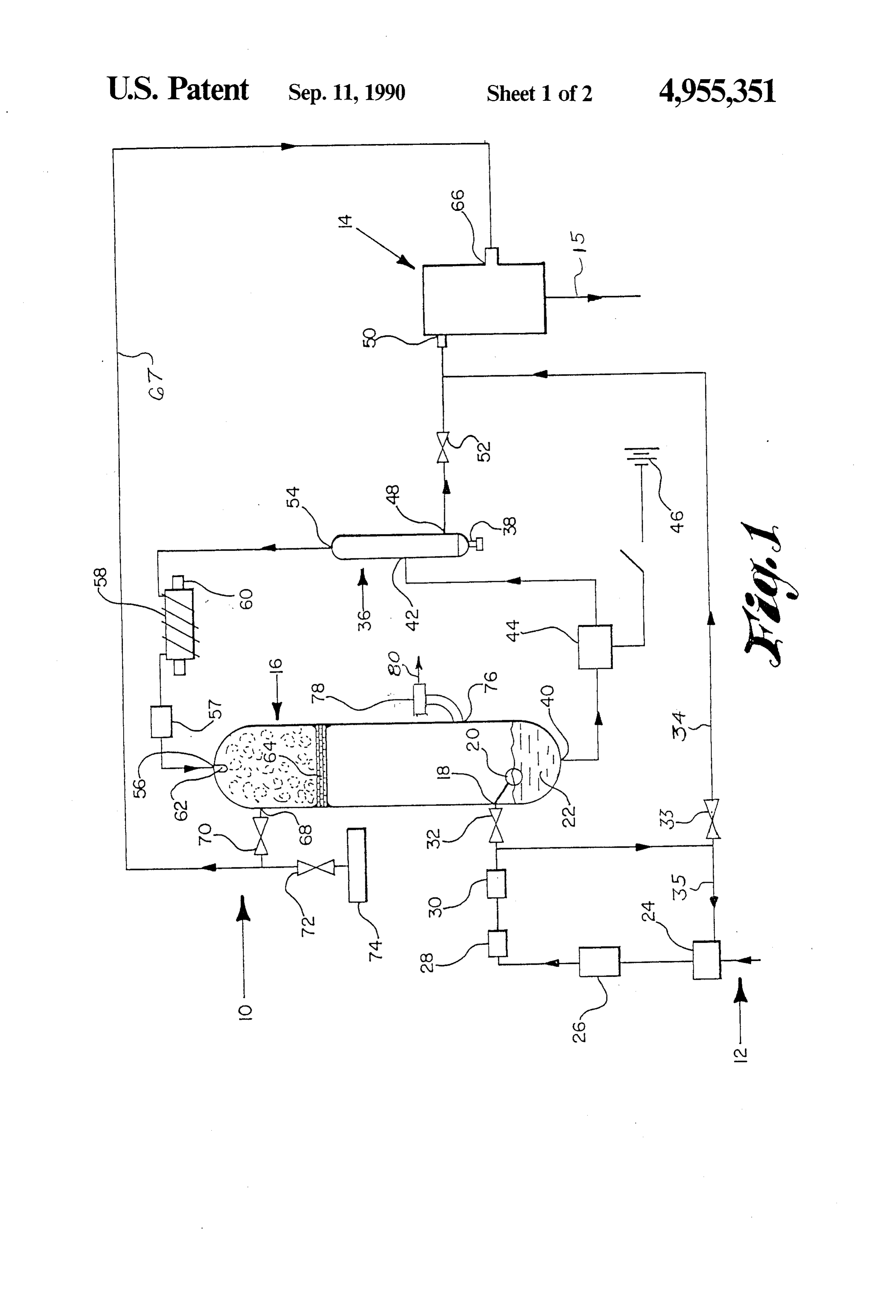
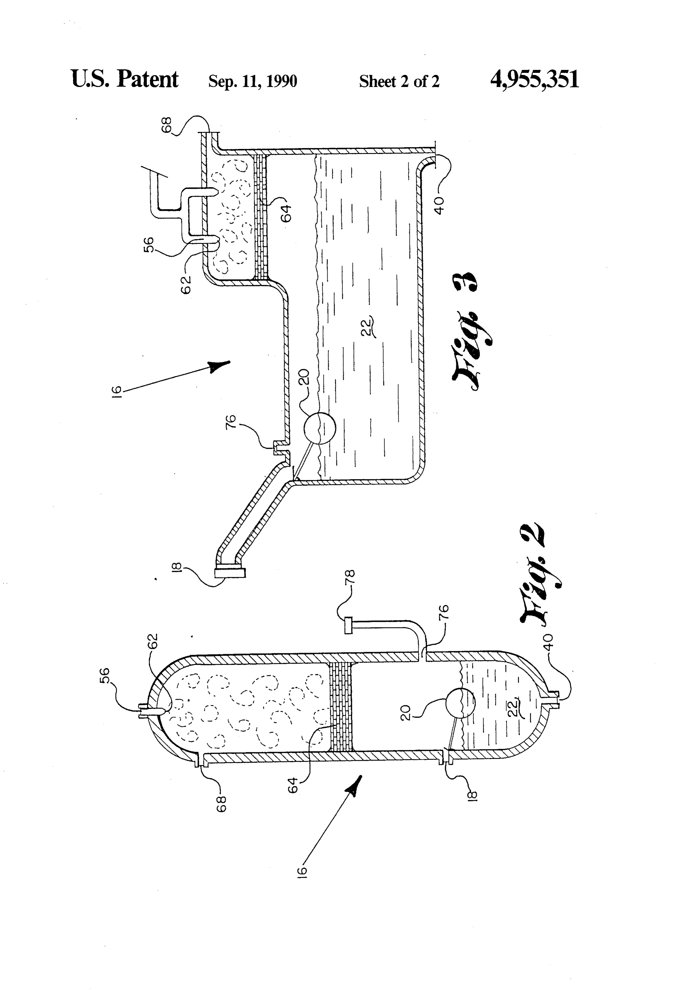
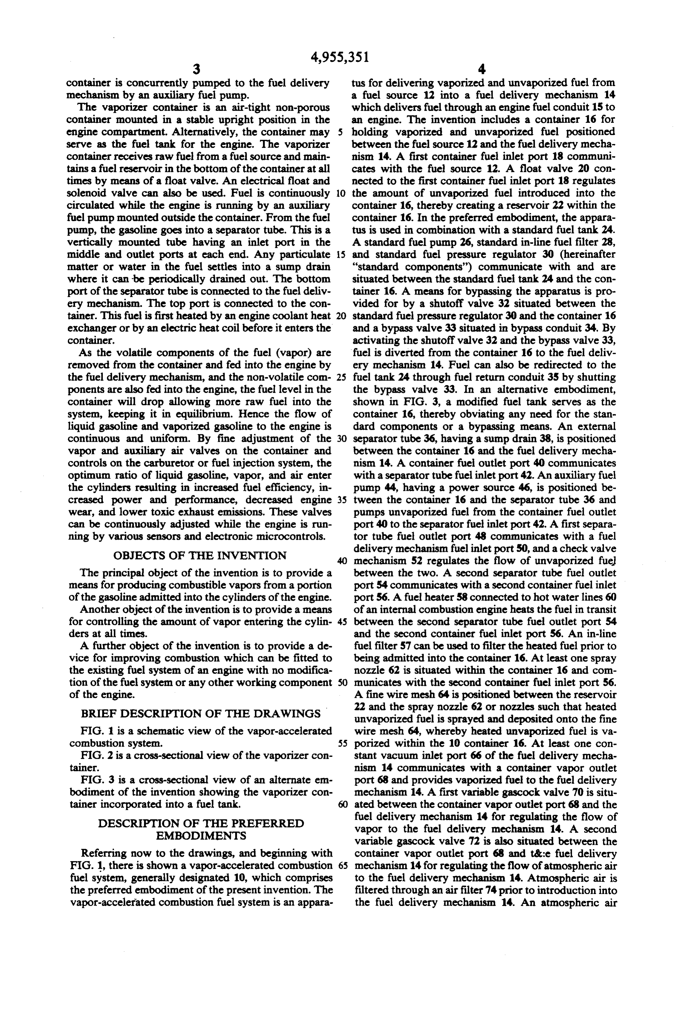
container is concurrently pumped to the fuel delivery tus for delivering vaporized and unvaporized fuel from mechanism by an auxiliary fuel pump. a fuel source 12 into a fuel delivery mechanism 14 The vaporizer container is an air-tight non-porous which delivers fuel through an engine fuel conduit 15 to container mounted in a stable upright position in the an engine. The invention includes a container 16 for engine compartment. Alternatively, the container may holding vaporized and unvaporized fuel positioned serve as the fuel tank for the engine. The vaporizer between the fuel source 12 and the fuel delivery mecha container receives raw fuel from a fuel source and main nism 14. A first container fuel inlet port 18 communi tains a fuel reservoir in the botton of the container at all cates with the fuel source 12. A float valve 20 con times by means of a float valve. An electrical float and nected to the first container fuel inlet port 18 regulates solenoid valve can also be used. Fuel is continuously O the amount of unvaporized fuel introduced into the circulated while the engine is running by an auxiliary container 16, thereby creating a reservoir 22 within the fuel pump mounted outside the container. From the fuel container 16. In the preferred embodiment, the appara pump, the gasoline goes into a separator tube. This is a tus is used in combination with a standard fuel tank 24. vertically mounted tube having an inlet port in the A standard fuel pump 26, standard in-line fuel filter 28, middle and outlet ports at each end. Any particulate 5 and standard fuel pressure regulator 30 (hereinafter matter or water in the fuel settles into a sump drain "standard components') communicate with and are where it can be periodically drained out. The bottom situated between the standard fuel tank 24 and the con port of the separator tube is connected to the fuel deliv tainer 16. A means for bypassing the apparatus is pro ery mechanism. The top port is connected to the con vided for by a shutoff valve 32 situated between the tainer. This fuel is first heated by an engine coolant heat 20 standard fuel pressure regulator 30 and the container 16 exchanger or by an electric heat coil before it enters the and a bypass valve 33 situated in bypass conduit 34. By container. activating the shutoff valve 32 and the bypass valve 33, As the volatile components of the fuel (vapor) are fuel is diverted from the container 16 to the fuel deliv removed from the container and fed into the engine by ery mechanism 14. Fuel can also be redirected to the the fuel delivery mechanism, and the non-volatile con 25 fuel tank 24 through fuel return conduit 35 by shutting ponents are also fed into the engine, the fuel level in the the bypass valve 33. In an alternative embodiment, container will drop allowing more raw fuel into the shown in FIG. 3, a modified fuel tank serves as the system, keeping it in equilibrium. Hence the flow of container 16, thereby obviating any need for the stan liquid gasoline and vaporized gasoline to the engine is dard components or a bypassing means. An external continuous and uniform. By fine adjustment of the 30 separator tube 36, having a sump drain 38, is positioned vapor and auxiliary air valves on the container and between the container 16 and the fuel delivery mecha controls on the carburetor or fuel injection system, the nism 14. A container fuel outlet port 40 communicates optimum ratio of liquid gasoline, vapor, and air enter with a separator tube fuel inlet port 42. An auxiliary fuel the cylinders resulting in increased fuel efficiency, in pump 44, having a power source 46, is positioned be creased power and performance, decreased engine 35 tween the container 16 and the separator tube 36 and wear, and lower toxic exhaust emissions. These valves pumps unvaporized fuel from the container fuel outlet can be continuously adjusted while the engine is run port 40 to the separator fuel inlet port 42. A first separa ning by various sensors and electronic microcontrols. tor tube fuel outlet port 48 communicates with a fuel OBJECTS OF THE INVENTION delivery mechanism fuel inlet port 50, and a check valve mechanism 52 regulates the flow of unvaporized fuel
The principal object of the invention is to provide a between the two. A second separator tube fuel outlet means for producing combustible vapors from a portion port 54 communicates with a second container fuel inlet of the gasoline admitted into the cylinders of the engine. port 56. A fuel heater 58 connected to hot water lines 60 Another object of the invention is to provide a means of an internal combustion engine heats the fuel in transit for controlling the amount of vapor entering the cylin 45 between the second separator tube fuel outlet port 54 ders at all times. and the second container fuel inlet port 56. An in-line A further object of the invention is to provide a de fuel filter 57 can be used to filter the heated fuel prior to vice for improving combustion which can be fitted to being admitted into the container 16. At least one spray the existing fuel system of an engine with no modifica nozzle 62 is situated within the container 16 and com tion of the fuel system or any other working component SO municates with the second container fuel inlet port 56. of the engine. A fine wire mesh 64 is positioned between the reservoir BRIEF DESCRIPTION OF THE DRAWINGS 22 and the spray nozzle 62 or nozzles such that heated unvaporized fuel is sprayed and deposited onto the fine
FIG. 1 is a schematic view of the vapor-accelerated wire mesh 64, whereby heated unvaporized fuel is va combustion system. 55 porized within the 10 container 16. At least one con FIG. 2 is a cross-sectional view of the vaporizer con stant vacuum inlet port 66 of the fuel delivery mecha tainer. nism 14 communicates with a container vapor outlet FIG. 3 is a cross-sectional view of an alternate em port 68 and provides vaporized fuel to the fuel delivery bodiment of the invention showing the vaporizer con mechanism 14. A first variable gascock valve 70 is situ tainer incorporated into a fuel tank. ated between the container vapor outlet port 68 and the DESCRIPTION OF THE PREFERRED fuel delivery mechanism 14 for regulating the flow of EMBODIMENTS vapor to the fuel delivery mechanism 14. A second variable gascock valve 72 is also situated between the
Referring now to the drawings, and beginning with container vapor outlet port 68 and t&:e fuel delivery FIG. 1, there is shown a vapor-accelerated combustion 65 mechanism 14 for regulating the flow of atmospheric air fuel system, generally designated 10, which comprises to the fuel delivery mechanism 14. Atmospheric air is the preferred embodiment of the present invention. The filtered through an air filter 74 prior to introduction into vapor-accelerated combustion fuel system is an appara the fuel delivery mechanism 14. An atmospheric air
Page 6
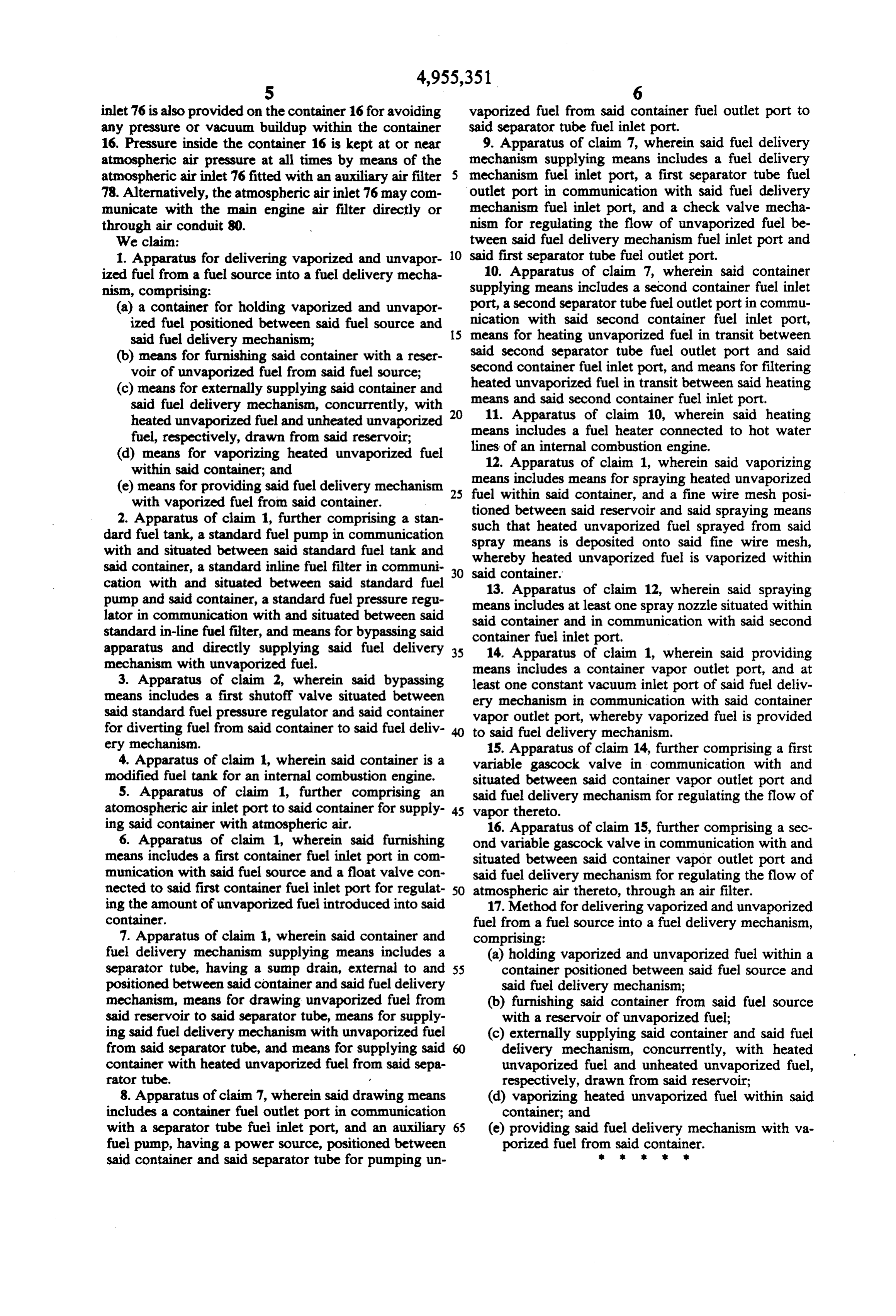
inlet 76 is also provided on the container 16 for avoiding vaporized fuel from said container fuel outlet port to any pressure or vacuum buildup within the container said separator tube fuel inlet port. 16. Pressure inside the container 16 is kept at or near 9. Apparatus of claim 7, wherein said fuel delivery atmospheric air pressure at all times by means of the mechanism supplying means includes a fuel delivery mechanism fuel inlet port, a first separator tube fuel atmospheric air inlet 76 fitted with an auxiliary air filter 78. Alternatively, the atmospheric air inlet 76 may com outlet port in communication with said fuel delivery municate with the main engine air filter directly or mechanism fuel inlet port, and a check valve mecha through air conduit 80. nism for regulating the flow of unvaporized fuel be We claim: tween said fuel delivery mechanism fuel inlet port and 1. Apparatus for delivering vaporized and unvapor O said first separator tube fuel outlet port. ized fuel from a fuel source into a fuel delivery mecha 10. Apparatus of claim 7, wherein said container nism, comprising: supplying means includes a second container fuel inlet (a) a container for holding vaporized and unvapor port, a second separator tube fuel outlet port in commu ized fuel positioned between said fuel source and 15 nication with said second container fuel inlet port, said fuel delivery mechanism; means for heating unvaporized fuel in transit between (b) means for furnishing said container with a reser said second separator tube fuel outlet port and said voir of unvaporized fuel from said fuel source; second container fuel inlet port, and means for filtering (c) means for externally supplying said container and heated unvaporized fuel in transit between said heating said fuel delivery mechanism, concurrently, with 20 means and said second container fuel inlet port. heated unvaporized fuel and unheated unvaporized means 11. Apparatus of claim 10, wherein said heating includes a fuel heater connected to hot water fuel, respectively, drawn from said reservoir; lines of an internal combustion engine. (d) means for vaporizing heated unvaporized fuel 12. Apparatus of claim 1, wherein said vaporizing within said container; and means includes means for spraying heated unvaporized (e) means for providing said fuel delivery mechanism 25 fuel within said container, and a fine wire mesh posi with vaporized fuel from said container. tioned between said reservoir and said spraying means 2. Apparatus of claim 1, further comprising a stan such that heated unvaporized fuel sprayed from said dard fuel tank, a standard fuel pump in communication spray means is deposited onto said fine wire mesh, with and situated between said standard fuel tank and whereby heated unvaporized fuel is vaporized within said container, a standard inline fuel filter in communi 30 said container.
cation with and situated between said standard fuel 13. Apparatus of claim 12, wherein said spraying pump and said container, a standard fuel pressure regu means includes at least one spray nozzle situated within lator in communication with and situated between said said container and in communication with said second standard in-line fuel filter, and means for bypassing said container fuel inlet port.
apparatus and directly supplying said fuel delivery 35 14. Apparatus of claim 1, wherein said providing mechanism with unvaporized fuel.
3. Apparatus of claim 2, wherein said bypassing means includes a container vapor outlet port, and at least one constant vacuum inlet port of said fuel deliv means includes a first shutoff valve situated between ery mechanism in communication with said container said standard fuel pressure regulator and said container vapor outlet port, whereby vaporized fuel is provided for diverting fuel from said container to said fuel deliv to said fuel delivery mechanism. ery mechanism. 15. Apparatus of claim 14, further comprising a first 4. Apparatus of claim 1, wherein said container is a variable gascock valve in communication with and modified fuel tank for an internal combustion engine. situated between said container vapor outlet port and 5. Apparatus of claim 1, further comprising an said fuel delivery mechanism for regulating the flow of atomospheric air inlet port to said container for supply 45 vapor thereto.
ing said container with atmospheric air. 16. Apparatus of claim 15, further comprising a sec 6. Apparatus of claim 1, wherein said furnishing ond variable gascock valve in communication with and means includes a first container fuel inlet port in com situated between said container vapor outlet port and munication with said fuel source and a float valve con said fuel delivery mechanism for regulating the flow of nected to said first container fuel inlet port for regulat 50 atmospheric air thereto, through an air filter. ing the amount of unvaporized fuel introduced into said 17. Method for delivering vaporized and unvaporized container. fuel from a fuel source into a fuel delivery mechanism, 7. Apparatus of claim 1, wherein said container and comprising:
fuel delivery mechanism supplying means includes a (a) holding vaporized and unvaporized fuel within a separator tube, having a sump drain, external to and 55 container positioned between said fuel source and positioned between said container and said fuel delivery said fuel delivery mechanism; mechanism, means for drawing unvaporized fuel from (b) furnishing said container from said fuel source said reservoir to said separator tube, means for supply with a reservoir of unvaporized fuel; ing said fuel delivery mechanism with unvaporized fuel (c) externally supplying said container and said fuel from said separator tube, and means for supplying said delivery mechanism, concurrently, with heated container with heated unvaporized fuel from said sepa unvaporized fuel and unheated unvaporized fuel, rator tube. respectively, drawn from said reservoir; 8. Apparatus of claim 7, wherein said drawing means (d) vaporizing heated unvaporized fuel within said includes a container fuel outlet port in communication container; and with a separator tube fuel inlet port, and an auxiliary 65 (e) providing said fuel delivery mechanism with va fuel pump, having a power source, positioned between porized fuel from said container. said container and said separator tube for pumping un
Provenance
- Collection
- Cited prior art
- Original PDF
- patentimages.storage.googleapis.com →
- Filed
- 1989-02-02
- Pages
- 6
- Method
- pdftotext (the PDF's own text layer) + pdftoppm 300dpi page scans
- Source
- Google Patents bibliographic record
- Granted
- 1990-09-11
- Inventors
- Alfred M. Lewis; James W. Cox
- Transcribed from
- patentimages.storage.googleapis.com →