patent · US5317876
Sound wave operated energy corverter for producing different forms of movement
7 June 1994
Page 1 — bibliographic record
United States Patent (19) 11 Patent Number: 5,317,876 Nakagawa et al. 45) Date of Patent: Jun. 7, 1994 54). SOUND WAVE OPERATED ENERGY 2,608,623 8/1952 Cutler et al. . CORVERTER FOR PRODUCING 2,616,984 11/1952 Paré . DFFERENT FORMS OF MOVEMENT 3,027,876 4/1962 Strick . 3,182,457 5/1965 Sato et al. ............................. 60/.532 75) Inventors: Katsumi Nakagawa, Tsuchiura; 3,511,050 5/1970 Taberner . Yasuo Kuwabara, Nagoya; Koji 5,145,333 9/1992 Smith .
Nishida, Anjo, all of Japan FOREIGN PATENT DOCUMENTS 73) Assignee: Aisin Seiki Kabushiki Kaisha, Kariya, 69.5722 11/1979 U.S.S.R. . Japan 1100435 6/1984 U.S.S.R. .
21 Appl. No.: 995,680 Primary Examiner-Edward K. Look (22 Filed: Dec. 23, 1992 Assistant Examiner-Hoang Nguyen Attorney, Agent, or Firm-Burns, Doane, Swecker & (30) Foreign Application Priority Data Mathis
Dec. 26, 1991 JP Japan .................................. 3-345031 57 ABSTRACT 51 Int, C. .............................................. F15B 21/12 An energy converter for converting a sound energy 52 U.S.C. .................................. 60/.532; 91/DIG. 1 into a kinetic energy is comprised of a source device for 58) Field of Search ......................... 60/532,519,389; radiating the sound energy, and a body having a cover 416/6, 223R;91/DIG. 1, DIG. 4, 1; 92/5 R member for absorbing the sound energy and a reflecting (56) References Cited member mounted thereon with the cover member in such a manner that the sound energy after passing
Re. 28,434 5/1975 Olsen ..................................... 60/.532 ber so as to be tangential thereto. 2,111,036 3/1938 Wippel .................................. 60/.532 2,181,120 1 1/1939 Dake . 9 Claims, 9 Drawing Sheets
Page 2
Drawing sheet — no readable text.
Page 3
Drawing sheet — no readable text.
Page 4
Drawing sheet — no readable text.
Page 5
Drawing sheet — no readable text.
Page 6
Drawing sheet — no readable text.
Page 7
Drawing sheet — no readable text.
Page 8
Drawing sheet — no readable text.
Page 9
Drawing sheet — no readable text.
Page 10
Drawing sheet — no readable text.
Page 11
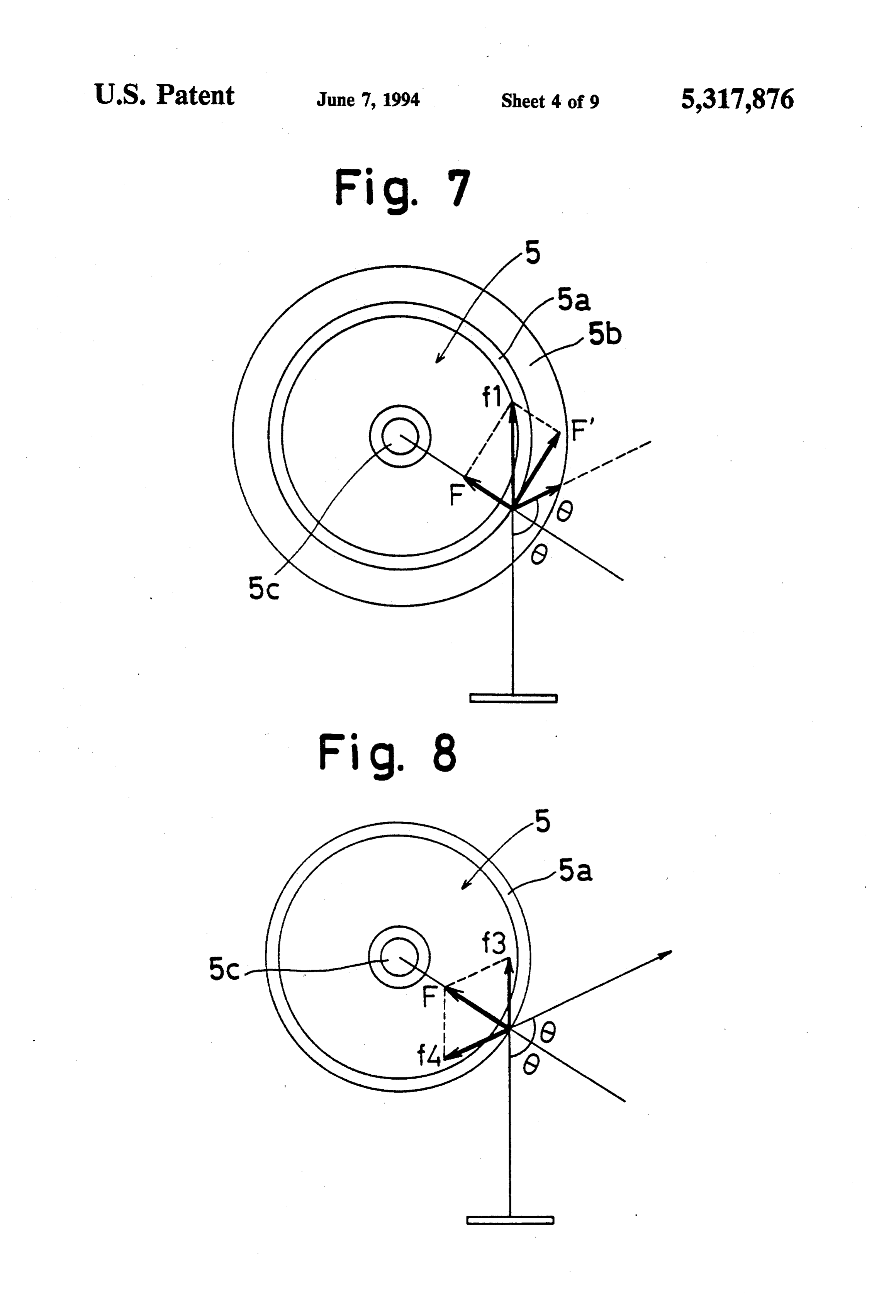
FIGS. 7 and 8 show a brief operation principle of the
SOUND WAVE OPERATED ENERGY device in FIG. 1;
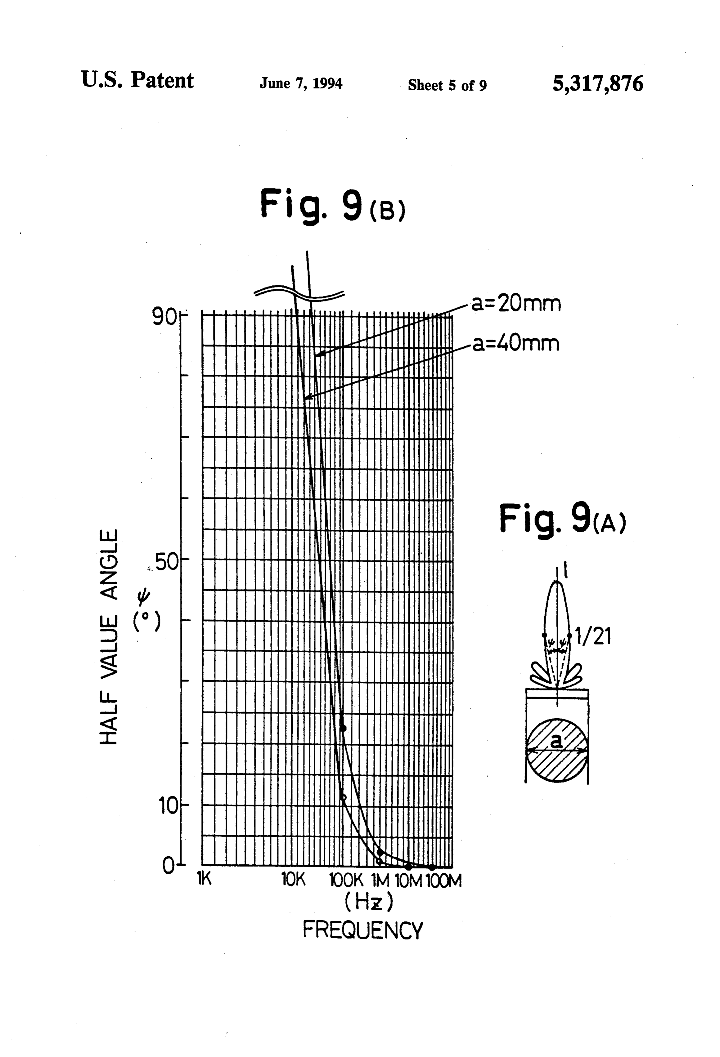
CORVERTER FOR PRODUCING DIFFERENT FIG. 9(A) shows a schematic operation principle of FORMS OF MOVEMENT the device in FIG. 1;
FIG.9(B) shows a graphic operation principle of the
BACKGROUND OF THE INVENTION device in FIG. 1;
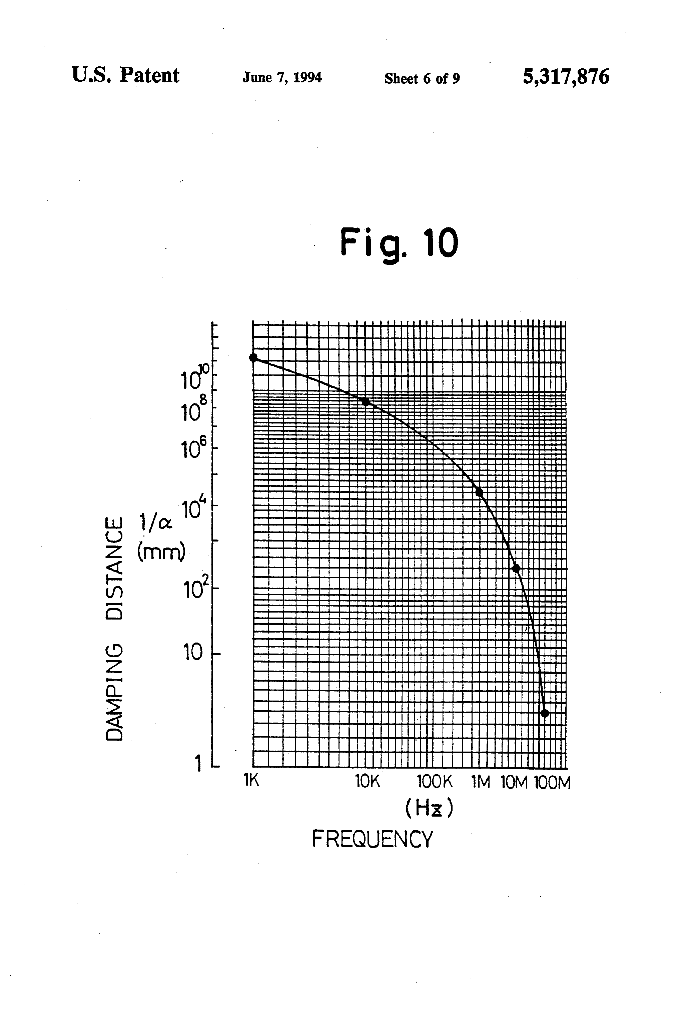
The present invention relates to an energy converter, FIG. 10 shows another graphic operation principle of and in particular to a sound wave operated energy con the device in FIG. 1;
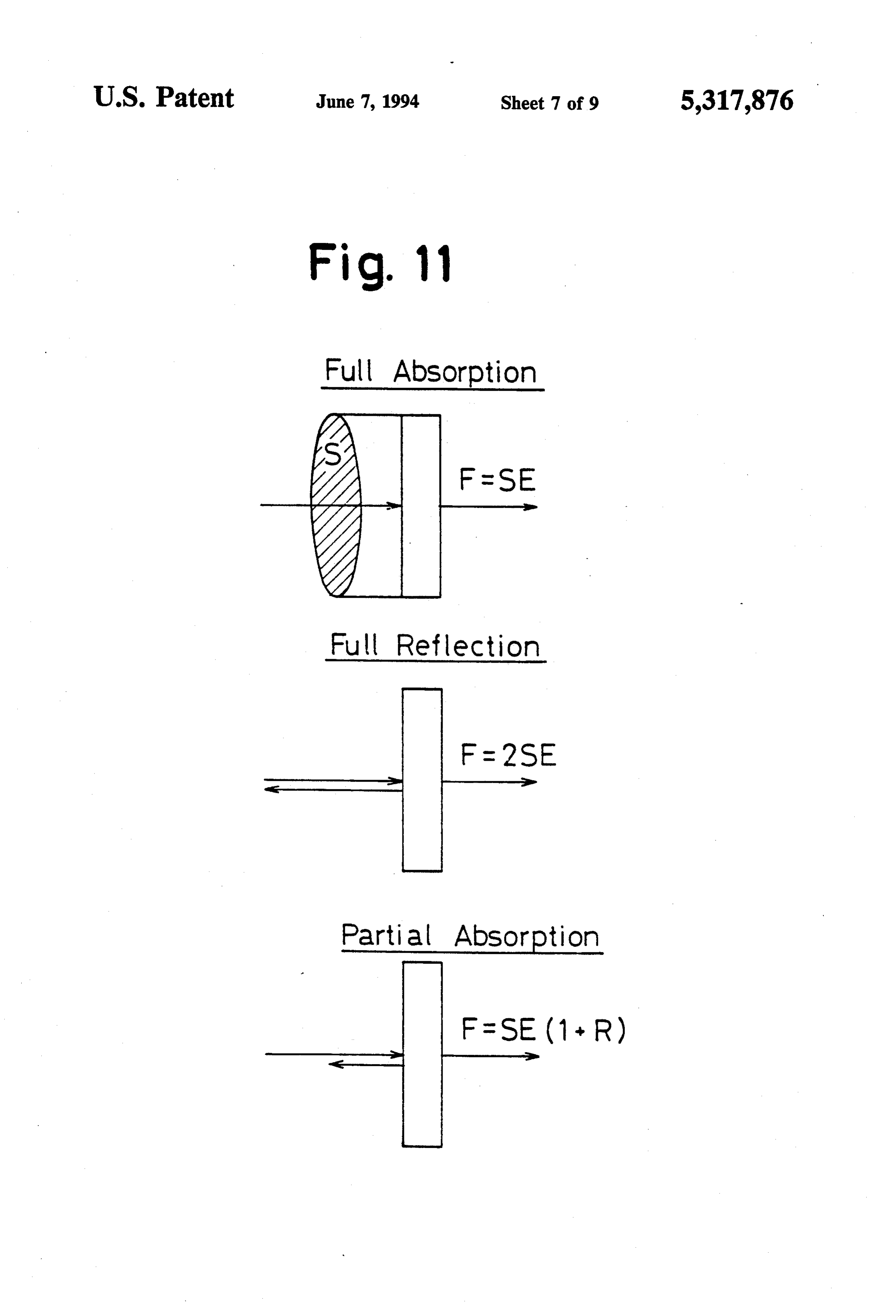
verter which can establish a rotational movement, a 10 FIG. 11 is view explaining the operation of the device linear movement or other movement. in FIG. 1;
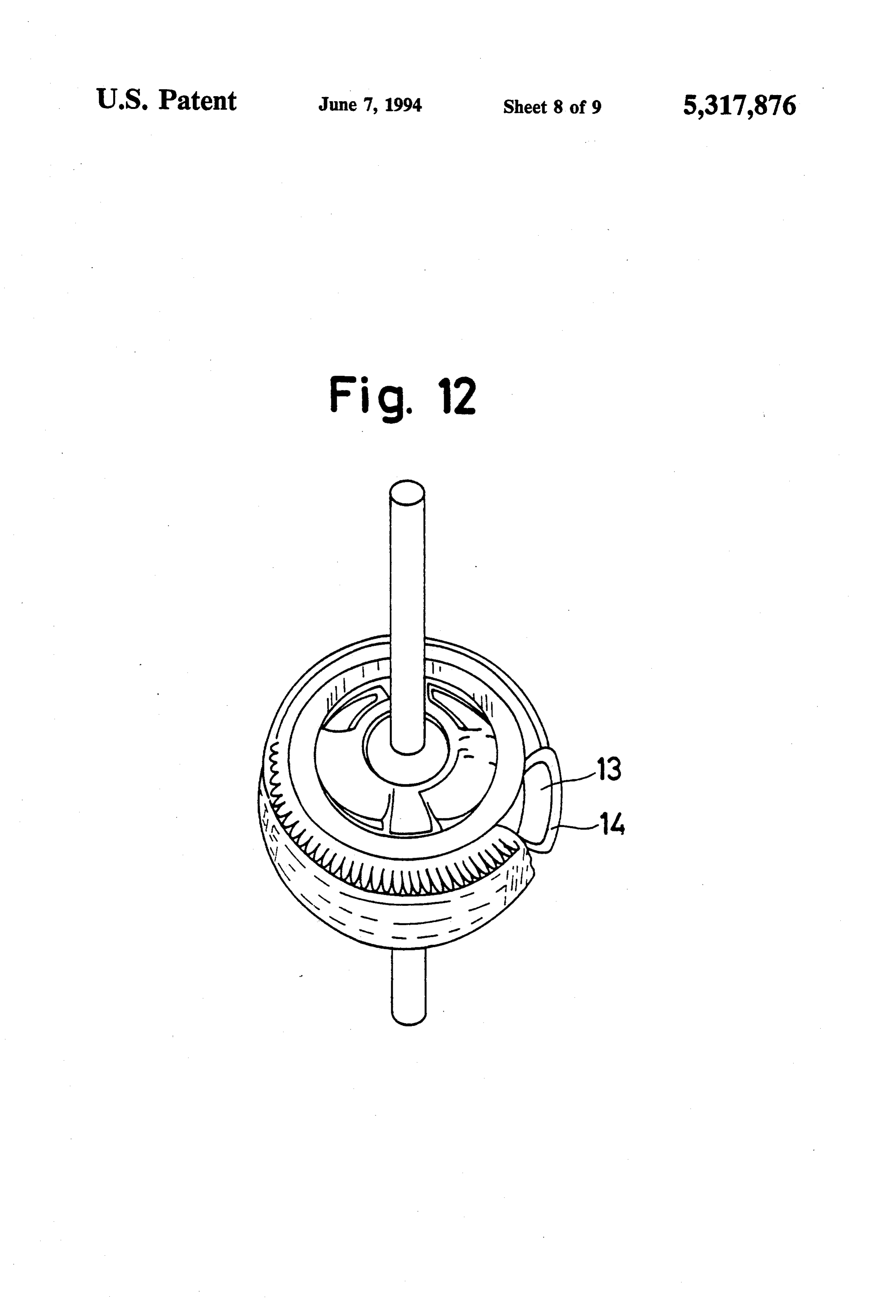
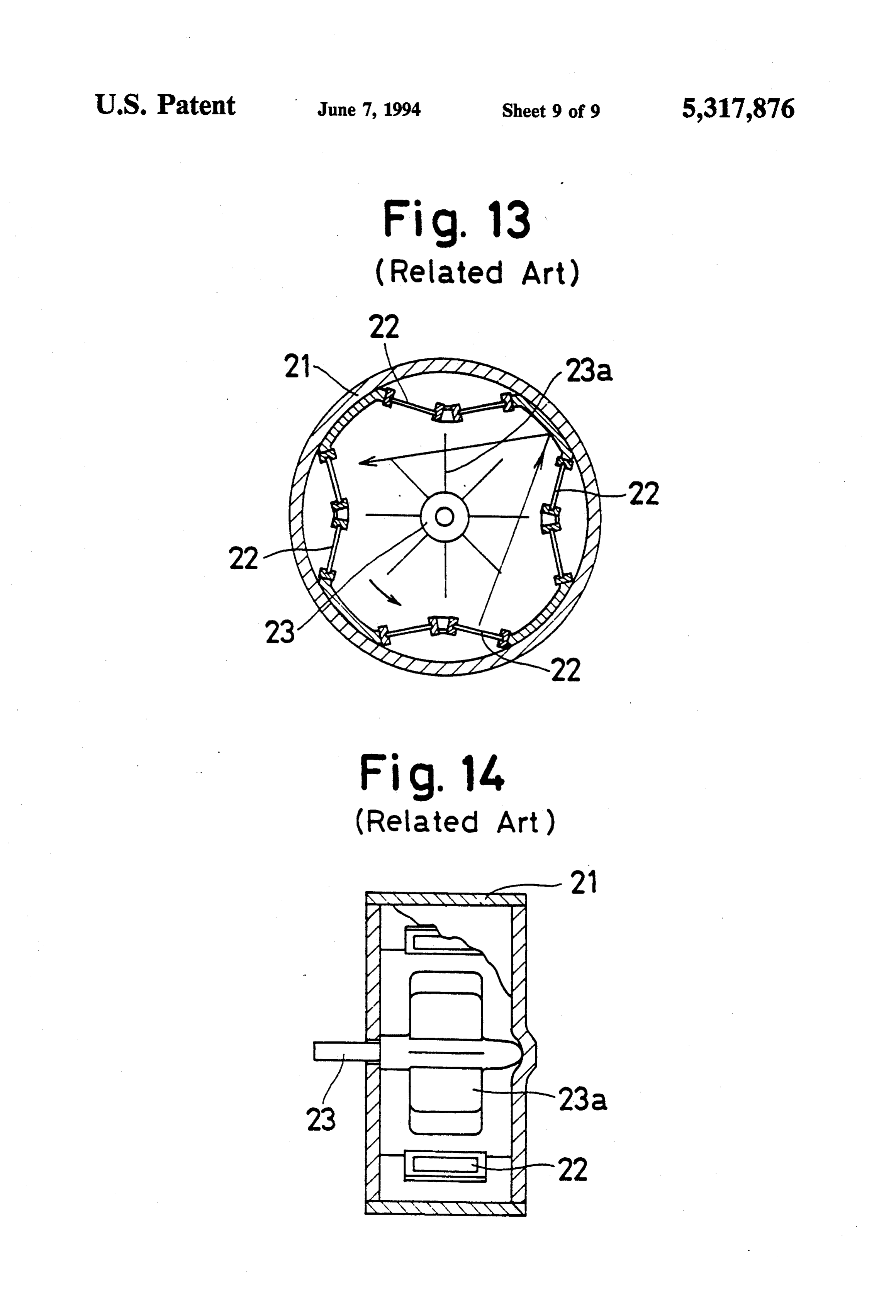
A conventional energy converter, which is pending according FIG. 12 is a perspective view of a rotor of a device in the United States Patent and Trademark Office under to a second embodiment of the present inven the Ser. No. of 07/917,964 (filing date: Jul. 24, 1992), is tion;
FIG. 13 is a plane view of a conventional energy shown in FIGS. 13 and 14. The conventional energy 5 converter; and converter includes a rotor 23 from which a plurality of FIG. 14 is a vertical cross-sectional view of the de equally pitched blades 23a are extended outwardly in vice in FIG. 13.
the radial direction, and a cylindrical housing 21 in which the rotor 23 and blades 23a are arranged. At an DESCRIPTION OF THE PREFERRED inner surface of the housing 21, there are secured a 20 EMBODIMENTS plurality of equally pitched resonators 22 so as to sur round the blades 23a. When each resonator 22 generates be described hereinunder inofdetail
Preferred embodiments the present invention will with reference to the a sound wave, the resulting radiation or sound pressure accompanying drawings.
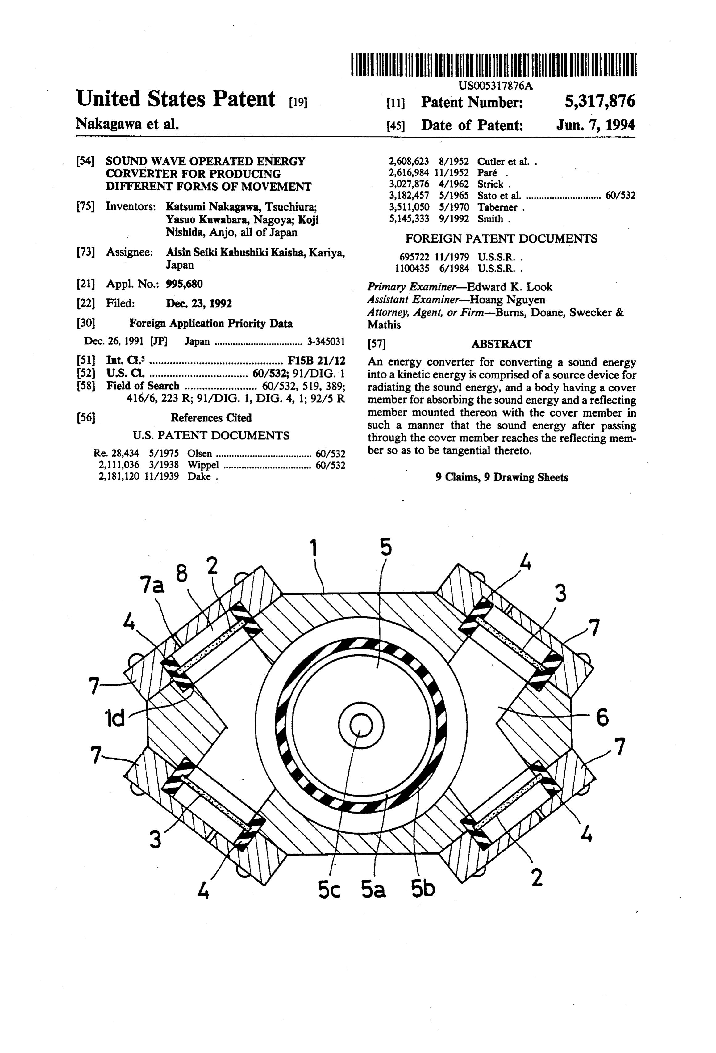
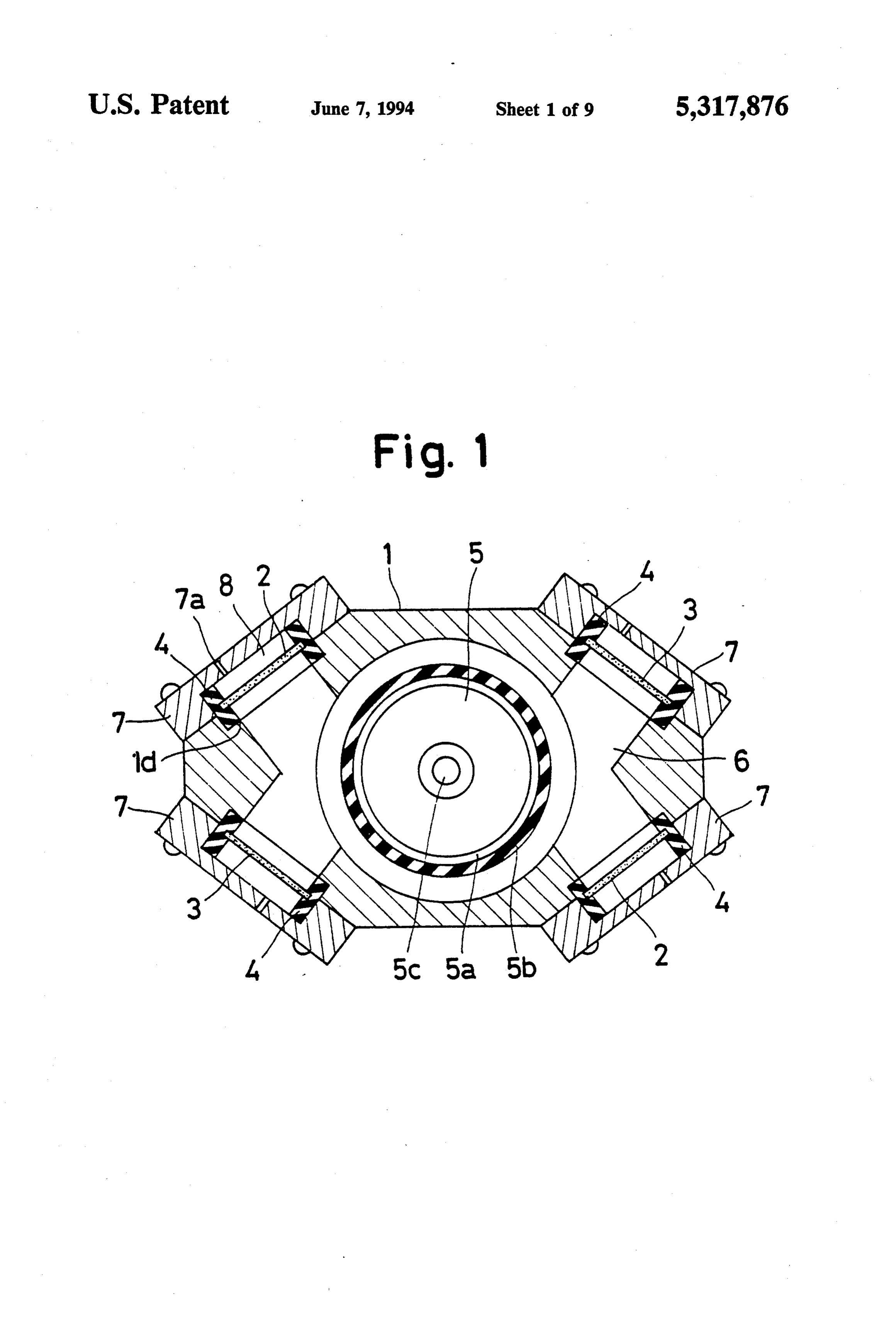
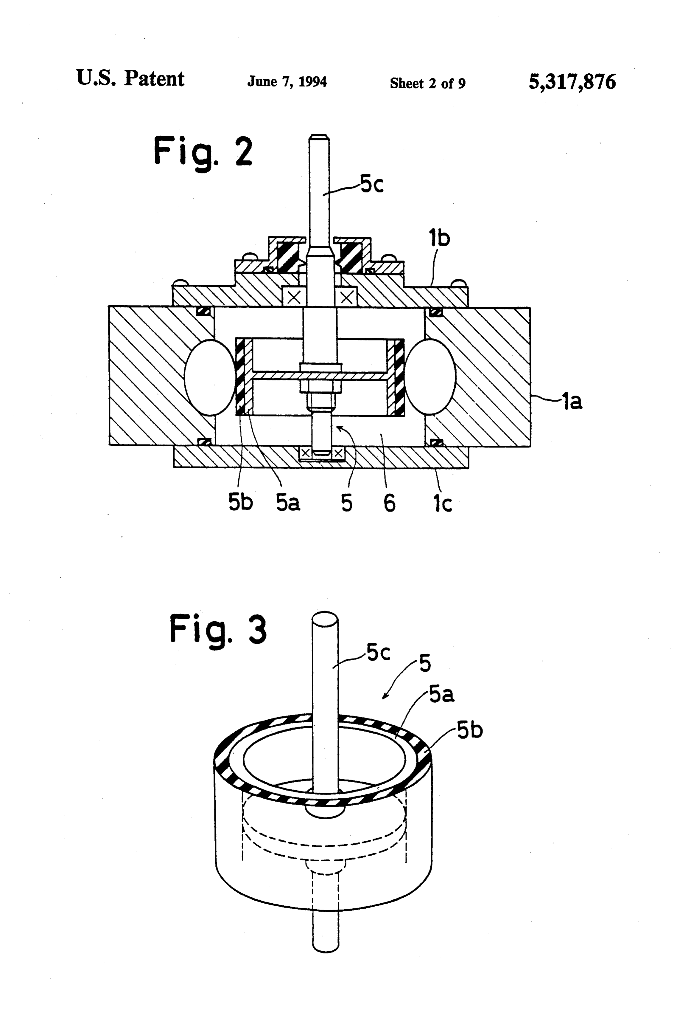
affects the blades 23a, which brings a rotation of the Referring first to FIGS. 1 and 3, an energy converter rotor 23. 25 which is in the form of a sound wave operated actuator In the foregoing structure, whenever the blade 23a is includes a housing 1 which has a main body 1a having substantially perpendicular to the direction along which an inner space, radiation pressure is transmitted the former can receive end of the inneran upper lid 1b closing an upper opened the energy of the latter efficiently. Is the blade 23a end of the inner space.andspace,
a lower lid 1c closing a lower plurality of windows 1d are makes an acute angle with respect to the foregoing 30 formed in the main body 1a. Within the inner space of direction after the foregoing rotation of the rotor 23a, the housing 1, an amount of fluid 6 as a medium is filled. the energy receipt at the blade 23a becomes less effi A rotor 5 is accommodated within the inner space of cient.
the housing 1 and is rotatably supported at each of the
SUMMARY OF THE INVENTION lids 1b and 1c. The rotor 5 includes a cylindrical body It is, therefore, a primary object of the present inven 5a, a shaft 5c on which the cylindrical body 5a is fixedly
tion to provide an energy converter without the forego rounds theand mounted, a cover member 5b which covers or sur entirety of the outer surface of the cylindri ing drawback.
In order to attain the foregoing object, an energy cal body 5a. The outer surface of the cylindrical body 5a serves for reflecting sound waves and the cover converter for converting a sound energy into a kinetic member 5b is set to absorb sound waves for the trans energy is comprised of a source device for radiating the mission thereof to the cylindrical body 5a, sound energy, and a body having a cover member for absorbing the sound energy and a reflecting member pairA of pair of diagonally spaced resonators 2 and another diagonally spaced resonators 3, each of which is mounted thereon with the cover member in such a supported at the corresponding window 1d in a fluid manner that the sound energy after passing through the 45 tight fashion by a rubber bush 4, are arranged in such a cover member reaches the reflecting member so as to be manner that two different resonators 2 and 3 are adja tangential thereto. cent each other. A plate 7 with an aperture 7a is secured BRIEF DESCRIPTION OF THE DRAWINGS to the main body 1a of the housing 1 so as to close the The above and other objects, features and advantages 50 chamber 8 iswindow respective 1d, which results in that an air of the present invention will be more apparent and more 6 via the resonators 2which defined is in opposition to the fluid readily appreciated from the following detailed descrip effectively propagate the soundair (3). The chamber 8 serves to wave when the resona tion of a preferred exemplarily embodiment of the pres tors 2 and 3 are turned on. If the actuator is desired to ent invention, taken in connection with the accompany be used within air, the rubber bush 4 as a sealing means ing drawings, in which; 55 is not required. On the other hand, when the actuator is FIG. 1 is a plane cross-sectional view of an energy desired to be used within a liquid, the rubber bush 4 is an converter according to a first embodiment according to essential element as a sealing means. The illustrated the present invention; embodiment shows the former case, and the air cham FIG. 2 is a vertical cross-sectional view of the device ber 8 is, via the aperture 7b, in fluid communication in FIG. 1; with atmosphere.
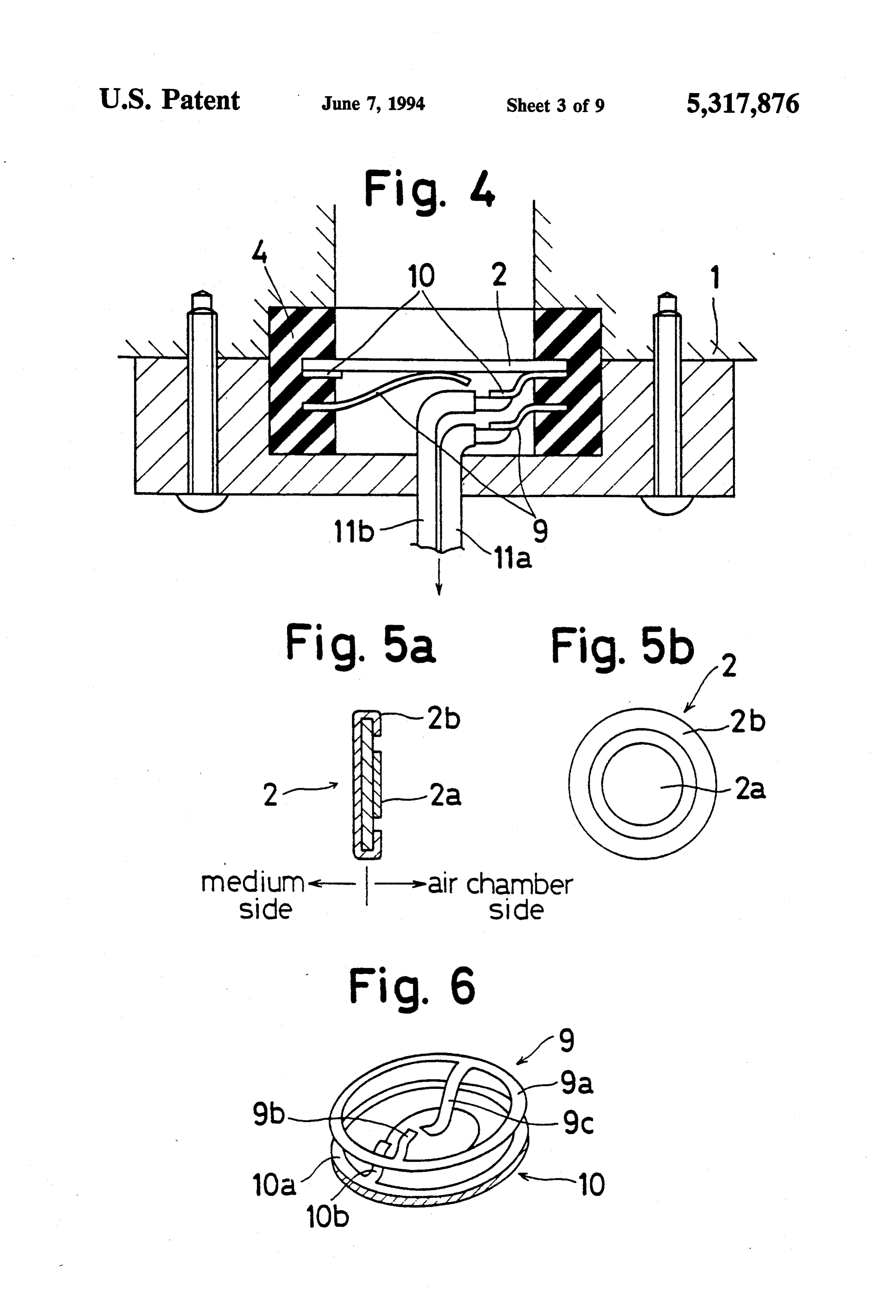
FIG. 3 is a perspective view of a rotor of the device If the actuator is set to used in liquid, by coinciding in FIG. 1 the same with the liquid 6, no effective seal between the FIG. 4 is a view showing a neighbourhood of a reso housing 1 and the shaft 5a is required.
nator of the device in FIG. 1 Each of the resonators 2 and 3 is adapted to emit or FIG. 5(A) is a side view of the resonator; 65 radiate, along its axial direction, the sound wave or FIG. 5(B) is a plane view of the resonator; sound beam so that the outermost portion thereof forms FIG. 6 is an exploded perspective view of the resona a tangent to the outer surface of the rotor 5. Each of the tor including positive and negative electrodes; resonators 2 and each of the resonators 3 serve for rotat
Page 12
ing the shaft 5 in the positive direction and the negative into water, however, it is only possible to input a sound direction, respectively. power of less than about 0.2 W/cm2 into atmosphere. In the present embodiment, a disk-shaped piezoelec Hence, liquids are suitable for the medium. However, it tric element is used for constituting each of the resona is not appropriate to employ a liquid, which absorbs or tors 2 and 3. The piezoelectric element is made of PZT damps the sound wave considerably, for the radiation (lead zirconate titanate), is of 1.2 mm in thickness, and is medium. In addition, when a liquid is disposed at one so rated with a longitudinal resonance frequency of 1.7 side of the resonator and a gas is disposed at the other MHz as to be used at an ultrasonic area. side of the resonator as is in the present embodiment, Referring to FIG. 4, there is illustrated a detailed almost all of the energy generated by the resonator can structure of a portion in the neighbourhood of the reso 10 be inputted into the liquid. In such a case, the electro nator 2. It is to be noted that similar structure can be acoustic efficiency reaches 90% or more. seen in the resonator 3. The disk-shaped resonator 2 is The force F, which a substance receives from a radia surrounded by a positive electrode 9, a negative elec tion pressure when the substance is in limitless plane trode 10, and the rubber bush 4. As shown in FIGS. progressive sound field whose sound energy density is 5(A) and 5(B), the resonator 2 has at its central portion 15 E, depends on the characteristics of the substance as and outer peripheral portion, respectively, a positive shown in FIG. 11. If the area of the outer surface of a electrode 2a and a negative electrode 2b. The negative resonator is defined to be S, in the case where the sub electrode 10 has, as shown in FIG. 6, an annular portion stance possesses full absorption characteristics, the for 10a and an inwardly extending terminal 10b. The annu mula of F=SE is established. In the case where the lar portion 10a is in contact with the negative electrode 20 substance possesses full reflection characteristics, the 2b of the resonator 2 (the resonator 3). The terminal 10b formula of F=2SE is established. If the substance pos of the negative electrode 10 is soldered with one end of sesses partial absorption characteristics, the formula of a wire 11b. The positive electrode 9 has an annular F=SE(1-R), where R is the reflective rate of the portion 9a and a pair of opposed inward extending sound intensity, is established. A rubber is the most terminals 9b and 9c. The annular portion 9a is located in 25 popular as the absorption substance. Most substances parallel with the resonator 2 (3) so as not to be in possess partial absorption characteristics. The reflective contact therewith. The terminal 9b of the positive elec rate R is related to the impedance of Z1 and Z2 of the trode 9 is soldered with one end of the wire 11a. The medium and substance, respectively which establishes terminal 9c formed in a spring mode is in contact with the formula of ((Z2-Z1)/(Z2--Z1))2. This rate be the positive electrode 2a of the resonator 2. The fre 30 comes about 90% (about 70%) with the combination of quency of the sound wave at the resonator 2 is adjust water and SUS or stainless steel (water and Al or al able by controlling the voltage and/or current in the minum).
wires 11a and 11b. In light of the fact that the resonator In the present embodiment, the sound wave is set to 2(3) is within the liquid 6, for the prevention of deterio be emitted or radiated obliquely to the cover member 5b ration of the resonator 2 (3), each of electrodes 2a, 2b, 35 as the absorption element and the resulting wave is 3a, 3b is in the form of a thin film which is obtained by reflected by the outer surface of the cylinder 5a. By the sputtering manner or CVD method. adjusting the raw material and thickness of the cover A sound field as shown in FIG. 9(A) is established at member 5b in such a manner that the sound wave may a side of the liquid 6 by the vibration of the resonator 2. be substantially damped during its travel in the cover The sound energy flux density of the sound field ex member 5b, a minimum reflected sound field can be tends along the axial direction of the resonator 2. established, which brings in that, as seen from FIG. 7, Though the actual acoustic radiation pressure is as com the cover member 5b receives only the radiation force plicated as the sound wave distribution, in the case of fl due to the incidence sound field near the outer sur the disk-shaped resonator having a diameter of 20 mm face of the cylinder body 5a. Thus, the foregoing struc within the liquid medium, the sound wave caused by the 45 ture enables the rotor 5 to receive at its outermost pe vibrations of the disk-shaped resonator generates the riphery the tangential component F" of the radiation sound field as illustrated in FIG. 9(B). When the fre force f1 due to the incidence sound field, resulting in quency of the vibration of the disk-shaped resonator is that the maximum torque can be obtained. Without approximately 1 MHz or more, the sound field exhibits absorption element 5b, due to cancellation of both radia a half value angle of about 2 through 3 degrees or less, 50 tion forces in opposite directions, the rotor 5 remains and is formed like a beam. Thus, the sound field can be fixed.
approximated to a plane progressive wave in practical The cover member 5b is set to receive a force for use. On the other hand, when the frequency of the rotating the rotor in the counter-clockwise direction by vibration of the resonator is high, there arises the damp absorbing an energy from the resonator. The cover ing or less. Thus, when the frequency of the vibration of 55 member 5b receives the force fl upon incidence of the the resonator is not less than 10 MHz, the damping sound wave and the force f2 upon reflection thereof. distance is several tens of centimeters or less in liquid as The component of the forces fl and f2 is applied to the shown in FIG. 10, which results in that it is preferable rotor 5 in the tangential direction thereof, and results in to operate or vibrate the resonator at a frequency rang a large rotating force or torque. It is to be noted that as ing from 1 through 10 MHz in order to constitute an seen in FIG. 8 the cylinder body 5a receives the force f3 energy converter of a few centimeters through several upon incidence of the sound wave and the force f4 upon tens of centimeters in size or scale. reflection thereof.
Moreover, when a liquid is the radiation medium for The transmission coefficient of the sound intensity in the sound wave, it is possible to input a sound power the cover member 5b, which is the reciprocal of the which is larger by three digits than the case where a gas 65 reflection coefficient thereof, is represented in the for is the radiation medium for the sound wave. For in mula of Ts 1-R=4Z1Z2/ (Z1--Z2)2. stance, in the case where the PZT is used as the resona The sound impedance in water equals that in rubber, tor, it is possible to input a sound power of 800 W/cm2 which leads to R=0 and T=100%. In the light of the
Page 13
fact that the sound wave absorption and ability of rub source means for radiating an acoustic radiation pres ber is high, the rubber is the most suitable for the cover sure; and 5b. In addition, the reflection coefficient of sound inten a body having a cover member and a reflecting mem sity is about 90% with the combination of water and ber which are arranged in layers, the body receiv stainless steel like the combination of water and SUS, ing the acoustic radiation pressure such that the which reveals that stainless steel is excellent as a raw acoustic radiation pressure passes through the material of the cylinder 5a. cover member and is transmitted to the reflecting In order to obtain 100% in reflection coefficient, a member along a tangential direction thereof. gas is available instead of the metal reflecting member. 10 the2.source
An energy converter as recited in claim 1, wherein
FIG. 12 shows another embodiment in which the sound in opposingmeans includes a pair of resonators mounted relation with respect to the body.
wave is set to be reflected at the border portion betwee 3. An energy converter as recited in claim 1, wherein a rubber layer 14 and an air layer 13. the source means includes a first pair of resonators For obtaining the maximum torque, half of the en mounted in opposing relation with respect to the body ergy of the sound wave is to be absorbed at its first 15 for moving the body in one direction and another pair incidence in the cover 5b and the remaining half of the of resonators mounted in opposing relation with respect energy is to be absorbed after its reflection. By adjusting to the body for moving the body in an opposite direc any of the frequency of the resonator, the distance be tion.
tween the resonator and the cover, rating of the cover 4. An energy converter as recited in claim 1, wherein 5b, the sound wave energy can be converted into a 20 a vibration frequency of the source means is not less rotational movement or other movement in efficiency. than 1 MHz.
As mentioned above, no friction is generated during 5. An energy converter as recited in claim 1, wherein energy conversion as seen in the conventional manner, a vibration frequency of the source means is 10 MHz or which results in the establishment of an efficient energy less.
conversion. The present invention enables the energy 25 6. An energy converter as recited in claim 1, wherein converter to be used in a liquid and such usage increases a vibration frequency of the source means ranges from the cooling effect of the converter. Furthermore, pres 1 MHz through 10 MHz.
sure can be derived from the sound wave at its inci 7. An energy converter as recited in claim 1, wherein dence and reflection, which enables flexibility in design 30 the source means includes a pair of electrodes each of such as a location of the rotor. which is obtained by CVD method. It should be apparent to one skilled in the art that the 8. An energy converter as recited in claim 1, wherein above-described embodiments are merely illustrative of the source means includes a pair of electrodes each of which is obtained by sputtering manner.
but a few of the many possible specific embodiments of 9. An energy converter as recited in claim 1, wherein the present invention. Numerous and various other 35 said source arrangements can be readily devised by those skilled in tors, one of meanssaid comprises two spaced apart resona resonators radiating an acoustic radia the art without departing from the spirit and scope of tion pressure to cause the body to move in one direction the invention as defined in the following claims. and the other resonator radiating an acoustic radiation What is claimed is: pressure to cause the body to move in an opposite direc 1. An energy converter for converting sound energy 40 tion.
into kinetic energy comprising: k k 8 k
Provenance
- Collection
- Cited prior art
- Original PDF
- patentimages.storage.googleapis.com →
- Filed
- 1992-12-23
- Pages
- 13
- Method
- pdftotext (the PDF's own text layer) + pdftoppm 300dpi page scans
- Source
- Google Patents bibliographic record
- Granted
- 1994-06-07
- Inventors
- Katsumi Nakagawa; Yasuo Kuwabara; Koji Nishida; Aisin Seiki Co Ltd
- Transcribed from
- patentimages.storage.googleapis.com →